EP0173671A2 - Device for covering openings of tiled walls - Google Patents
Device for covering openings of tiled walls Download PDFInfo
- Publication number
- EP0173671A2 EP0173671A2 EP85890170A EP85890170A EP0173671A2 EP 0173671 A2 EP0173671 A2 EP 0173671A2 EP 85890170 A EP85890170 A EP 85890170A EP 85890170 A EP85890170 A EP 85890170A EP 0173671 A2 EP0173671 A2 EP 0173671A2
- Authority
- EP
- European Patent Office
- Prior art keywords
- socket
- cover
- support tabs
- recess
- hinge fittings
- Prior art date
- Legal status (The legal status is an assumption and is not a legal conclusion. Google has not performed a legal analysis and makes no representation as to the accuracy of the status listed.)
- Granted
Links
- 210000002105 tongue Anatomy 0.000 claims abstract description 6
- 238000004873 anchoring Methods 0.000 claims abstract description 3
- 238000009434 installation Methods 0.000 description 2
- 230000007812 deficiency Effects 0.000 description 1
- 238000010586 diagram Methods 0.000 description 1
- 230000005294 ferromagnetic effect Effects 0.000 description 1
- 230000005291 magnetic effect Effects 0.000 description 1
- 239000004570 mortar (masonry) Substances 0.000 description 1
Images
Classifications
-
- E—FIXED CONSTRUCTIONS
- E04—BUILDING
- E04F—FINISHING WORK ON BUILDINGS, e.g. STAIRS, FLOORS
- E04F19/00—Other details of constructional parts for finishing work on buildings
- E04F19/08—Built-in cupboards; Masks of niches; Covers of holes enabling access to installations
- E04F19/086—Covers with magnetic fixing means
-
- A—HUMAN NECESSITIES
- A47—FURNITURE; DOMESTIC ARTICLES OR APPLIANCES; COFFEE MILLS; SPICE MILLS; SUCTION CLEANERS IN GENERAL
- A47K—SANITARY EQUIPMENT NOT OTHERWISE PROVIDED FOR; TOILET ACCESSORIES
- A47K3/00—Baths; Douches; Appurtenances therefor
- A47K3/16—Devices for fastening baths to floors or walls; Adjustable bath feet ; Lining panels or attachments therefor
- A47K3/161—Bathtub aprons
Definitions
- the invention relates to a covering device for cut-out tiled walls, with a mount that can be inserted into the cut-out and that receives a tile cover articulated via a pivot bearing, the pivot bearing engaging support tabs or the like directed normal to the closing plane.
- the lids are usually held detachably in the sockets by means of screw connections, magnetic locks or the like, the lids being able to be combined with a wide variety of sockets, be they fixed or adjustable frames or individually displaceable sections.
- handling these lids is quite cumbersome, since they have to be gripped with both hands to open the recess, removed and then put away loosely and, when closing, require careful installation in the socket.
- sockets can only be embedded in the recess or between masonry and tiles with comparatively little strength without complex masonry work and offer this Cover thus too weak a support for a pivot bearing, which is further compounded by the fact that these sockets, in order to be as little visible from the outside as possible, consist of thin sheets or profiles and do not even withstand any major loads.
- the invention is therefore based on the object of avoiding these deficiencies and of creating a covering device of the type described at the outset which is distinguished by a particularly simple cover holder which can be used anywhere and, above all, can be combined with any frames.
- hinge fittings serve as pivot bearings, which are arranged in the corner regions of the socket, and in that the support tabs carrying the hinge fittings are punched out holding tongues or the like for anchoring have in the recess reveal.
- the tile covers which in the case of larger formats consist of a base plate with correspondingly glued tiles, are mounted in the area of the edge on the hinge fittings and can therefore be swiveled around the edge in question, so that the cover does not penetrate the opening when opening and does not cause any space problems can.
- the hinge fittings only need to be attached to the support tabs in such a deep position that the cover surface may be aligned with the wall tiles, taking into account the thickness of the base plate, and the desired optically perfect and conveniently handled cover is ready.
- the support tabs which are well supported in the corner areas and anchored directly in the recess reveal, can easily absorb the main part of the hinge-related loads and pass them on directly to the adjacent masonry, so that there is practically no additional load for the frame and every overuse is also thinner, even in the recess only a little firmly used sockets is avoided. Since the holding tongues of the support tabs or the like without difficulty at the same time as the setting of the frame in a mortar layer. can be embedded, the assembly effort remains low and comparable to that for conventional sockets.
- the support tabs are also angled according to the corner of the recess, the rigidity and strength of the support increase and it is even possible to use the To reduce the frame to individual loose elbows, so that this covering device can be used particularly efficiently regardless of the size of the cover or the recess.
- a tile cover 3 which consists of four glued to a base plate 4 that resemble the wall tiles 1 a Tile 3 a exists.
- this cover 3 there are four individual angle pieces 5a, 5b, each of which sits in corners of the recess 2 and is fixed by fastening tongues 6 which can be inserted between the wall tiles 1a and under the tiles.
- the angle pieces 5a for receiving the cover 3 carry hinge fittings 7, the angle pieces 5a being equipped with support tabs 8 for fastening these fittings 7, which follow the angular shape in their course.
- These support tabs 8 have punched-out retaining tongues 9, with which they can be anchored in the reveal 2a of the recess 2 and thereby easily absorb the stresses caused by the hinges.
- These Hinges 7 are fastened to the support tab 8 with the stop plate 10a assigned to the socket and fixed to the base plate 3a with the stop plate 10b assigned to the tile cover 3.
- the two stop plates 10a, 10b are perpendicular to one another in the closed position, and when the hinge is opened, the stop plate 10b is first raised opposite the stop plate 10a and then swung open, for which purpose the stop plates 10a, 10b are connected to one another in a manner indicated by scissor-like links 10c.
- the angle pieces 5b opposite the angle pieces 5b carry instead of the hinge fittings 7 permanent magnets 11 which cooperate with the ferromagnetic base plate 4 of the cover 3 and hold it in the closed position.
- the result is a cover device that can be easily adapted and set to various recess sizes and whose lid can also be handled comfortably and always sits exactly in the socket.
Landscapes
- Engineering & Computer Science (AREA)
- Architecture (AREA)
- Health & Medical Sciences (AREA)
- Public Health (AREA)
- Epidemiology (AREA)
- General Health & Medical Sciences (AREA)
- Civil Engineering (AREA)
- Structural Engineering (AREA)
- Finishing Walls (AREA)
Abstract
Eine Abdeckvorrichtung für Aussparungen verfliester Wände besteht aus einer in die Aussparung einsetzbaren Fassung, die einen über Schwenklager angelenkten Fliesendeckel aufnimmt. Die Schwenklager greifen an normal zur Schliessebene des Fliesendeckels gerichteten Stützlappen der Fassung an.A covering device for cut-out tiled walls consists of a socket which can be inserted into the cut-out and which receives a tile cover articulated via swivel bearings. The swivel bearings engage on the support tabs of the socket that are normal to the closing level of the tile cover.
Um eine besonders einfache, mit beliebigen Fassungen kombinierbare Deckelhalterung zu erreichen, dienen Scharnierbeschläge (7) als Schwenklager, die in den Eckbereichen der Fassung angeordnet sind. Die die Scharnierbeschläge (7) tragenden Stützlappen (8) weisen ausgestanzte Haltezungen (9) zur Verankerung in der Aussparungslaibung auf.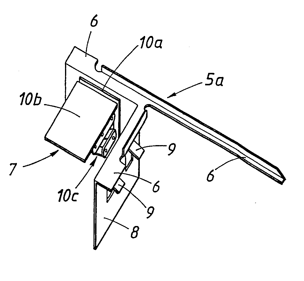
Description
Die Erfindung betrifft eine Abdeckvorrichtung für Aussparungen verfliester Wände, mit einer in die Aussparung einsetzbaren Fassung, die einen über Schwenklager angelenkten Fliesendeckel aufnimmt, wobei die Schwenklager an normal zur Schließebene gerichteten Stützlappen od. dgl. der Fassung angreifen.The invention relates to a covering device for cut-out tiled walls, with a mount that can be inserted into the cut-out and that receives a tile cover articulated via a pivot bearing, the pivot bearing engaging support tabs or the like directed normal to the closing plane.
Um die Zugänglichkeit zu den in den Aussparungen vorhandenen Einrichtungen und Armaturen od.dgl. zu wahren, werden die Deckel meistens durch Verschraubungen, Magnetverschlüsse od. dgl. abnehmbar in den Fassungen gehalten, wobei die Deckel mit den verschiedensten Fassungen, seien es feste oder verstellbare Rahmen oder einzeln zu versetzende Teilstücke, kombiniert werden können. Allerdings ist das Hantieren dieser Deckel recht umständlich, da sie zum Öffnen der Aussparung beidhändig erfaßt, abgenommen und dann lose weggelegt werden müssen und beim Schließen wiederum ein sorgfältiges Einrichten in die Fassung verlangen. Bequemere Schwenkdeckel haben sich bisher nicht durchgesetzt, denn die üblichen Fassungen können ohne aufwendige Mauerungsarbeiten nur mit vergleichsweise geringer Festigkeit in die Aussparung bzw. zwischen Mauerwerk und Fliesen eingebettet werden und bieten dem Deckel somit für eine Schwenklagerung eine zu schwache Abstützung, wozu noch kommt, daß diese Fassungen, um von außen möglichst wenig sichtbar zu sein, aus dünnen Blechen oder Profilen bestehen und selbst auch keiner größeren Belastung standhalten.To the accessibility to the existing facilities and fittings or the like in the recesses. To maintain, the lids are usually held detachably in the sockets by means of screw connections, magnetic locks or the like, the lids being able to be combined with a wide variety of sockets, be they fixed or adjustable frames or individually displaceable sections. However, handling these lids is quite cumbersome, since they have to be gripped with both hands to open the recess, removed and then put away loosely and, when closing, require careful installation in the socket. So far, more convenient swivel covers have not prevailed, because the usual sockets can only be embedded in the recess or between masonry and tiles with comparatively little strength without complex masonry work and offer this Cover thus too weak a support for a pivot bearing, which is further compounded by the fact that these sockets, in order to be as little visible from the outside as possible, consist of thin sheets or profiles and do not even withstand any major loads.
Wie die FR-PS 2 505 921 zeigt, gibt es zwar schon Abdeckvorrichtungen mit schwenkbarem Deckel, doch ist diesem Deckel eben ein stabiler Rahmen als Fassung zugeordnet, der umlaufende Stützlappen mit zusätzlichen, das Mauerwerk hintergreifenden Befestigungsflanschen aufweist. Einander gegenüberliegende, mittig am Rahmen sitzende Lagerzapfen, die in entsprechende Lageraugen des Deckels eingreifen, bilden das Schwenklager für den Deckel, der so um eine mittlere Querachse verschwenkbar ist. Diese Abdeckvorrichtung verlangt daher, abgesehen vom teuren Rahmen, umständliche Vorbereitungs- und Versetzungsarbeiten, erfordert zudem genügend große, Platz zum Aufschwenken des Deckels bietende Aussparungen und stört das Bild einer einheitlichen Wandverfliesung merkbar, so daß sie trotz des Aufwandes nur beschränkt eingesetzt werden kann.As the FR-
Der Erfindung liegt daher die Aufgabe zugrunde, diese Mängel zu vermeiden und eine Abdeckvorrichtung der eingangs geschilderten Art zu schaffen, die sich durch eine besonders einfache, überall anwendbare und vor allem auch mit beliebigen Fassungen kombinierbare Deckelhalterung auszeichnet.The invention is therefore based on the object of avoiding these deficiencies and of creating a covering device of the type described at the outset which is distinguished by a particularly simple cover holder which can be used anywhere and, above all, can be combined with any frames.
Die Erfindung löst diese Aufgabe dadurch, daß Scharnierbeschläge als Schwenklager dienen, die in den Eckbereichen der Fassung angeordnet sind, und daß die die Scharnierbeschläge tragenden Stützlappen ausgestanzte Haltezungen od, dgl. zur Verankerung in der Aussparungslaibung aufweisen. Die Fliesendeckel, die bei größeren Formaten aus einer Grundplatte mit entsprechend aufgeklebten Fliesen bestehen, werden im Bereich des Randes an den Scharnierbeschlägen montiert und lassen sich demnach etwa um die betreffende Randkante schwenken, wodurch der Deckel beim Öffnen nicht in die Aussparung eindringt und keine Platzprobleme hervorrufen kann. Die Scharnierbeschläge brauchen an den Stützlappen lediglich in einer so tiefen Lage befestigt zu werden, daß die Deckeloberfläche gegebenenfalls unter Berücksichtigung der Grundplattenstärke mit den Wandfliesen fluchtet, und die gewünschte optisch einwandfreie und dazu noch bequem hantierbare Abdeckung ist fertig. Dabei können die in den Eckbereichen gut abgestützten und direkt in der Aussparungslaibung verankerten Stützlappen den Hauptteil der scharnierbedingten Belastungen problemlos aufnehmen und unmittelbar an das anliegende Mauerwerk weitergeben, so daß es für die Fassung praktisch keine Mehrbelastung gibt und jede Überbeanspruchung auch dünner, selbst in der Aussparung nur wenig fest eingesetzten Fassungen vermieden ist. Da die Haltezungen der Stützlappen ohne Schwierigkeit gleichzeitig mit dem Setzen der Fassung in eine Mörtelschicht od.dgl. eingebettet werden können, bleibt der Montageaufwand gering und mit dem für übliche Fassungen vergleichbar. Sind die Stützlappen außerdem dem Eckverlauf der Aussparung entsprechend abgewinkelt, erhöhen sich Steifigkeit und Festigkeit der Abstützung und es ist sogar möglich, die Fassung auf einzelne lose Winkelstücke zu reduzieren, so daß sich diese Abdeckvorrichtung unabhängig von der Größe des Deckels bzw. der Aussparung besonders rationell einsetzen läßt.The invention solves this problem in that hinge fittings serve as pivot bearings, which are arranged in the corner regions of the socket, and in that the support tabs carrying the hinge fittings are punched out holding tongues or the like for anchoring have in the recess reveal. The tile covers, which in the case of larger formats consist of a base plate with correspondingly glued tiles, are mounted in the area of the edge on the hinge fittings and can therefore be swiveled around the edge in question, so that the cover does not penetrate the opening when opening and does not cause any space problems can. The hinge fittings only need to be attached to the support tabs in such a deep position that the cover surface may be aligned with the wall tiles, taking into account the thickness of the base plate, and the desired optically perfect and conveniently handled cover is ready. The support tabs, which are well supported in the corner areas and anchored directly in the recess reveal, can easily absorb the main part of the hinge-related loads and pass them on directly to the adjacent masonry, so that there is practically no additional load for the frame and every overuse is also thinner, even in the recess only a little firmly used sockets is avoided. Since the holding tongues of the support tabs or the like without difficulty at the same time as the setting of the frame in a mortar layer. can be embedded, the assembly effort remains low and comparable to that for conventional sockets. If the support tabs are also angled according to the corner of the recess, the rigidity and strength of the support increase and it is even possible to use the To reduce the frame to individual loose elbows, so that this covering device can be used particularly efficiently regardless of the size of the cover or the recess.
In der Zeichnung ist der Erfindungsgegenstand rein schematisch dargestellt, und zwar zeigen
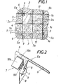
- Fig. 1 eine erfindungsgemäße Abdeckvorrichtung in Draufsicht und
- Fig. 2 einen Teil der Fassung dieser Abdeckvorrichtung größeren Maßstabes im Schaubild.
- Fig. 1 shows a cover device according to the invention in plan view and
- Fig. 2 shows a part of the version of this cover device on a larger scale in the diagram.
Um in einer verfliesten Wand 1 eine Aussparung'2 mit nicht weiter dargestellten Armaturen, Installationseinrichtungen od. dgl. ohne merkbare Unterbrechung der Wandverfliesung abdecken zu können, ist ein Fliesendeckel 3 vorgesehen, der aus vier auf einer Grundplatte 4 aufgeklebten, den Wandfliesen 1 a gleichenden Fliesen 3 a besteht. Zur Aufnahme dieses Deckels 3 gibt es als Fassung vier einzelne Winkelstücke 5a, 5b, die jeweils in Ecken der Aussparung 2 sitzen und durch zwischen die Wandfliesen 1a und unter die Fliesen einschiebbare Befestigungszungen 6 fixiert sind. Damit der Fliesendeckel 3 bequem gehandhabt werden kann, tragen die Winkelstücke 5a zur Aufnahme des Deckels 3 Scharnierbeschläge 7, wobei zur Befestigung dieser Beschläge 7 die Winkelstücke 5a mit Stützlappen 8 ausgestattet sind, die in ihrem Verlauf der Winkelform folgen. Diese Stützlappen 8 weisen ausgestanzte Haltezungen 9 auf, mit denen sie in der Laibung 2a der Aussparung 2 verankert werden können und dadurch die durch die Scharniere auftretenden Belastungen schwierigkeitslos aufnehmen. Diese Scharniere 7 sind mit der der Fassung zugeordneten Anschlagplatte 10a am Stützlappen 8 befestigt und mit der dem Fliesendeckel 3 zugeordneten Anschlagplatte 10b an der Grundplatte 3a fixiert. Die beiden Anschlagplatten 10a, 10b stehen in Schließstellung aufeinander senkrecht, und beim Öffnen des Scharnieres wird die Anschlagplatte 10b der Anschlagplatte 10a gegenüber zuerst angehoben und dann aufgeschwenkt, wozu die Anschlagplatten 10a, 10b in angedeuteter Weise über scherenartig zusammenwirkende Lenker 10c miteinander verbunden sind.In order to be able to cover a cut-out 2 in a
Die den Winkelstücken 5a gegenüberliegenden Winkelstücke 5b tragen statt der Scharnierbeschläge 7 Permanentmagnete 11, die mit der ferromagnetischen Grundplatte 4 des Deckels 3 zusammenwirken und diesen in Schließstellung festhalten. Es entsteht eine Abdeckvorrichtung, die sich problemlos an verschiedenste Aussparungsgrößen anpassen und setzen läßt und deren Deckel noch dazu bequem gehandhabt werden kann und stets exakt in der Fassung sitzt.The
Claims (1)
Applications Claiming Priority (2)
| Application Number | Priority Date | Filing Date | Title |
|---|---|---|---|
| AT2741/84 | 1984-08-28 | ||
| AT0274184A AT380054B (en) | 1984-08-28 | 1984-08-28 | COVER DEVICE FOR RECESSING TILED WALLS |
Publications (3)
| Publication Number | Publication Date |
|---|---|
| EP0173671A2 true EP0173671A2 (en) | 1986-03-05 |
| EP0173671A3 EP0173671A3 (en) | 1986-12-17 |
| EP0173671B1 EP0173671B1 (en) | 1988-11-23 |
Family
ID=3539560
Family Applications (1)
| Application Number | Title | Priority Date | Filing Date |
|---|---|---|---|
| EP85890170A Expired EP0173671B1 (en) | 1984-08-28 | 1985-07-31 | Device for covering openings of tiled walls |
Country Status (5)
| Country | Link |
|---|---|
| US (1) | US4586626A (en) |
| EP (1) | EP0173671B1 (en) |
| AT (1) | AT380054B (en) |
| CA (1) | CA1243466A (en) |
| DE (1) | DE3566426D1 (en) |
Families Citing this family (2)
| Publication number | Priority date | Publication date | Assignee | Title |
|---|---|---|---|---|
| FR2807640B1 (en) * | 2000-04-17 | 2004-03-12 | Nicoll Raccords Plastiques | VISIT DOOR FOR BUILT-IN BATHTUB OR THE LIKE |
| CN111583254B (en) * | 2020-05-18 | 2023-04-14 | 湘潭大学 | A visual inspection method for abnormal placement direction and order of crankshaft cover group |
Family Cites Families (7)
| Publication number | Priority date | Publication date | Assignee | Title |
|---|---|---|---|---|
| US3199713A (en) * | 1961-11-10 | 1965-08-10 | Walker Brothers | Adapter for access units of underfloor ducts |
| US3187922A (en) * | 1962-05-18 | 1965-06-08 | Raceways Inc | Flush pans |
| FR1392511A (en) * | 1963-11-14 | 1965-03-19 | Removable hatch to visit installations or devices under bathtubs or other built-in elements | |
| FR2056071A6 (en) * | 1969-08-28 | 1971-05-14 | Tavoschi Fulvio | |
| FR2505921B1 (en) * | 1981-05-15 | 1985-10-31 | Durand Jean | UNIVERSAL VISIT DOOR FOR TILED INSTALLATIONS |
| DE3121854A1 (en) * | 1981-06-02 | 1982-12-30 | Wilhelm 7129 Ilsfeld Wirth | Wickets for garages |
| DE3302042A1 (en) * | 1983-01-22 | 1984-07-26 | Karl-Heinz Wien Sperling | Detachable covering for an opening in a tiled wall (tiled door) |
-
1984
- 1984-08-28 AT AT0274184A patent/AT380054B/en not_active IP Right Cessation
-
1985
- 1985-07-31 EP EP85890170A patent/EP0173671B1/en not_active Expired
- 1985-07-31 DE DE8585890170T patent/DE3566426D1/en not_active Expired
- 1985-08-07 CA CA000488207A patent/CA1243466A/en not_active Expired
- 1985-08-12 US US06/764,537 patent/US4586626A/en not_active Expired - Fee Related
Also Published As
| Publication number | Publication date |
|---|---|
| AT380054B (en) | 1986-04-10 |
| US4586626A (en) | 1986-05-06 |
| EP0173671B1 (en) | 1988-11-23 |
| DE3566426D1 (en) | 1988-12-29 |
| CA1243466A (en) | 1988-10-25 |
| EP0173671A3 (en) | 1986-12-17 |
| ATA274184A (en) | 1985-08-15 |
Similar Documents
| Publication | Publication Date | Title |
|---|---|---|
| DE60023448T2 (en) | SHOWER ARRANGEMENT | |
| DE2916002A1 (en) | SIDE FRAME FOR OFFICE FURNITURE | |
| EP0173671B1 (en) | Device for covering openings of tiled walls | |
| DE69406117T2 (en) | FLOOR DOOR CLOSER | |
| DE2847007C2 (en) | False ceiling | |
| Miller et al. | Information and training needs of agricultural faculty related to distance education | |
| DE8130060U1 (en) | Device for holding shower fittings | |
| US3973616A (en) | Alignment device for bi-fold doors | |
| DE102005001624A1 (en) | Combinable plug-in frame | |
| DE69512383T2 (en) | STORAGE SYSTEM FOR COMPACT PANELS | |
| DE1465775A1 (en) | switch cabinet | |
| DE10007431A1 (en) | Partitioning office space to create discrete and separate office units | |
| DE3933940C2 (en) | ||
| EP0602334B1 (en) | Suspended ceiling assembly | |
| DE8028235U1 (en) | HINGE FOR WINDOWS AND DOORS | |
| DE3410079A1 (en) | Securing means for a detachable covering of an opening in a tiled wall | |
| EP0498789B1 (en) | Covering device for angular openings in tiled walls | |
| DE3302042A1 (en) | Detachable covering for an opening in a tiled wall (tiled door) | |
| DE8503779U1 (en) | REVISION TURN FOR TILED PANELING | |
| DE2607425C2 (en) | Device for attaching a box-shaped container to a lifting device | |
| DE2554735B2 (en) | Floor duct for electrical installations | |
| EP1108255A1 (en) | Device for receiving an advertisement carrier | |
| DE2400209A1 (en) | Sanitary installation inspection frame - with flap on swivelling mounting in frame component fitting against stop | |
| DE29720871U1 (en) | Inspection cover with substructure for roller blinds | |
| DE8623586U1 (en) | Auxiliary device for placing lock washers or the like. and / or providing cap screws |
Legal Events
| Date | Code | Title | Description |
|---|---|---|---|
| PUAI | Public reference made under article 153(3) epc to a published international application that has entered the european phase |
Free format text: ORIGINAL CODE: 0009012 |
|
| AK | Designated contracting states |
Kind code of ref document: A2 Designated state(s): BE CH DE FR GB IT LI LU NL SE |
|
| PUAL | Search report despatched |
Free format text: ORIGINAL CODE: 0009013 |
|
| AK | Designated contracting states |
Kind code of ref document: A3 Designated state(s): BE CH DE FR GB IT LI LU NL SE |
|
| 17P | Request for examination filed |
Effective date: 19870129 |
|
| 17Q | First examination report despatched |
Effective date: 19880408 |
|
| GRAA | (expected) grant |
Free format text: ORIGINAL CODE: 0009210 |
|
| AK | Designated contracting states |
Kind code of ref document: B1 Designated state(s): BE CH DE FR GB IT LI LU NL SE |
|
| REF | Corresponds to: |
Ref document number: 3566426 Country of ref document: DE Date of ref document: 19881229 |
|
| ITF | It: translation for a ep patent filed | ||
| GBT | Gb: translation of ep patent filed (gb section 77(6)(a)/1977) | ||
| R20 | Corrections of a patent specification |
Effective date: 19890120 |
|
| ET | Fr: translation filed | ||
| ITTA | It: last paid annual fee | ||
| PLBE | No opposition filed within time limit |
Free format text: ORIGINAL CODE: 0009261 |
|
| STAA | Information on the status of an ep patent application or granted ep patent |
Free format text: STATUS: NO OPPOSITION FILED WITHIN TIME LIMIT |
|
| 26N | No opposition filed | ||
| PGFP | Annual fee paid to national office [announced via postgrant information from national office to epo] |
Ref country code: LU Payment date: 19940731 Year of fee payment: 10 |
|
| EPTA | Lu: last paid annual fee | ||
| EAL | Se: european patent in force in sweden |
Ref document number: 85890170.5 |
|
| PG25 | Lapsed in a contracting state [announced via postgrant information from national office to epo] |
Ref country code: LU Free format text: LAPSE BECAUSE OF NON-PAYMENT OF DUE FEES Effective date: 19950731 |
|
| PGFP | Annual fee paid to national office [announced via postgrant information from national office to epo] |
Ref country code: SE Payment date: 19980715 Year of fee payment: 14 |
|
| PGFP | Annual fee paid to national office [announced via postgrant information from national office to epo] |
Ref country code: GB Payment date: 19980720 Year of fee payment: 14 |
|
| PGFP | Annual fee paid to national office [announced via postgrant information from national office to epo] |
Ref country code: CH Payment date: 19980804 Year of fee payment: 14 |
|
| PG25 | Lapsed in a contracting state [announced via postgrant information from national office to epo] |
Ref country code: LI Free format text: LAPSE BECAUSE OF NON-PAYMENT OF DUE FEES Effective date: 19990731 Ref country code: GB Free format text: LAPSE BECAUSE OF NON-PAYMENT OF DUE FEES Effective date: 19990731 Ref country code: CH Free format text: LAPSE BECAUSE OF NON-PAYMENT OF DUE FEES Effective date: 19990731 |
|
| PG25 | Lapsed in a contracting state [announced via postgrant information from national office to epo] |
Ref country code: SE Free format text: THE PATENT HAS BEEN ANNULLED BY A DECISION OF A NATIONAL AUTHORITY Effective date: 19990801 |
|
| REG | Reference to a national code |
Ref country code: CH Ref legal event code: PL |
|
| GBPC | Gb: european patent ceased through non-payment of renewal fee |
Effective date: 19990731 |
|
| EUG | Se: european patent has lapsed |
Ref document number: 85890170.5 |
|
| PGFP | Annual fee paid to national office [announced via postgrant information from national office to epo] |
Ref country code: BE Payment date: 20020723 Year of fee payment: 18 |
|
| PGFP | Annual fee paid to national office [announced via postgrant information from national office to epo] |
Ref country code: NL Payment date: 20020724 Year of fee payment: 18 |
|
| PGFP | Annual fee paid to national office [announced via postgrant information from national office to epo] |
Ref country code: FR Payment date: 20020725 Year of fee payment: 18 |
|
| PGFP | Annual fee paid to national office [announced via postgrant information from national office to epo] |
Ref country code: DE Payment date: 20020726 Year of fee payment: 18 |
|
| PG25 | Lapsed in a contracting state [announced via postgrant information from national office to epo] |
Ref country code: BE Free format text: LAPSE BECAUSE OF NON-PAYMENT OF DUE FEES Effective date: 20030731 |
|
| BERE | Be: lapsed |
Owner name: *PROKESCH ALBIN Effective date: 20030731 |
|
| PG25 | Lapsed in a contracting state [announced via postgrant information from national office to epo] |
Ref country code: NL Free format text: LAPSE BECAUSE OF NON-PAYMENT OF DUE FEES Effective date: 20040201 |
|
| PG25 | Lapsed in a contracting state [announced via postgrant information from national office to epo] |
Ref country code: DE Free format text: LAPSE BECAUSE OF NON-PAYMENT OF DUE FEES Effective date: 20040203 |
|
| PG25 | Lapsed in a contracting state [announced via postgrant information from national office to epo] |
Ref country code: FR Free format text: LAPSE BECAUSE OF NON-PAYMENT OF DUE FEES Effective date: 20040331 |
|
| NLV4 | Nl: lapsed or anulled due to non-payment of the annual fee |
Effective date: 20040201 |
|
| REG | Reference to a national code |
Ref country code: FR Ref legal event code: ST |