EP0173659A2 - Verfahren und Vorrichtung zum Erhitzen von dickwandigen Glasrohren - Google Patents
Verfahren und Vorrichtung zum Erhitzen von dickwandigen Glasrohren Download PDFInfo
- Publication number
- EP0173659A2 EP0173659A2 EP85850214A EP85850214A EP0173659A2 EP 0173659 A2 EP0173659 A2 EP 0173659A2 EP 85850214 A EP85850214 A EP 85850214A EP 85850214 A EP85850214 A EP 85850214A EP 0173659 A2 EP0173659 A2 EP 0173659A2
- Authority
- EP
- European Patent Office
- Prior art keywords
- cavity
- tube
- microwave
- constriction
- electrical field
- Prior art date
- Legal status (The legal status is an assumption and is not a legal conclusion. Google has not performed a legal analysis and makes no representation as to the accuracy of the status listed.)
- Granted
Links
- 239000011521 glass Substances 0.000 title claims abstract description 44
- 238000010438 heat treatment Methods 0.000 title claims abstract description 26
- 238000000034 method Methods 0.000 title claims abstract description 22
- 230000005684 electric field Effects 0.000 claims abstract description 29
- VYPSYNLAJGMNEJ-UHFFFAOYSA-N silicon dioxide Inorganic materials O=[Si]=O VYPSYNLAJGMNEJ-UHFFFAOYSA-N 0.000 claims abstract description 22
- 239000010453 quartz Substances 0.000 claims abstract description 12
- 238000004519 manufacturing process Methods 0.000 claims abstract description 9
- 230000003287 optical effect Effects 0.000 claims abstract description 7
- 239000007789 gas Substances 0.000 claims description 15
- 239000000463 material Substances 0.000 claims description 10
- 239000002184 metal Substances 0.000 claims description 6
- 229910052751 metal Inorganic materials 0.000 claims description 6
- 238000006243 chemical reaction Methods 0.000 claims description 4
- 230000005855 radiation Effects 0.000 claims description 4
- PCHJSUWPFVWCPO-UHFFFAOYSA-N gold Chemical compound [Au] PCHJSUWPFVWCPO-UHFFFAOYSA-N 0.000 claims description 3
- 239000010931 gold Substances 0.000 claims description 3
- 229910052737 gold Inorganic materials 0.000 claims description 3
- 239000000126 substance Substances 0.000 claims description 3
- 238000003780 insertion Methods 0.000 claims 1
- 230000037431 insertion Effects 0.000 claims 1
- 235000012239 silicon dioxide Nutrition 0.000 description 12
- YBMRDBCBODYGJE-UHFFFAOYSA-N germanium dioxide Chemical compound O=[Ge]=O YBMRDBCBODYGJE-UHFFFAOYSA-N 0.000 description 5
- 230000008021 deposition Effects 0.000 description 4
- VXEGSRKPIUDPQT-UHFFFAOYSA-N 4-[4-(4-methoxyphenyl)piperazin-1-yl]aniline Chemical compound C1=CC(OC)=CC=C1N1CCN(C=2C=CC(N)=CC=2)CC1 VXEGSRKPIUDPQT-UHFFFAOYSA-N 0.000 description 3
- 230000000694 effects Effects 0.000 description 3
- 239000000377 silicon dioxide Substances 0.000 description 3
- 239000005049 silicon tetrachloride Substances 0.000 description 3
- 238000005245 sintering Methods 0.000 description 3
- 229910003910 SiCl4 Inorganic materials 0.000 description 2
- QVGXLLKOCUKJST-UHFFFAOYSA-N atomic oxygen Chemical compound [O] QVGXLLKOCUKJST-UHFFFAOYSA-N 0.000 description 2
- 230000008878 coupling Effects 0.000 description 2
- 238000010168 coupling process Methods 0.000 description 2
- 238000005859 coupling reaction Methods 0.000 description 2
- 230000001419 dependent effect Effects 0.000 description 2
- 229940119177 germanium dioxide Drugs 0.000 description 2
- 239000001301 oxygen Substances 0.000 description 2
- 229910052760 oxygen Inorganic materials 0.000 description 2
- FDNAPBUWERUEDA-UHFFFAOYSA-N silicon tetrachloride Chemical compound Cl[Si](Cl)(Cl)Cl FDNAPBUWERUEDA-UHFFFAOYSA-N 0.000 description 2
- IEXRMSFAVATTJX-UHFFFAOYSA-N tetrachlorogermane Chemical compound Cl[Ge](Cl)(Cl)Cl IEXRMSFAVATTJX-UHFFFAOYSA-N 0.000 description 2
- 230000004323 axial length Effects 0.000 description 1
- 230000015572 biosynthetic process Effects 0.000 description 1
- 229910052681 coesite Inorganic materials 0.000 description 1
- 239000012141 concentrate Substances 0.000 description 1
- 239000004020 conductor Substances 0.000 description 1
- 229910052906 cristobalite Inorganic materials 0.000 description 1
- 238000005137 deposition process Methods 0.000 description 1
- 239000002019 doping agent Substances 0.000 description 1
- 230000001747 exhibiting effect Effects 0.000 description 1
- 238000005259 measurement Methods 0.000 description 1
- 238000012986 modification Methods 0.000 description 1
- 230000004048 modification Effects 0.000 description 1
- 239000013307 optical fiber Substances 0.000 description 1
- 238000013021 overheating Methods 0.000 description 1
- FFNMBRCFFADNAO-UHFFFAOYSA-N pirenzepine hydrochloride Chemical compound [H+].[H+].[Cl-].[Cl-].C1CN(C)CCN1CC(=O)N1C2=NC=CC=C2NC(=O)C2=CC=CC=C21 FFNMBRCFFADNAO-UHFFFAOYSA-N 0.000 description 1
- 238000007493 shaping process Methods 0.000 description 1
- 229910052682 stishovite Inorganic materials 0.000 description 1
- 229910052905 tridymite Inorganic materials 0.000 description 1
Images

Classifications
-
- C—CHEMISTRY; METALLURGY
- C03—GLASS; MINERAL OR SLAG WOOL
- C03B—MANUFACTURE, SHAPING, OR SUPPLEMENTARY PROCESSES
- C03B23/00—Re-forming shaped glass
- C03B23/04—Re-forming tubes or rods
- C03B23/043—Heating devices specially adapted for re-forming tubes or rods in general, e.g. burners
-
- C—CHEMISTRY; METALLURGY
- C03—GLASS; MINERAL OR SLAG WOOL
- C03B—MANUFACTURE, SHAPING, OR SUPPLEMENTARY PROCESSES
- C03B37/00—Manufacture or treatment of flakes, fibres, or filaments from softened glass, minerals, or slags
- C03B37/01—Manufacture of glass fibres or filaments
- C03B37/012—Manufacture of preforms for drawing fibres or filaments
- C03B37/014—Manufacture of preforms for drawing fibres or filaments made entirely or partially by chemical means, e.g. vapour phase deposition of bulk porous glass either by outside vapour deposition [OVD], or by outside vapour phase oxidation [OVPO] or by vapour axial deposition [VAD]
- C03B37/018—Manufacture of preforms for drawing fibres or filaments made entirely or partially by chemical means, e.g. vapour phase deposition of bulk porous glass either by outside vapour deposition [OVD], or by outside vapour phase oxidation [OVPO] or by vapour axial deposition [VAD] by glass deposition on a glass substrate, e.g. by inside-, modified-, plasma-, or plasma modified- chemical vapour deposition [ICVD, MCVD, PCVD, PMCVD], i.e. by thin layer coating on the inside or outside of a glass tube or on a glass rod
- C03B37/01876—Means for heating tubes or rods during or immediately prior to deposition, e.g. electric resistance heaters
Definitions
- the present invention relates to a method and apparatus for heating thick-walled glass tubes, particularly quartz tubes intended for the manufacture of optical fibres.
- optical fibres are based on the use of a glass tube.
- a layer of pure quartz, Si0 2 is deposited on the inner wall of the tube.
- Germanium dioxide Ge0 2 is also deposited in given layers as a doping agent.
- Silicon dioxide and germanium dioxide are herewith deposited on the inner walls of the tube. In order for these reactions to take place, it is necessary to heat the interior of the tube to a temperature of about 1400°C. This is normally achieved by passing a burner along the length of the tube, while rotating the tube abouts its axis. Firstly, silicon tetrachloride, SiCl 4 , and oxygen 0 2 , are introduced, whereupon silicon dioxide is deposited and forms a porous layer.
- the layer sinters to form a transparent silicon dioxide.
- This deposition process is repeated, whereafter germanium tetrachloride is mixed with the silicon tetrachloride gas, so as to develop a correct so-called index profile. Normally, from 30 to 100 layers are applied in this deposition phase.
- the temperature of the burner is raised, so as to heat the tube to about 2200°C. At this temperature the surface tensions created cause the tube to draw together, i.e. to collapse.
- the tube forms a rod, i.e. a so-called preform, from which an optical fibre can be drawn.
- One known method of increasing the speed of the process during the deposition phase is to transmit high frequency energy with the aid of a coil wound around the tube, for example energy having a frequency of 3-4 MHz, there being formed within a tube a plasma having a temperature of about 10000°C.
- Another known method is one in which the pressure within the tabe is lowered to about 10 mbar and a microwave energy field is applied to generate arcing in the gas present in the tube, therewith to form a low-temperature plasma without heating the tube directly with microwave energy.
- the present invention relates to a method and apparatus for heating the tube with the aid of microwave energy.
- the tube is heated herewith rapidly and uniformly across the cross-section thereof. Consequently no temperature gradient is required over the cross-section of the tube, in order to heat the tube from the outer surfaces thereof to the inner surfaces thereof. In known surface- heating processes this gradient can result in the outer tube-surface being heated to excessively high temperatures before the inner wall-surfaces of the tube reach the collapse temperature.
- the power developed in the material can be expressed as where P f is the power developed, w is the angular velocity, e is the dielectric constant, E is the electrical field strength, V is the volume and tan 6 is a measurement of the dielectric losses.
- Glass has a low tan 6-value, and hence it does not receive sufficient energy.
- This low tan 6-value can be compensated for, by increasing the electrical field strength E. This is restricted, however, by what the atmosphere surrounding the tube is able to withstand before arcing occurs and a plasma is formed. In the aforementioned known methods of heating the interior of the tube with microwave energy, this arcing takes place in the internal gas atmosphere of the tube, such that said plasma is formed.
- the present invention relates to a method and apparatus with which a thick-walled quartz tube can be heated uniformly and electrical arcing can be avoided.
- the present invention refers to a method for heating thick-walled glass tubes, particularly quartz tubes intended for the manufacture of optical fibres, while utilizing microwave energy, and is characterized by heating the tube, preferably with the aid of a gas flame in a manner known per se, to a temperature of about 1000°C - 1500°C, and by subsequently heating the tube with the aid of microwave energy produced by a microwave generator, by introducing the tube axially into a microwave cavity having tube- accommodating openings in the two end walls thereof, the electrical field strength being given a field image comprising solely one tangential component, according to a TE-01n-mode, preferably according to the mode TE-011, whereby the electrical field is so formed as to be tangential with the tube surfaces and so formed that the electrical field strength is zero adjacent the surfaces of said cavity.
- the invention also relates to apparatus of the kind having the fundamental characteristic features set forth in Claim 8.
- Fig. 2 illustrates apparatus according to the invention.
- the illustrated apparatus arrangement includes a microwave generator 1, preferably constructed to generate microwave energy of a frequency of 2450 MHz.
- the arrangement also includes a microwave cavity 2;2' incorporating a metal cavity having holes 3,4; 3',4' located centrally therein for introduction of a glass tube 5 into the cavity, through its two side surfaces 6,7; 6', 7' or end surfaces.
- the microwave generator is connected to the cavity 2 via a waveguide 8 which includes an isolator.
- the arrangement also includes apparatus for pre-heating a glass tube 5, this apparatus incorporating known means herefor.
- a gas burner 9 which is arranged to traverse along the glass tube 5 on a guide 10, such as a driven screw-feed device journalled at 11,12.
- a layer can be applied to the tube which has high dielectric losses, to enable the tube to be pre-heated with microwave energy.
- the microwave cavity 2;2' and associated equipment are also arranged to traverse along the glass tube 5, on a guide 13, such as a driven screw-feed device journalled at 14,15.
- a control unit 16 is provided which, according to one embodiment, is arranged to control a mechanical means, such as a dielectric body 17 which can be moved into and out of the cavity 2;2' by means of a servo-device 18, for example a servomotor, and which is arranged to thereby adjust the resonance frequency of the cavity 2 when said cavity is loaded with a glass tube 5, so that the resonance frequency of the cavity becomes equal to the frequency of the microwave generator.
- a mechanical means such as a dielectric body 17 which can be moved into and out of the cavity 2;2' by means of a servo-device 18, for example a servomotor, and which is arranged to thereby adjust the resonance frequency of the cavity 2 when said cavity is loaded with a glass tube 5, so that the resonance frequency of the cavity becomes equal to the frequency of the microwave generator.
- the relevant resonance frequency is also dependent on the geometry of the glass tube and its temperature.
- control unit 16 is adapted to control the frequency of the microwave generator 1, so that said frequency is equal to the resonance frequency of the cavity when said cavity is loaded with a glass tube.
- the real value of the control unit comprises a signal obtained from a directional coupler 19, which is connected between the microwave generator and the cavity.
- the signal produced by the directional coupler 19 corresponds to the amount of power reflected in the cavity 2;2'.
- Respective frequencies are adjusted by controlling the device 17,18 or alternatively the frequency of the microwave generator, so that the resonance frequency of the cavity when loaded is equal to the frequency of the microwave generator. The criterion in this respect is that the reflected power shall be minimized.
- a temperature sensor which is located adjacent to or in the cavity 2;2' and arranged to send a signal to the control unit 16 corresponding to the temperature of the glass tube 5.
- a device 20 sensitive to infrared radiation is placed externally of the cavity 2;2', this device being irradiated by the tube through an aperture 21 in the surrounding wall of the cavity.
- the control unit is also adapted to control the power output of the microwave generator 1, in dependence on said temperature and on set-point values introduced into the control unit.
- the glass tube 5 is suitably mounted in a so-called glass-turning device 22, arranged to rotate the glass tube about its axis.
- the microwave generator 1 is connected to the cavity in a manner such that the electrical field strength will only include one tangential component, cf. Fig. 1, according to a TE-01n-mode.
- the mode TE-011 which results in the electric field having solely one variation in Z-direction, i.e. a direction parallel with the longitudinal axis of the cavity.
- the electrical field will be so formed as to be tangential to the surfaces of an inserted quartz tube 5, and so formed that the electrical field strength is zero in the proximity of the cavity surfaces.
- the field lines of the electric field have been shown in Fig. 1, partly to illustrate their tangential direction and partly to show that the field has a maximum centrally between the two side surfaces 6,7 of the cavity.
- the field has a minimum at the centre surface or circumferential surface of the cavity and a maximum of half the radius.
- This mode prevents arcing from being initiated, either at the metal surfaces of the cavity or adjacent the holes 3,4.
- the holes have no appreciable effect on the field pattern and no field concentrations are formed in the region of the holes.
- Thick-walled glass tubes enable an electrical field to be obtained which has a high value within the glass and a low value externally thereof.
- the use of thick-walled glass tubes not only affords an advantage from the aspect of manufacture but also means that the glass tube, subsequent to being pre-heated, will cool more slowly than will a thin- walled glass tube.
- the glass tube is first pre-heated with the aid of a known device, such as a gas burner, to a temperature of about 1000°C - 1500°C.
- the dielectric losses in glass namely increase considerably from room temperature up to 1000°C - 1500°C.
- the factor tan 6 increases considerably, while at the same time the electrical field strength can be increased without arcing occurring, due to the shaping of the field, enabling the glass tube to be advantageously heated with the aid of microwave energy at a temperature of 1000°C - 1500°C.
- the microwave cavity is of cylindrical configuration and is made of metal, and is provided, as beforementioned, in its two side surfaces 6,7 with openings through which the tube to be heated is axially inserted, cf. Fig. 1.
- This limitation is due partly to the fact that a large quantity of heat is conducted away from the heated tube, and partly to the fact that when traversing the cavity relative to the tube the hot part of the tube is displaced towards one end of the cavity, the electrical field being used to heat already heated tube material to a greater extent than otherwise desirable. Consequently, it is difficult to supply a sufficiently high power to the centre of the cavity, i.e. the location at which that part of the tube to be heated is found, without electric arcing occurring.
- the microwave cavity is provided in its centre part with a constriction which extends in a sectional plane through its longitdinal axis extending through said openings, so that the radial distance from the geometric centre of the cavity to the cavity wall is shorter at the location of the restriction than at both sides thereof.
- the cavity 2' of this embodiment is also coupled to the microwave generator via a waveguide, so that the electrical field strength will only include one tangential component according to TE-01n-mode, preferably the TE-011- mode, whereby the electrical field is so formed as to be tangential to the surfaces of a tube, and so formed that the electrical field strength is zero adjacent the cavity surfaces, as with the aforedescribed cylindrical cavity.
- TE-01n-mode and the TE-011-mode are modes as defined in cylindrical cavities. It has been found,however, that these modes best describe the mode prevailing in the cavity according to Fig. 1, even though the modes are distorted somewhat when the cavity is not cylindrical.
- connection of the microwave generator 1 by means of the waveguide 8 is only illustrated as a schematic example. This coupling can be adapted to any cavity form by those skilled in this art.
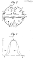
- Fig. 3 illustrates a microwave cavity 2' according to said further embodiment, which is arranged to be supplied with microwave energy from the schematically illustrated microwave generator 1.
- the cavity 2' incorporates centrally located openings 3', 4' intended for passage of a tube 5 in the opposite side surfaces 6', 7' or end surfaces of the cavity 2'.
- the cavity 2' has a peripherally extending constriction 23, seen in the section illustrated in Fig. 3, this section extending through the longitudinal axis of the cavity 2', said axis extending through said openings 3', 4'.
- the constriction 23 is located in the central part of the cavity. At the location of the constriction the radial distance from the geometric centre 25 of the cavity to the cavity wall is shorter than at the locations on both sides of the constriction 23.
- the cavity is also so formed as to be axially symmetrical around said longitudinal axis 24.
- the cavity is spherical, or substantially spherical with the exception of the location of the constriction 23, as evident from Fig. 1.
- Fig. 4 illustrates curves representative of the thermal power developed per unit volume (P) of a tube at present in the cavity, along the length (L) of said cavity. Therespective positions of the openings 3',4' are identified by the numerals 3' and 4' in Fig. 4.
- a power distribution P according to the broken-line curve 26 is obtained.
- a cavity provides a power distribution which is relatively dispersed over the length of the cavity, and with a short maximum in the direction of the longitudinal axis of the cavity.
- the total power supplied to the cavity must be limited in order to prevent electrical arcing, it is difficult to supply a sufficiently high power to insufficiently heated parts of the tube in the zone Z, since a large part of the power input is supplied to the tube parts located outside the zone Z. Since the dielectric losses of glass increase considerably with temperature, the power supplied is converted into heat at mainly the hot parts of the tube.
- the curve 27 is produced by means of the aforedescribed cavity 2'.
- the result of the constriction 23 is namely to concentrate the electrical field strength inwardly of the said constriction, in a manner such that the maximum of the electrical field strength is forced in towards the centre of the cavity, and is therewith higher in that part of the glass tube located within the zone Z than in those parts of the glass tube located outside said zone.
- the length of the zone Z thus corresponds to the axial length of the constriction 23.
- the extension of the aforesaid constriction 23 in the direction of said longitudinal axis is 1/4 to'1/2 of the average diameter of the cavity.
- the cavity wall 28 has in the location of said constriction an inner surface 29 of circular-arcuate configuration, the centre of which coincides with the geometric centre 25 of the cavity 2'.
- the cylindrical cavity 2, or the inner surface of the walls of the spherical cavity 2' are highly polished or coated with a highly reflective material which is inert to gases entering the cavity and which will not undergo any form of chemical conversion at the prevailing temperatures of the cavity walls.
- Gold is a material preferred in this respect, although any other suitable material can be used.
- the inner surfaces of the cavity will effectively reflect heat radiation 30 emitted by the tube and focus this radiation towards the centre 25 of the cavity, or in all events towards the zone Z.
- Such an embodiment has been found particularly effective, it being possible to reduce the total power input considerably in achieving high temperatures.
- the microwave cavity traverses along the glass tube during the heating stage.
- the Q-value is almost exclusively dependent on the geometry and temperature of the tube. Consequently, the cavity and energy connection should be adapted in a known manner to the dimensions of those tubes to be heated in the apparatus.
Landscapes
- Chemical & Material Sciences (AREA)
- Engineering & Computer Science (AREA)
- Materials Engineering (AREA)
- Organic Chemistry (AREA)
- Chemical Kinetics & Catalysis (AREA)
- General Chemical & Material Sciences (AREA)
- Life Sciences & Earth Sciences (AREA)
- General Life Sciences & Earth Sciences (AREA)
- Geochemistry & Mineralogy (AREA)
- Manufacturing & Machinery (AREA)
- Manufacture, Treatment Of Glass Fibers (AREA)
Priority Applications (1)
| Application Number | Priority Date | Filing Date | Title |
|---|---|---|---|
| AT85850214T ATE41138T1 (de) | 1984-07-03 | 1985-06-20 | Verfahren und vorrichtung zum erhitzen von dickwandigen glasrohren. |
Applications Claiming Priority (4)
| Application Number | Priority Date | Filing Date | Title |
|---|---|---|---|
| SE8403529 | 1984-07-03 | ||
| SE8403529A SE442989B (sv) | 1984-07-03 | 1984-07-03 | Forfarande och anordning for uppvermning av tjockveggiga glasror, serskilt kvartsror for framstellning av optiska fibrer, under utnyttjande av mikrovagsenergi |
| SE8502746A SE443973B (sv) | 1985-06-03 | 1985-06-03 | Mikrovagskavitet for att uppverma tjockveggiga glasror |
| SE8502746 | 1985-06-03 |
Publications (3)
| Publication Number | Publication Date |
|---|---|
| EP0173659A2 true EP0173659A2 (de) | 1986-03-05 |
| EP0173659A3 EP0173659A3 (en) | 1986-11-12 |
| EP0173659B1 EP0173659B1 (de) | 1989-03-08 |
Family
ID=26658752
Family Applications (1)
| Application Number | Title | Priority Date | Filing Date |
|---|---|---|---|
| EP85850214A Expired EP0173659B1 (de) | 1984-07-03 | 1985-06-20 | Verfahren und Vorrichtung zum Erhitzen von dickwandigen Glasrohren |
Country Status (7)
| Country | Link |
|---|---|
| US (1) | US4838915A (de) |
| EP (1) | EP0173659B1 (de) |
| AU (1) | AU580074B2 (de) |
| CA (1) | CA1241698A (de) |
| DE (1) | DE3568570D1 (de) |
| DK (1) | DK299985A (de) |
| FI (1) | FI78060C (de) |
Cited By (5)
| Publication number | Priority date | Publication date | Assignee | Title |
|---|---|---|---|---|
| EP0261742A1 (de) * | 1986-09-26 | 1988-03-30 | Philips Patentverwaltung GmbH | Verfahren und Vorrichtung zum Innenbeschichten von Rohren |
| EP0216739A3 (en) * | 1985-09-27 | 1988-05-11 | Stiftelsen Institutet For Mikrovagsteknik Vid Tekniska Hogskolan I Stockholm | A method and an apparatus for heating glass tubes |
| EP0270157A1 (de) * | 1986-11-17 | 1988-06-08 | Koninklijke Philips Electronics N.V. | Vorrichtung zum Anbringen von Glasschichten auf der Innenseite eines Rohres |
| EP0325227A3 (en) * | 1988-01-18 | 1990-07-25 | Sumitomo Electric Industries, Limited | Method of heating a quartz glass tube |
| EP0554845A1 (de) * | 1992-02-06 | 1993-08-11 | CeramOptec GmbH | Verfahren und Vorrichtung zum Herstellen von aussenbeschichteten Glaskörpern zur Herstellung von Lichtwellenleitern |
Families Citing this family (8)
| Publication number | Priority date | Publication date | Assignee | Title |
|---|---|---|---|---|
| DE69608746T2 (de) * | 1995-09-07 | 2000-10-12 | Ford Motor Co | Verfahren zum Erhitzen einer Glasscheibe |
| EP0761614B1 (de) * | 1995-09-07 | 2000-06-07 | Ford Motor Company | Verfahren zum Erhitzen, Formen und Härten einer Glasscheibe |
| US5656053A (en) * | 1995-09-07 | 1997-08-12 | Ford Motor Company | Method for heating and forming a glass sheet |
| US5847355A (en) * | 1996-01-05 | 1998-12-08 | California Institute Of Technology | Plasma-assisted microwave processing of materials |
| US6408649B1 (en) * | 2000-04-28 | 2002-06-25 | Gyrotron Technology, Inc. | Method for the rapid thermal treatment of glass and glass-like materials using microwave radiation |
| DE10225618A1 (de) * | 2002-06-07 | 2004-01-08 | Schott Glas | Verfahren zur Herstellung von Bauteilen mit langgestreckten Strukturen |
| SE521315C2 (sv) * | 2001-12-17 | 2003-10-21 | A Cell Acetyl Cellulosics | Mikrovågssystem för uppvärmning av voluminösa långsträckta laster |
| FI123122B (fi) * | 2009-02-16 | 2012-11-15 | Optogear Oy | Laitteisto lasimateriaalin valmistamiseksi |
Family Cites Families (14)
| Publication number | Priority date | Publication date | Assignee | Title |
|---|---|---|---|---|
| FR2249847A1 (en) * | 1973-11-06 | 1975-05-30 | Thomson Csf | Glass fibre pulling system - in which glass rod end is heated in resonance cavity of UHF waveguide |
| US4145456A (en) * | 1974-09-14 | 1979-03-20 | Dieter Kuppers | Method of producing internally coated glass tubes for the drawing of fibre optic light conductors |
| FR2288958A1 (fr) * | 1974-10-21 | 1976-05-21 | Desmarquest & Cec | Installation pour le traitement par zone de produits de forme allongee |
| US4144434A (en) * | 1976-06-14 | 1979-03-13 | Societe Lignes Telegraphiques Et Telephoniques | Microwave heating devices |
| CA1080562A (en) * | 1977-02-10 | 1980-07-01 | Frederick D. King | Method of and apparatus for manufacturing an optical fibre with plasma activated deposition in a tube |
| US4292063A (en) * | 1980-05-05 | 1981-09-29 | Northern Telecom Limited | Manufacture of an optical fiber preform with micro-wave plasma activated deposition in a tube |
| US4417911A (en) * | 1981-02-27 | 1983-11-29 | Associated Electrical Industries Limited | Manufacture of optical fibre preforms |
| NL8102149A (nl) * | 1981-05-01 | 1982-12-01 | Philips Nv | Werkwijze en inrichting voor de inwendige bedekking van een buis door reactieve afscheiding uit een gasmengsel onder invloed van een plasma. |
| FR2505472B1 (fr) * | 1981-05-05 | 1988-01-08 | Lignes Telegraph Telephon | Dispositif de concentration d'energie infrarouge et dispositif de fabrication de fibres optiques comportant un tel dispositif de concentration |
| NL8103648A (nl) * | 1981-08-03 | 1983-03-01 | Philips Nv | Werkwijze voor de vervaardiging van voorvormen voor het trekken van optische vezels en voorvormen volgens deze werkwijze verkregen en inrichting voor het continu vervaardigen van optische vezels. |
| US4446348A (en) * | 1982-03-29 | 1984-05-01 | E. I. Du Pont De Nemours And Company | Serpentine microwave applicator |
| US4477707A (en) * | 1982-11-24 | 1984-10-16 | General Electric Company | Electromagnetic field heating apparatus for curing resin/fiber composites in continuous pultrusion processes |
| US4718929A (en) * | 1983-10-21 | 1988-01-12 | Corning Glass Works | Vapor phase method for making metal halide glasses |
| SE448297B (sv) * | 1985-09-27 | 1987-02-09 | Stiftelsen Inst Mikrovags | Forfarande och anordning for uppvermning av glasror |
-
1985
- 1985-06-20 EP EP85850214A patent/EP0173659B1/de not_active Expired
- 1985-06-20 DE DE8585850214T patent/DE3568570D1/de not_active Expired
- 1985-06-27 CA CA000485744A patent/CA1241698A/en not_active Expired
- 1985-06-28 AU AU44297/85A patent/AU580074B2/en not_active Ceased
- 1985-07-02 FI FI852616A patent/FI78060C/fi not_active IP Right Cessation
- 1985-07-02 DK DK299985A patent/DK299985A/da not_active Application Discontinuation
-
1987
- 1987-11-16 US US07/120,782 patent/US4838915A/en not_active Expired - Lifetime
Cited By (6)
| Publication number | Priority date | Publication date | Assignee | Title |
|---|---|---|---|---|
| EP0216739A3 (en) * | 1985-09-27 | 1988-05-11 | Stiftelsen Institutet For Mikrovagsteknik Vid Tekniska Hogskolan I Stockholm | A method and an apparatus for heating glass tubes |
| EP0261742A1 (de) * | 1986-09-26 | 1988-03-30 | Philips Patentverwaltung GmbH | Verfahren und Vorrichtung zum Innenbeschichten von Rohren |
| US4877938A (en) * | 1986-09-26 | 1989-10-31 | U.S. Philips Corporation | Plasma activated deposition of an insulating material on the interior of a tube |
| EP0270157A1 (de) * | 1986-11-17 | 1988-06-08 | Koninklijke Philips Electronics N.V. | Vorrichtung zum Anbringen von Glasschichten auf der Innenseite eines Rohres |
| EP0325227A3 (en) * | 1988-01-18 | 1990-07-25 | Sumitomo Electric Industries, Limited | Method of heating a quartz glass tube |
| EP0554845A1 (de) * | 1992-02-06 | 1993-08-11 | CeramOptec GmbH | Verfahren und Vorrichtung zum Herstellen von aussenbeschichteten Glaskörpern zur Herstellung von Lichtwellenleitern |
Also Published As
| Publication number | Publication date |
|---|---|
| US4838915A (en) | 1989-06-13 |
| DE3568570D1 (en) | 1989-04-13 |
| FI78060C (fi) | 1989-06-12 |
| FI852616A0 (fi) | 1985-07-02 |
| EP0173659A3 (en) | 1986-11-12 |
| DK299985A (da) | 1986-01-04 |
| EP0173659B1 (de) | 1989-03-08 |
| AU4429785A (en) | 1986-01-09 |
| CA1241698A (en) | 1988-09-06 |
| AU580074B2 (en) | 1988-12-22 |
| FI78060B (fi) | 1989-02-28 |
| FI852616L (fi) | 1986-01-04 |
| DK299985D0 (da) | 1985-07-02 |
Similar Documents
| Publication | Publication Date | Title |
|---|---|---|
| EP0173659A2 (de) | Verfahren und Vorrichtung zum Erhitzen von dickwandigen Glasrohren | |
| US4760230A (en) | Method and an apparatus for heating glass tubes | |
| KR960002587B1 (ko) | 광예비 성형물을 슈트오버클래딩(soot overcladding)하는 방법 | |
| US4877938A (en) | Plasma activated deposition of an insulating material on the interior of a tube | |
| US6460378B1 (en) | Collapsing a multitube assembly and subsequent optical fiber drawing in the same furnace | |
| EP1060288B1 (de) | Pcvd-vorrichtung und verfahren zur herstellung einer optischen faser, eines vorform-stabes und eines mantelrohres und die damit hergestellte optische faser | |
| US4405655A (en) | Method and arrangement for internally coating a tube by reactive deposition from a gas mixture activated by a plasma | |
| US6701753B2 (en) | Method and apparatus for making improved optical fiber preforms and optical fiber therefrom | |
| US4144434A (en) | Microwave heating devices | |
| JPS632827A (ja) | 光ファイバの母材を製造する方法 | |
| US6715441B2 (en) | PCVD apparatus and a method of manufacturing an optical fiber, a preform rod and a jacket tube as well as the optical fiber manufactured therewith | |
| JPS62132739A (ja) | 光フアイバのプリフオ−ム製造法 | |
| US4740225A (en) | Method of producing optical fibers with noncircular core | |
| US4925473A (en) | Process and furnace for heat application | |
| US7734135B2 (en) | Method and device for manufacturing optical preforms, as well as the optical fibres obtained therewith | |
| EP0072069B1 (de) | Verfahren zur Herstellung von Vorformen zum Ziehen von optischen Fasern und Vorrichtung zur kontinuierlichen Herstellung von optischen Fasern | |
| JPS5922654A (ja) | 誘電ロツドを製造するためのプラズマ法 | |
| GB2149779A (en) | Manufacture of optical fibre preforms | |
| JPS63266798A (ja) | 線引き炉 | |
| US4778501A (en) | Process and furnace for heat application | |
| JPH0535097B2 (de) | ||
| EP0370001A1 (de) | Ofen und glasstreckverfahren. | |
| JPS55158146A (en) | Manufacture of optical fiber | |
| CN121248132A (zh) | 近常压微波等离子体管内法制备光纤预制棒的装置及方法 | |
| KR100456124B1 (ko) | 광섬유모재 제조를 위한 플라즈마 토치 |
Legal Events
| Date | Code | Title | Description |
|---|---|---|---|
| PUAI | Public reference made under article 153(3) epc to a published international application that has entered the european phase |
Free format text: ORIGINAL CODE: 0009012 |
|
| AK | Designated contracting states |
Kind code of ref document: A2 Designated state(s): AT BE CH DE FR GB IT LI LU NL |
|
| PUAL | Search report despatched |
Free format text: ORIGINAL CODE: 0009013 |
|
| AK | Designated contracting states |
Kind code of ref document: A3 Designated state(s): AT BE CH DE FR GB IT LI LU NL |
|
| 17P | Request for examination filed |
Effective date: 19861205 |
|
| 17Q | First examination report despatched |
Effective date: 19870811 |
|
| ITF | It: translation for a ep patent filed | ||
| GRAA | (expected) grant |
Free format text: ORIGINAL CODE: 0009210 |
|
| AK | Designated contracting states |
Kind code of ref document: B1 Designated state(s): AT BE CH DE FR GB IT LI LU NL |
|
| REF | Corresponds to: |
Ref document number: 41138 Country of ref document: AT Date of ref document: 19890315 Kind code of ref document: T |
|
| REF | Corresponds to: |
Ref document number: 3568570 Country of ref document: DE Date of ref document: 19890413 |
|
| ET | Fr: translation filed | ||
| PLBE | No opposition filed within time limit |
Free format text: ORIGINAL CODE: 0009261 |
|
| STAA | Information on the status of an ep patent application or granted ep patent |
Free format text: STATUS: NO OPPOSITION FILED WITHIN TIME LIMIT |
|
| 26N | No opposition filed | ||
| ITTA | It: last paid annual fee | ||
| PGFP | Annual fee paid to national office [announced via postgrant information from national office to epo] |
Ref country code: AT Payment date: 19920622 Year of fee payment: 8 |
|
| PGFP | Annual fee paid to national office [announced via postgrant information from national office to epo] |
Ref country code: NL Payment date: 19920630 Year of fee payment: 8 Ref country code: LU Payment date: 19920630 Year of fee payment: 8 |
|
| PGFP | Annual fee paid to national office [announced via postgrant information from national office to epo] |
Ref country code: BE Payment date: 19920706 Year of fee payment: 8 |
|
| EPTA | Lu: last paid annual fee | ||
| PG25 | Lapsed in a contracting state [announced via postgrant information from national office to epo] |
Ref country code: LU Free format text: LAPSE BECAUSE OF NON-PAYMENT OF DUE FEES Effective date: 19930620 Ref country code: AT Effective date: 19930620 |
|
| PG25 | Lapsed in a contracting state [announced via postgrant information from national office to epo] |
Ref country code: BE Effective date: 19930630 |
|
| REG | Reference to a national code |
Ref country code: CH Ref legal event code: PUE Owner name: TELEFONAKTIEBOLAGET LM ERICSSON |
|
| REG | Reference to a national code |
Ref country code: GB Ref legal event code: 732E |
|
| BERE | Be: lapsed |
Owner name: STIFTELSEN INSTITUTET FOR MIKROVAGSTEKNIK VID TEK Effective date: 19930630 |
|
| PG25 | Lapsed in a contracting state [announced via postgrant information from national office to epo] |
Ref country code: NL Effective date: 19940101 |
|
| NLV4 | Nl: lapsed or anulled due to non-payment of the annual fee | ||
| REG | Reference to a national code |
Ref country code: FR Ref legal event code: TP |
|
| REG | Reference to a national code |
Ref country code: GB Ref legal event code: IF02 |
|
| PGFP | Annual fee paid to national office [announced via postgrant information from national office to epo] |
Ref country code: GB Payment date: 20040616 Year of fee payment: 20 |
|
| PGFP | Annual fee paid to national office [announced via postgrant information from national office to epo] |
Ref country code: FR Payment date: 20040618 Year of fee payment: 20 |
|
| PGFP | Annual fee paid to national office [announced via postgrant information from national office to epo] |
Ref country code: CH Payment date: 20040621 Year of fee payment: 20 |
|
| PGFP | Annual fee paid to national office [announced via postgrant information from national office to epo] |
Ref country code: DE Payment date: 20040802 Year of fee payment: 20 |
|
| PG25 | Lapsed in a contracting state [announced via postgrant information from national office to epo] |
Ref country code: GB Free format text: LAPSE BECAUSE OF EXPIRATION OF PROTECTION Effective date: 20050619 |
|
| REG | Reference to a national code |
Ref country code: GB Ref legal event code: PE20 |
|
| REG | Reference to a national code |
Ref country code: CH Ref legal event code: PL |