EP0173343A2 - A solar ray energy collecting device - Google Patents
A solar ray energy collecting device Download PDFInfo
- Publication number
- EP0173343A2 EP0173343A2 EP85110963A EP85110963A EP0173343A2 EP 0173343 A2 EP0173343 A2 EP 0173343A2 EP 85110963 A EP85110963 A EP 85110963A EP 85110963 A EP85110963 A EP 85110963A EP 0173343 A2 EP0173343 A2 EP 0173343A2
- Authority
- EP
- European Patent Office
- Prior art keywords
- light
- ray energy
- collecting device
- solar ray
- energy collecting
- Prior art date
- Legal status (The legal status is an assumption and is not a legal conclusion. Google has not performed a legal analysis and makes no representation as to the accuracy of the status listed.)
- Withdrawn
Links
Images
Classifications
-
- G—PHYSICS
- G02—OPTICS
- G02B—OPTICAL ELEMENTS, SYSTEMS OR APPARATUS
- G02B3/00—Simple or compound lenses
- G02B3/02—Simple or compound lenses with non-spherical faces
- G02B3/08—Simple or compound lenses with non-spherical faces with discontinuous faces, e.g. Fresnel lens
-
- G—PHYSICS
- G02—OPTICS
- G02B—OPTICAL ELEMENTS, SYSTEMS OR APPARATUS
- G02B6/00—Light guides; Structural details of arrangements comprising light guides and other optical elements, e.g. couplings
- G02B6/24—Coupling light guides
- G02B6/26—Optical coupling means
- G02B6/262—Optical details of coupling light into, or out of, or between fibre ends, e.g. special fibre end shapes or associated optical elements
-
- A—HUMAN NECESSITIES
- A01—AGRICULTURE; FORESTRY; ANIMAL HUSBANDRY; HUNTING; TRAPPING; FISHING
- A01G—HORTICULTURE; CULTIVATION OF VEGETABLES, FLOWERS, RICE, FRUIT, VINES, HOPS OR SEAWEED; FORESTRY; WATERING
- A01G7/00—Botany in general
- A01G7/04—Electric or magnetic or acoustic treatment of plants for promoting growth
- A01G7/045—Electric or magnetic or acoustic treatment of plants for promoting growth with electric lighting
-
- A—HUMAN NECESSITIES
- A01—AGRICULTURE; FORESTRY; ANIMAL HUSBANDRY; HUNTING; TRAPPING; FISHING
- A01G—HORTICULTURE; CULTIVATION OF VEGETABLES, FLOWERS, RICE, FRUIT, VINES, HOPS OR SEAWEED; FORESTRY; WATERING
- A01G9/00—Cultivation in receptacles, forcing-frames or greenhouses; Edging for beds, lawn or the like
- A01G9/24—Devices or systems for heating, ventilating, regulating temperature, illuminating, or watering, in greenhouses, forcing-frames, or the like
- A01G9/249—Lighting means
-
- F—MECHANICAL ENGINEERING; LIGHTING; HEATING; WEAPONS; BLASTING
- F21—LIGHTING
- F21S—NON-PORTABLE LIGHTING DEVICES; SYSTEMS THEREOF; VEHICLE LIGHTING DEVICES SPECIALLY ADAPTED FOR VEHICLE EXTERIORS
- F21S11/00—Non-electric lighting devices or systems using daylight
-
- F—MECHANICAL ENGINEERING; LIGHTING; HEATING; WEAPONS; BLASTING
- F24—HEATING; RANGES; VENTILATING
- F24S—SOLAR HEAT COLLECTORS; SOLAR HEAT SYSTEMS
- F24S23/00—Arrangements for concentrating solar-rays for solar heat collectors
- F24S23/12—Light guides
-
- F—MECHANICAL ENGINEERING; LIGHTING; HEATING; WEAPONS; BLASTING
- F24—HEATING; RANGES; VENTILATING
- F24S—SOLAR HEAT COLLECTORS; SOLAR HEAT SYSTEMS
- F24S23/00—Arrangements for concentrating solar-rays for solar heat collectors
- F24S23/30—Arrangements for concentrating solar-rays for solar heat collectors with lenses
- F24S23/31—Arrangements for concentrating solar-rays for solar heat collectors with lenses having discontinuous faces, e.g. Fresnel lenses
-
- G—PHYSICS
- G02—OPTICS
- G02B—OPTICAL ELEMENTS, SYSTEMS OR APPARATUS
- G02B5/00—Optical elements other than lenses
- G02B5/08—Mirrors
-
- G—PHYSICS
- G02—OPTICS
- G02B—OPTICAL ELEMENTS, SYSTEMS OR APPARATUS
- G02B6/00—Light guides; Structural details of arrangements comprising light guides and other optical elements, e.g. couplings
- G02B6/0001—Light guides; Structural details of arrangements comprising light guides and other optical elements, e.g. couplings specially adapted for lighting devices or systems
- G02B6/0005—Light guides; Structural details of arrangements comprising light guides and other optical elements, e.g. couplings specially adapted for lighting devices or systems the light guides being of the fibre type
- G02B6/0006—Coupling light into the fibre
-
- G—PHYSICS
- G02—OPTICS
- G02B—OPTICAL ELEMENTS, SYSTEMS OR APPARATUS
- G02B6/00—Light guides; Structural details of arrangements comprising light guides and other optical elements, e.g. couplings
- G02B6/24—Coupling light guides
- G02B6/26—Optical coupling means
- G02B6/32—Optical coupling means having lens focusing means positioned between opposed fibre ends
-
- Y—GENERAL TAGGING OF NEW TECHNOLOGICAL DEVELOPMENTS; GENERAL TAGGING OF CROSS-SECTIONAL TECHNOLOGIES SPANNING OVER SEVERAL SECTIONS OF THE IPC; TECHNICAL SUBJECTS COVERED BY FORMER USPC CROSS-REFERENCE ART COLLECTIONS [XRACs] AND DIGESTS
- Y02—TECHNOLOGIES OR APPLICATIONS FOR MITIGATION OR ADAPTATION AGAINST CLIMATE CHANGE
- Y02E—REDUCTION OF GREENHOUSE GAS [GHG] EMISSIONS, RELATED TO ENERGY GENERATION, TRANSMISSION OR DISTRIBUTION
- Y02E10/00—Energy generation through renewable energy sources
- Y02E10/40—Solar thermal energy, e.g. solar towers
-
- Y—GENERAL TAGGING OF NEW TECHNOLOGICAL DEVELOPMENTS; GENERAL TAGGING OF CROSS-SECTIONAL TECHNOLOGIES SPANNING OVER SEVERAL SECTIONS OF THE IPC; TECHNICAL SUBJECTS COVERED BY FORMER USPC CROSS-REFERENCE ART COLLECTIONS [XRACs] AND DIGESTS
- Y02—TECHNOLOGIES OR APPLICATIONS FOR MITIGATION OR ADAPTATION AGAINST CLIMATE CHANGE
- Y02P—CLIMATE CHANGE MITIGATION TECHNOLOGIES IN THE PRODUCTION OR PROCESSING OF GOODS
- Y02P60/00—Technologies relating to agriculture, livestock or agroalimentary industries
- Y02P60/12—Technologies relating to agriculture, livestock or agroalimentary industries using renewable energies, e.g. solar water pumping
-
- Y—GENERAL TAGGING OF NEW TECHNOLOGICAL DEVELOPMENTS; GENERAL TAGGING OF CROSS-SECTIONAL TECHNOLOGIES SPANNING OVER SEVERAL SECTIONS OF THE IPC; TECHNICAL SUBJECTS COVERED BY FORMER USPC CROSS-REFERENCE ART COLLECTIONS [XRACs] AND DIGESTS
- Y02—TECHNOLOGIES OR APPLICATIONS FOR MITIGATION OR ADAPTATION AGAINST CLIMATE CHANGE
- Y02P—CLIMATE CHANGE MITIGATION TECHNOLOGIES IN THE PRODUCTION OR PROCESSING OF GOODS
- Y02P60/00—Technologies relating to agriculture, livestock or agroalimentary industries
- Y02P60/14—Measures for saving energy, e.g. in green houses
-
- Y—GENERAL TAGGING OF NEW TECHNOLOGICAL DEVELOPMENTS; GENERAL TAGGING OF CROSS-SECTIONAL TECHNOLOGIES SPANNING OVER SEVERAL SECTIONS OF THE IPC; TECHNICAL SUBJECTS COVERED BY FORMER USPC CROSS-REFERENCE ART COLLECTIONS [XRACs] AND DIGESTS
- Y10—TECHNICAL SUBJECTS COVERED BY FORMER USPC
- Y10S—TECHNICAL SUBJECTS COVERED BY FORMER USPC CROSS-REFERENCE ART COLLECTIONS [XRACs] AND DIGESTS
- Y10S47/00—Plant husbandry
- Y10S47/06—Plant growth regulation by control of light thereon
Definitions
- the present invention relates to a solar ray energy collecting device capable of effectively separating and collecting only a light component of a desired wave length among the solar rays.
- the present applicant has previously proposed various ways to focus solar rays or artificial light rays by use of lenses or the like, to guide the same into an optical conductor, and thereby to transmit them onto an optional desired place through the optical conductor for use in illumination or for other like purposes.
- the present applicant has previously proposed in the other ways a light focusing lens capable of effectively separating and taking out only a light component of a desired wave length among the solar rays in consideration of the actual situation as mentioned above.
- the primary object of the present invention is to provide a solar ray energy collecting device capable of effectively separating and collecting only a light component of a desired wave length among the solar rays.
- Fig. 1 is a construction view for explaining a light focusing lens which has been previously proposed by the present applicant.
- 10 is a Fresnel lens
- 11 is a light intercepting membrane mounted on the central portion of the Fresnel lens 11.
- the solar rays or the artificial light rays arrive directly at the points; a, b, c and d, of the lens 10 are focused, respectively, as shown in Fig. 1.
- the green light rays are shown by solid lines, the red light rays by dotted lines, and the blue light rays by two-dots-and-dash lines, respectively. Therefore, at the portion A of the plane I in Fig. 1 comparatively pure green light rays are concentrated, at the portion B of the plane II comparatively pure red light rays, and at the portion E of the plane III comparatively pure blue light rays. Consequently, if each light-receiving edge of the optical conductors is put at those portions; A, B and E, respectively, the light rays having only the desired light component can be guided into the optical conductor.
- the portion C is a blue light component area
- the portion D is a green light component area. It has been described, heretofore, that the light-receiving edge of the optical conductor is moved to the direction of the lens' optical axis so as to take out the light component of a desired wave length.
- the light component guided into the optical conductor can be also changed in accordance with the diameter of the optical conductor. For instance, if the diameter of the optical conductor is equal to F on the plane I, the visible light rays containing the light components from red to blue are guided into the optical conductor.
- Fig. 2 is a cross-sectional view showing another embodiment of the afore-mentioned light focusing lens.
- a light focusing lens 10 has a central portion 10a formed in a state of plane surface, and a light intercepting member 11 is mounted on the plane portion thereof.
- the plane portion 10a can be formed at the same time when the lens is formed, and thereby the dimension and location of the light intercepting member can be determined precisely.
- the surface for mounting the light intercepting member thereon is plane, it will be very easy to form a light intercepting membrane 11.
- the lens is not heated at all. Consequently, there is less fear that the lens is not deformed due to the heat. It is very preferable.
- the light intercepting member is not limited to the reflector.
- a light absorbing material, a photoelectric converter, or the like can be used instead of the reflector.
- the photoelectric converter when used, the solar ray energy can be utilized much more effectively.
- Fig. 3 is a construction view for explaining an embodiment of the solar ray energy collecting device according to the present invention.
- 10 is a light focusing lens as mentioned above, 11 a light intercepting member, 12 an optical conductor, 13 a reflection member put on the outside surface at the light-receiving side of the optical conductor 12, 14 a photoelectric converter for converting the light energy reflected by the reflection member 13 to the electric energy, and 15 a photothermal converter for converting the light energy to the thermal energy.
- the solid line shows visible light rays, the dotted line infrared rays, and the two-dots-and-dash line ultraviolet rays, respectively.
- the light-receiving edge 12a of the optical conductor 12 is placed, for instance, on the focus position of the visible light rays' component. Consequently, only the visible light rays' component among the solar rays' components is guided into the optical conductor 12 and transmitted through the optical conductor to an optional desired place for use in illumination or the other like purposes.
- the infrared rays' component among the solar rays' components arrives at the reflection member 13, and the light rays of the infrared rays' component are reflected thereon and supplied to the photoelectric converter 14, and therefore the photoelectric converter 14 can obtain an electric energy by effectively utilizing the infrared rays' component of the solar rays.
- the photothermal converter 15 is put on a place that receives the ultraviolet rays. In such a manner, even the ultraviolet rays' component of the solar rays can be effectively utilized.
- an inductive substance which accumulates energy. by the action of the optical reaction due to the light energy can be used for example.
- Fig. 4 is a cross-sectional view showing another embodiment of the light-receiving edge portion of the optical conductor 12.
- 16 is a conical optical conductor having a wide area of the light-receiving edge.
- a cylindrical hollow body is employed as a reflection member 13.
- a light intercepting member 11 is used, as mentioned above, on the central portion of the light focusing lens 10.
- the photoelectric converter can be easily installed.
- a desired wave length component can be separated from the solar rays' components and taken out, and thereby it can be most effectively utilized in accordance with the wave length component. In consequence, the all-over utilization efficiency of the solar energy can be considerably improved.
Landscapes
- Physics & Mathematics (AREA)
- Engineering & Computer Science (AREA)
- Life Sciences & Earth Sciences (AREA)
- Sustainable Development (AREA)
- Optics & Photonics (AREA)
- General Physics & Mathematics (AREA)
- General Engineering & Computer Science (AREA)
- Mechanical Engineering (AREA)
- Combustion & Propulsion (AREA)
- Chemical & Material Sciences (AREA)
- Thermal Sciences (AREA)
- Sustainable Energy (AREA)
- Environmental Sciences (AREA)
- Biodiversity & Conservation Biology (AREA)
- Botany (AREA)
- Ecology (AREA)
- Forests & Forestry (AREA)
- Photovoltaic Devices (AREA)
Abstract
Description
- The present invention relates to a solar ray energy collecting device capable of effectively separating and collecting only a light component of a desired wave length among the solar rays.
- The present applicant has previously proposed various ways to focus solar rays or artificial light rays by use of lenses or the like, to guide the same into an optical conductor, and thereby to transmit them onto an optional desired place through the optical conductor for use in illumination or for other like purposes.
- However, in the case of employing the light energy transmitted through the optical conductor in such a manner as mentioned above as a photo-synthesis light source for nurturing chlorella or intensively cultivate the plants, a light source for breeding fish, a light source for promoting human health, and a light source utilized for various other purposes, there are many cases in which only a desired light component fitted in the purpose of utilization needs to be selectively separated and employed among the light components contained in the light energies.
- However, although various techniques of cutting off infrared rays, ultraviolet rays, or the like have already been proposed up to now, a technique of taking out a light component of the specially designated wave length among the white light rays has not yet been proposed at all. Furthermore, it was very difficult to obtain the infrared rays, the ultraviolet rays, or the like which contain no visible light rays' component or very small amount of component of those visible rays.
- The present applicant has previously proposed in the other ways a light focusing lens capable of effectively separating and taking out only a light component of a desired wave length among the solar rays in consideration of the actual situation as mentioned above.
- The primary object of the present invention is to provide a solar ray energy collecting device capable of effectively separating and collecting only a light component of a desired wave length among the solar rays.
- It is another object of the present invention to provide a solar ray energy collecting device in which a specially designated wave length component among the solar rays energies can be utilized as the light energy and the other wave length components can be utilized as the thermal energy or the electric energy.
- It is another object of the present invention to provide a solar ray energy collecting device in which a desired wave length component can be separated from the solar rays' components and taken out, and thereby it can be most effectively utilized in accordance with the wave length component.
- The above-mentioned features and other advantages of the present invention will be apparent from the following detailed description which goes with the accompanying drawings.
-
- Figs. 1 and 2 are views showing the light focusing lenses employed in the present invention, respectively.
- Fig. 3 is a construction view for explaining an embodiment of the solar ray energy collecting device according to the present invention; and
- Fig. 4 is a cross-sectional view for explaining another embodiment in which the focused solar rays are guided into the optical conductor;
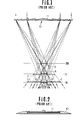
- Fig. 1 is a construction view for explaining a light focusing lens which has been previously proposed by the present applicant. In Fig. 1, 10 is a Fresnel lens, and 11 is a light intercepting membrane mounted on the central portion of the Fresnel lens 11. The solar rays or the artificial light rays arrive directly at the points; a, b, c and d, of the
lens 10 are focused, respectively, as shown in Fig. 1. - Moreover, in Fig. 1, the green light rays are shown by solid lines, the red light rays by dotted lines, and the blue light rays by two-dots-and-dash lines, respectively. Therefore, at the portion A of the plane I in Fig. 1 comparatively pure green light rays are concentrated, at the portion B of the plane II comparatively pure red light rays, and at the portion E of the plane III comparatively pure blue light rays. Consequently, if each light-receiving edge of the optical conductors is put at those portions; A, B and E, respectively, the light rays having only the desired light component can be guided into the optical conductor.
- Moreover, on the plane II, the portion C is a blue light component area, and the portion D is a green light component area. It has been described, heretofore, that the light-receiving edge of the optical conductor is moved to the direction of the lens' optical axis so as to take out the light component of a desired wave length. However, the light component guided into the optical conductor can be also changed in accordance with the diameter of the optical conductor. For instance, if the diameter of the optical conductor is equal to F on the plane I, the visible light rays containing the light components from red to blue are guided into the optical conductor.
- Fig. 2 is a cross-sectional view showing another embodiment of the afore-mentioned light focusing lens. In Fig. 2, a
light focusing lens 10 has acentral portion 10a formed in a state of plane surface, and a light intercepting member 11 is mounted on the plane portion thereof. In relation to such a light focusing lens, theplane portion 10a can be formed at the same time when the lens is formed, and thereby the dimension and location of the light intercepting member can be determined precisely. And further, since the surface for mounting the light intercepting member thereon is plane, it will be very easy to form a light intercepting membrane 11. - Moreover, in the case of employing a reflector as the light intercepting member, the lens is not heated at all. Consequently, there is less fear that the lens is not deformed due to the heat. It is very preferable. In case that there is no fear of being heated, the light intercepting member is not limited to the reflector. A light absorbing material, a photoelectric converter, or the like can be used instead of the reflector. However, when the photoelectric converter is used, the solar ray energy can be utilized much more effectively.
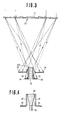
- Fig. 3 is a construction view for explaining an embodiment of the solar ray energy collecting device according to the present invention. In Fig. 3, 10 is a light focusing lens as mentioned above, 11 a light intercepting member, 12 an optical conductor, 13 a reflection member put on the outside surface at the light-receiving side of the
optical conductor 12, 14 a photoelectric converter for converting the light energy reflected by thereflection member 13 to the electric energy, and 15 a photothermal converter for converting the light energy to the thermal energy. - In Fig. 3, on that occasion, the solid line shows visible light rays, the dotted line infrared rays, and the two-dots-and-dash line ultraviolet rays, respectively. The light-
receiving edge 12a of theoptical conductor 12 is placed, for instance, on the focus position of the visible light rays' component. Consequently, only the visible light rays' component among the solar rays' components is guided into theoptical conductor 12 and transmitted through the optical conductor to an optional desired place for use in illumination or the other like purposes. - On the other hand, the infrared rays' component among the solar rays' components arrives at the
reflection member 13, and the light rays of the infrared rays' component are reflected thereon and supplied to thephotoelectric converter 14, and therefore thephotoelectric converter 14 can obtain an electric energy by effectively utilizing the infrared rays' component of the solar rays. And, thephotothermal converter 15 is put on a place that receives the ultraviolet rays. In such a manner, even the ultraviolet rays' component of the solar rays can be effectively utilized. Moreover, as thephotothermal converter 15, an inductive substance which accumulates energy. by the action of the optical reaction due to the light energy can be used for example. - Fig. 4 is a cross-sectional view showing another embodiment of the light-receiving edge portion of the
optical conductor 12. In Fig. 4, 16 is a conical optical conductor having a wide area of the light-receiving edge. In such a manner, it will be possible to make the diameter of theoptical conductor 12 small and thereby to reduce the cost for producing the optical conductor to a large extent. However, on that occasion, a cylindrical hollow body is employed as areflection member 13. Moreover, a light intercepting member 11 is used, as mentioned above, on the central portion of thelight focusing lens 10. In the case of employing the photoelectric converter as the light intercepting member, the solar energy can be utilized much more effectively. On that occasion, if the lens having a plane surface on the central portion thereof is employed, the photoelectric converter can be easily installed. - As is apparent from the foregoing description, according to the present invention, a desired wave length component can be separated from the solar rays' components and taken out, and thereby it can be most effectively utilized in accordance with the wave length component. In consequence, the all-over utilization efficiency of the solar energy can be considerably improved.
Claims (11)
- (1) A solar ray energy collecting device, characterized in that said solar ray energy collecting device comprises a light focusing lens being provided with a light intercepting member on the central part thereof, an optical conductor having a light-receiving edge situated at the position of said lens' focus for focusing a specially designated light component, a reflector installed at the circumferential portion of said optical conductor, and means for collecting energy of the light component reflected by said reflector.
- (2) A solar ray energy collecting device as defined in Claim 1, characterized in that said light intercepting member is a light reflecting material.
- (3) A solar ray energy collecting device as defined in Claim 1, characterized in that said light intercepting member is a light absorbing material.
- (4) A solar ray energy collecting device as defined in Claim 1, characterized in that said light intercepting member is a photoelectric converter.
- (5) A solar ray energy collecting device as defined in Claim 1, characterized in that said specially designated light component is visible light rays.
- (6) A solar ray energy collecting device as defined in Claim 1, characterized in that said specially designated light component is a green light component.
- (7) A solar ray energy collecting device as defined in Claim 1, characterized in that said means for collecting energy of the light component reflected by said reflector is a photoelectric converter.
- (8) A solar ray energy collecting device as defined in Claim 1, characterized in that said solar ray energy collecting device further comprises means for collecting energy of the light component having a focus shorter than said focus position among the solar rays focused by said light focusing lens.
- (9) A solar ray energy collecting device as defined in Claim 8, characterized in that said means for collecting said solar ray energy is a photothermal converter.
- (10) A solar ray energy collecting device as defined in Claim 8, characterized in that said means for collecting said solar ray energy is an inductive substance which accumulates energy by the action of an optical reaction due to the optical energy.
- (11) A solar ray energy collecting device as defined in Claim 1, characterized in that said light-receiving edge of said optical conductor is connected with a tapering conical optical conductor having a wide area of the light-receiving edge, the outside surface of said conical portion of the optical conductor being covered with a cylindrical reflection member.
Applications Claiming Priority (2)
| Application Number | Priority Date | Filing Date | Title |
|---|---|---|---|
| JP183293/84 | 1984-08-31 | ||
| JP59183293A JPS6161125A (en) | 1984-08-31 | 1984-08-31 | Converging device of solar energy |
Publications (2)
| Publication Number | Publication Date |
|---|---|
| EP0173343A2 true EP0173343A2 (en) | 1986-03-05 |
| EP0173343A3 EP0173343A3 (en) | 1988-10-12 |
Family
ID=16133122
Family Applications (1)
| Application Number | Title | Priority Date | Filing Date |
|---|---|---|---|
| EP85110963A Withdrawn EP0173343A3 (en) | 1984-08-31 | 1985-08-30 | A solar ray energy collecting device |
Country Status (6)
| Country | Link |
|---|---|
| US (1) | US4653472A (en) |
| EP (1) | EP0173343A3 (en) |
| JP (1) | JPS6161125A (en) |
| KR (1) | KR890005221B1 (en) |
| AU (1) | AU573151B2 (en) |
| NZ (1) | NZ213178A (en) |
Cited By (4)
| Publication number | Priority date | Publication date | Assignee | Title |
|---|---|---|---|---|
| FR2625334A1 (en) * | 1987-12-28 | 1989-06-30 | Mori Kei | MECHANISM FOR POSITIONING THE PHOTORECEPTING END OF AN OPTICAL CONDUCTIVE CABLE AT THE FOCUS OF A LENS |
| FR2626966A1 (en) * | 1988-02-04 | 1989-08-11 | Kei Mori | SOLAR RAY SENSOR DEVICE |
| EP0390208A2 (en) * | 1989-03-31 | 1990-10-03 | Ichikoh Industries Limited | Projector-type head lamp for motor vehicles |
| CN105334609A (en) * | 2015-11-29 | 2016-02-17 | 交通运输部南海航海保障中心北海航标处 | Solar energy collecting device |
Families Citing this family (26)
| Publication number | Priority date | Publication date | Assignee | Title |
|---|---|---|---|---|
| JPS6078403A (en) * | 1983-10-04 | 1985-05-04 | Takashi Mori | Solar light collector for cosmic space |
| JPS6161101A (en) * | 1984-08-31 | 1986-03-28 | Takashi Mori | Condenser lens |
| JPS62137073A (en) * | 1985-12-10 | 1987-06-19 | 森 敬 | Solar ray irradiation remedy apparatus |
| JPS63158070A (en) * | 1986-12-22 | 1988-07-01 | 森 敬 | Light irradiation remedy apparatus |
| AU609107B2 (en) * | 1987-03-31 | 1991-04-26 | Arthur George Yarrington | Solar optic lamp |
| US5058316A (en) * | 1988-02-15 | 1991-10-22 | Shigenobu Watari | Method and apparatus for cultivating mushrooms |
| JPH02197005A (en) * | 1989-01-26 | 1990-08-03 | Takashi Mori | Solar lighting device |
| US5140469A (en) * | 1990-10-03 | 1992-08-18 | Raytheon Company | Illumination apparatus for semiconductor fabrication including conical optical means |
| JP3050271B2 (en) * | 1994-06-03 | 2000-06-12 | 和雄 吉野 | Solar concentrator |
| US6399874B1 (en) * | 2001-01-11 | 2002-06-04 | Charles Dennehy, Jr. | Solar energy module and fresnel lens for use in same |
| EP1261039A1 (en) * | 2001-05-23 | 2002-11-27 | Université de Liège | Solar concentrator |
| KR100420868B1 (en) * | 2001-09-29 | 2004-03-09 | 모인에너지(주) | Solar concentrator module |
| NL1026082C2 (en) * | 2004-04-29 | 2005-11-01 | Johannes Van Tilborgh | Greenhouse with daylight system. |
| US7439712B2 (en) * | 2006-02-21 | 2008-10-21 | Mccowen Clint | Energy collection |
| US8153888B2 (en) * | 2008-05-01 | 2012-04-10 | Northrop Grumman Systems Corporation | Lateral ultra-high efficiency solar cell |
| US20100175685A1 (en) * | 2008-07-14 | 2010-07-15 | Robert Owen Campbell | Advanced Tracking Concentrator Employing Rotating Input Arrangement and Method |
| CN101923209B (en) * | 2009-06-16 | 2013-06-05 | 鸿富锦精密工业(深圳)有限公司 | Light harvesting device |
| US7946286B2 (en) * | 2009-09-24 | 2011-05-24 | Genie Lens Technologies, Llc | Tracking fiber optic wafer concentrator |
| CN102770788A (en) * | 2010-12-01 | 2012-11-07 | 松下电器产业株式会社 | Fresnel-fly's eye microlens arrays for concentrating solar cell |
| KR101037698B1 (en) * | 2011-03-24 | 2011-05-27 | 주식회사 건기 | Transmitter of focusing sun light using by plastic optical fiber |
| US20110265378A1 (en) * | 2011-07-15 | 2011-11-03 | Kevin Callaway | Truncated Reflector |
| CN103399395A (en) * | 2013-08-16 | 2013-11-20 | 林建斌 | Conical collecting lens |
| US9331603B2 (en) | 2014-08-07 | 2016-05-03 | Ion Power Group, Llc | Energy collection |
| CN104365392A (en) * | 2014-08-25 | 2015-02-25 | 衢州中恒农业科技有限公司 | Lifting LED grow light device |
| US11162713B2 (en) | 2018-12-17 | 2021-11-02 | Blueshift, LLC | Light concentrator system for precision thermal processes |
| US20210180830A1 (en) * | 2019-12-16 | 2021-06-17 | The Boeing Company | Multi-focal point solar refraction heating |
Citations (8)
| Publication number | Priority date | Publication date | Assignee | Title |
|---|---|---|---|---|
| US2907249A (en) * | 1956-10-05 | 1959-10-06 | Electro Seal Corp | Lens for signal lights |
| US3902794A (en) * | 1974-01-02 | 1975-09-02 | Eugene Abrams | Fresnell lens |
| US4238246A (en) * | 1979-06-04 | 1980-12-09 | North American Utility Construction Corp. | Solar energy system with composite concentrating lenses |
| US4271820A (en) * | 1979-05-16 | 1981-06-09 | Danforth Holley | Solar heat structure |
| US4395582A (en) * | 1979-03-28 | 1983-07-26 | Gibbs & Hill, Inc. | Combined solar conversion |
| US4461278A (en) * | 1981-04-02 | 1984-07-24 | Kei Mori | Apparatus for collecting and transmitting solar energy |
| EP0122390A1 (en) * | 1983-02-14 | 1984-10-24 | Kei Mori | Light source for culturing plants |
| US4511755A (en) * | 1982-05-17 | 1985-04-16 | Kei Mori | Solar ray collection apparatus |
Family Cites Families (15)
| Publication number | Priority date | Publication date | Assignee | Title |
|---|---|---|---|---|
| JPS544622B1 (en) * | 1970-12-26 | 1979-03-08 | ||
| JPS539129A (en) * | 1976-07-13 | 1978-01-27 | Matsushita Electric Ind Co Ltd | Light branching system |
| US4106952A (en) * | 1977-09-09 | 1978-08-15 | Kravitz Jerome H | Solar panel unit |
| FR2404307A1 (en) * | 1977-09-27 | 1979-04-20 | Centre Nat Etd Spatiales | DOUBLE HETEROJUNCTION SOLAR CELLS AND MOUNTING DEVICE |
| US4201197A (en) * | 1978-03-20 | 1980-05-06 | Dismer Raymond H | Solar energy collector having a fiber-optic cable |
| DE2842400A1 (en) * | 1978-09-29 | 1980-04-17 | Ibm Deutschland | SOLAR ENERGY COLLECTOR WITH LENS GRID |
| US4284839A (en) * | 1978-12-18 | 1981-08-18 | Johnson Steven A | Internal refractor focusing solar energy collector apparatus and method |
| US4307936A (en) * | 1979-09-17 | 1981-12-29 | Tsurunosuke Ochiai | System for collecting solar energy |
| US4312330A (en) * | 1980-06-26 | 1982-01-26 | Swedlow, Inc. | Focusing device for concentrating radiation |
| US4411490A (en) * | 1980-08-18 | 1983-10-25 | Maurice Daniel | Apparatus for collecting, distributing and utilizing solar radiation |
| US4425907A (en) * | 1980-09-25 | 1984-01-17 | Exxon Research And Engineering Co. | Reflector-coupled fluorescent solar collector |
| US4483311A (en) * | 1981-09-21 | 1984-11-20 | Whitaker Ranald O | Solar power system utilizing optical fibers, each fiber fed by a respective lens |
| JPS5918420U (en) * | 1982-07-26 | 1984-02-04 | 株式会社村田製作所 | ceramic capacitor |
| JPS5958405A (en) * | 1982-09-29 | 1984-04-04 | Toshiba Electric Equip Corp | Natural lighting device |
| US4458672A (en) * | 1982-12-13 | 1984-07-10 | Wesley Richard S W | Thermal panel |
-
1984
- 1984-08-31 JP JP59183293A patent/JPS6161125A/en active Granted
-
1985
- 1985-08-16 KR KR1019850005911A patent/KR890005221B1/en not_active IP Right Cessation
- 1985-08-20 US US06/767,567 patent/US4653472A/en not_active Expired - Fee Related
- 1985-08-21 NZ NZ213178A patent/NZ213178A/en unknown
- 1985-08-23 AU AU46600/85A patent/AU573151B2/en not_active Ceased
- 1985-08-30 EP EP85110963A patent/EP0173343A3/en not_active Withdrawn
Patent Citations (8)
| Publication number | Priority date | Publication date | Assignee | Title |
|---|---|---|---|---|
| US2907249A (en) * | 1956-10-05 | 1959-10-06 | Electro Seal Corp | Lens for signal lights |
| US3902794A (en) * | 1974-01-02 | 1975-09-02 | Eugene Abrams | Fresnell lens |
| US4395582A (en) * | 1979-03-28 | 1983-07-26 | Gibbs & Hill, Inc. | Combined solar conversion |
| US4271820A (en) * | 1979-05-16 | 1981-06-09 | Danforth Holley | Solar heat structure |
| US4238246A (en) * | 1979-06-04 | 1980-12-09 | North American Utility Construction Corp. | Solar energy system with composite concentrating lenses |
| US4461278A (en) * | 1981-04-02 | 1984-07-24 | Kei Mori | Apparatus for collecting and transmitting solar energy |
| US4511755A (en) * | 1982-05-17 | 1985-04-16 | Kei Mori | Solar ray collection apparatus |
| EP0122390A1 (en) * | 1983-02-14 | 1984-10-24 | Kei Mori | Light source for culturing plants |
Cited By (5)
| Publication number | Priority date | Publication date | Assignee | Title |
|---|---|---|---|---|
| FR2625334A1 (en) * | 1987-12-28 | 1989-06-30 | Mori Kei | MECHANISM FOR POSITIONING THE PHOTORECEPTING END OF AN OPTICAL CONDUCTIVE CABLE AT THE FOCUS OF A LENS |
| FR2626966A1 (en) * | 1988-02-04 | 1989-08-11 | Kei Mori | SOLAR RAY SENSOR DEVICE |
| EP0390208A2 (en) * | 1989-03-31 | 1990-10-03 | Ichikoh Industries Limited | Projector-type head lamp for motor vehicles |
| EP0390208A3 (en) * | 1989-03-31 | 1991-10-23 | Ichikoh Industries Limited | Projector-type head lamp for motor vehicles |
| CN105334609A (en) * | 2015-11-29 | 2016-02-17 | 交通运输部南海航海保障中心北海航标处 | Solar energy collecting device |
Also Published As
| Publication number | Publication date |
|---|---|
| AU4660085A (en) | 1986-03-06 |
| NZ213178A (en) | 1989-03-29 |
| JPH0139083B2 (en) | 1989-08-18 |
| US4653472A (en) | 1987-03-31 |
| KR860002022A (en) | 1986-03-24 |
| AU573151B2 (en) | 1988-05-26 |
| EP0173343A3 (en) | 1988-10-12 |
| KR890005221B1 (en) | 1989-12-18 |
| JPS6161125A (en) | 1986-03-28 |
Similar Documents
| Publication | Publication Date | Title |
|---|---|---|
| EP0173343A2 (en) | A solar ray energy collecting device | |
| EP0062847B1 (en) | Apparatus for collecting and transmitting solar energy | |
| EP0069977A2 (en) | An optical radiator | |
| US4379613A (en) | Solar energy collector | |
| EP0115296B1 (en) | Artificial light source device | |
| JPH0332045B2 (en) | ||
| EP0173344A2 (en) | A light focusing lens | |
| AU597010B2 (en) | A light radiator | |
| KR890013435A (en) | Solar collector | |
| US4726642A (en) | Artificial light source device | |
| JPS5624305A (en) | Lighting device making use of solar light | |
| SE8703597D0 (en) | solar collection | |
| JPS5821205A (en) | Light radiator | |
| US4657353A (en) | Conical beam concentrator | |
| KR900002582Y1 (en) | A light focusing lens | |
| JPS57129348A (en) | Solar heat collector | |
| JPH02139802A (en) | Solar beam collecting device | |
| JPS6180114A (en) | Artificial light source device | |
| KR890000259Y1 (en) | Lens protective appaatus for colecting device of sun light | |
| EP0065045A1 (en) | A solar energy collection system | |
| JPS6245528B2 (en) | ||
| JPS5536808A (en) | Electric converting and connecting device of optical fiber | |
| JPS58171001A (en) | Photodetecting lens | |
| JPS58137802A (en) | Solar light collector | |
| JPS5796309A (en) | Optical fiber connecting device |
Legal Events
| Date | Code | Title | Description |
|---|---|---|---|
| PUAI | Public reference made under article 153(3) epc to a published international application that has entered the european phase |
Free format text: ORIGINAL CODE: 0009012 |
|
| AK | Designated contracting states |
Kind code of ref document: A2 Designated state(s): CH DE FR GB IT LI NL SE |
|
| PUAL | Search report despatched |
Free format text: ORIGINAL CODE: 0009013 |
|
| AK | Designated contracting states |
Kind code of ref document: A3 Designated state(s): CH DE FR GB IT LI NL SE |
|
| 17P | Request for examination filed |
Effective date: 19890412 |
|
| STAA | Information on the status of an ep patent application or granted ep patent |
Free format text: STATUS: THE APPLICATION HAS BEEN WITHDRAWN |
|
| 18W | Application withdrawn |
Withdrawal date: 19900531 |
|
| R18W | Application withdrawn (corrected) |
Effective date: 19900531 |