EP0172844B1 - A method and a device for testing the sealing of a combustion engine - Google Patents
A method and a device for testing the sealing of a combustion engine Download PDFInfo
- Publication number
- EP0172844B1 EP0172844B1 EP85900822A EP85900822A EP0172844B1 EP 0172844 B1 EP0172844 B1 EP 0172844B1 EP 85900822 A EP85900822 A EP 85900822A EP 85900822 A EP85900822 A EP 85900822A EP 0172844 B1 EP0172844 B1 EP 0172844B1
- Authority
- EP
- European Patent Office
- Prior art keywords
- cooling system
- engine
- measuring apparatus
- pressure
- testing
- Prior art date
- Legal status (The legal status is an assumption and is not a legal conclusion. Google has not performed a legal analysis and makes no representation as to the accuracy of the status listed.)
- Expired
Links
- 238000002485 combustion reaction Methods 0.000 title claims abstract description 20
- 238000000034 method Methods 0.000 title claims abstract description 14
- 238000012360 testing method Methods 0.000 title claims abstract description 12
- 238000007789 sealing Methods 0.000 title claims description 14
- 238000001816 cooling Methods 0.000 claims abstract description 50
- 239000012530 fluid Substances 0.000 claims description 4
- 238000009530 blood pressure measurement Methods 0.000 claims 1
- 238000005259 measurement Methods 0.000 abstract description 3
- 239000007789 gas Substances 0.000 description 13
- 239000000110 cooling liquid Substances 0.000 description 11
- UGFAIRIUMAVXCW-UHFFFAOYSA-N Carbon monoxide Chemical compound [O+]#[C-] UGFAIRIUMAVXCW-UHFFFAOYSA-N 0.000 description 2
- 229910002091 carbon monoxide Inorganic materials 0.000 description 2
- 230000006835 compression Effects 0.000 description 2
- 238000007906 compression Methods 0.000 description 2
- 230000007547 defect Effects 0.000 description 2
- 239000000446 fuel Substances 0.000 description 2
- 239000007788 liquid Substances 0.000 description 2
- 238000004458 analytical method Methods 0.000 description 1
- 238000004891 communication Methods 0.000 description 1
- 230000000694 effects Effects 0.000 description 1
- 238000010438 heat treatment Methods 0.000 description 1
- 238000013021 overheating Methods 0.000 description 1
- 230000000149 penetrating effect Effects 0.000 description 1
- 239000011148 porous material Substances 0.000 description 1
- 238000012545 processing Methods 0.000 description 1
- 238000012956 testing procedure Methods 0.000 description 1
- XLYOFNOQVPJJNP-UHFFFAOYSA-N water Substances O XLYOFNOQVPJJNP-UHFFFAOYSA-N 0.000 description 1
Images
Classifications
-
- F—MECHANICAL ENGINEERING; LIGHTING; HEATING; WEAPONS; BLASTING
- F02—COMBUSTION ENGINES; HOT-GAS OR COMBUSTION-PRODUCT ENGINE PLANTS
- F02B—INTERNAL-COMBUSTION PISTON ENGINES; COMBUSTION ENGINES IN GENERAL
- F02B77/00—Component parts, details or accessories, not otherwise provided for
- F02B77/08—Safety, indicating, or supervising devices
- F02B77/088—Safety, indicating, or supervising devices relating to tightness
-
- F—MECHANICAL ENGINEERING; LIGHTING; HEATING; WEAPONS; BLASTING
- F01—MACHINES OR ENGINES IN GENERAL; ENGINE PLANTS IN GENERAL; STEAM ENGINES
- F01P—COOLING OF MACHINES OR ENGINES IN GENERAL; COOLING OF INTERNAL-COMBUSTION ENGINES
- F01P11/00—Component parts, details, or accessories not provided for in, or of interest apart from, groups F01P1/00 - F01P9/00
- F01P11/02—Liquid-coolant filling, overflow, venting, or draining devices
- F01P11/0204—Filling
- F01P11/0209—Closure caps
- F01P11/0238—Closure caps with overpressure valves or vent valves
-
- F—MECHANICAL ENGINEERING; LIGHTING; HEATING; WEAPONS; BLASTING
- F01—MACHINES OR ENGINES IN GENERAL; ENGINE PLANTS IN GENERAL; STEAM ENGINES
- F01P—COOLING OF MACHINES OR ENGINES IN GENERAL; COOLING OF INTERNAL-COMBUSTION ENGINES
- F01P2023/00—Signal processing; Details thereof
-
- F—MECHANICAL ENGINEERING; LIGHTING; HEATING; WEAPONS; BLASTING
- F01—MACHINES OR ENGINES IN GENERAL; ENGINE PLANTS IN GENERAL; STEAM ENGINES
- F01P—COOLING OF MACHINES OR ENGINES IN GENERAL; COOLING OF INTERNAL-COMBUSTION ENGINES
- F01P2025/00—Measuring
- F01P2025/04—Pressure
-
- F—MECHANICAL ENGINEERING; LIGHTING; HEATING; WEAPONS; BLASTING
- F01—MACHINES OR ENGINES IN GENERAL; ENGINE PLANTS IN GENERAL; STEAM ENGINES
- F01P—COOLING OF MACHINES OR ENGINES IN GENERAL; COOLING OF INTERNAL-COMBUSTION ENGINES
- F01P2031/00—Fail safe
- F01P2031/18—Detecting fluid leaks
Definitions
- This invention relates to a method and a device for testing the sealing of an engine which comprises at least one combustion chamber and a cooling system containing a fluid.
- the sealing mentioned here is the one between the combustion chamber of the engine and the cooling system.
- a gas leakage between the combustion chamber of the engine and the cooling system can occur for instance as a result of defects of the cylinder head gasket or rifts and pores in the cylinder head or the engine block.
- Great leakages are naturally relatively easy to discover.
- a normal indication of such leakages is that the warm gases which are leaking into the cooling system cause such a heating of the cooling liquid that the cooling system no longer can hold the temperature of the cooling liquid near the motor at the regular low value.
- Another way of pointing out a leakage is to feed the cylinders with air pressure when the engine is not operating and thereby try to visually recognize indications of leakage.
- US-A-3 127 246 discloses a method and a device for testing the sealing of an engine, which comprises a combustion chamber and a cooling system containing a fluid.
- the measuring apparatus in this device analyses the gases, especially carbon monoxide, in the cooling system, and an indicator in a tube will indicate the presence of carbon monoxide and accordingly a gas leakage from the combustion chambers to the cooling system.
- This method is not very exact, and it is difficult to compare a result of the measurements with reference data, since a correct absolute value corresponding to the size of the leakage can-hardly be obtained.
- the object of the invention is to provide a method and a device of the kind described in the preambles of claim 1 and 3 respectively, which method and device make it possible to test the sealing of an engine and obtain a gas leakage value which can be compared with reference data in order to achieve information telling how serious possible leakages are.
- This object is obtained through a method and a device according to the characterizing parts of claim 1 and 3 respectively.
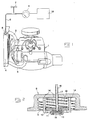
- a conventional combustion engine with an engine block 1 is illustrated. Inside the block there are cylinders with pistons which are movable in the cylinders under influence of forces generated during the combustion of a fuel. Cooling liquid passages which form a part of a cooling system are arranged in the engine block. The cooling liquid passages in the engine block are through conduits 2 and 3 connected to a cooler or radiator 4. During the operation of the motor the cooling liquid will be pumped around in a cycle through the engine block 1, whereas a part of the liquid passes to the radiator 4 in order to be cooled down there and thereafter returned to the engine block 1.
- the invention is based on that the gas leakage from the combustion chamber into the cooling system is measured during the operation of the engine by means of a measuring apparatus 5, which senses pressure and is so connected that it communicates with the interior of the cooling system.
- a measuring apparatus 5 which senses pressure and is so connected that it communicates with the interior of the cooling system.
- the manometer 5 is connectable to the cooling system by means of a conduit 6.
- the measuring apparatus 5 or in this case the conduit 6 is provided with a valve 7 which normally is in closed position but also can be opened in order to attain a connection with the atmosphere.
- the conduit 6 is intended to communicate with the cooling system through a cap means 8, which is intended to substitute the regular cap of the cooling system, in this example its radiator 4, during the testing of the sealing.
- the cap means 8 (fig. 2) is provided with a thread 9 for fastening.
- the cap means has a ring formed seat 10 which at the screwing of the cap onto the radiator is intended to fit up against a ring formed section of the mouth of the radiator in order to attain a sealing connection.
- the cap means 8 has in this example two movable valve means 11, 12, which are intended to open at great pressure differences between the interior of the cooling system and the surrounding atmosphere.
- the valve means 11 is formed like a disc valve and is influenced by a screw compression spring 13 into sealing engagement with a ring formed internal part of the section 10.
- the second valve means 12 is in the example supported by the valve means 11. Also the valve means 12 is formed as a disc valve and is influenced by a compression spring 15 in order to achieve a sealing engagement with the valve means 11. When a negative pressure of a certain size relative to the surrounding atmosphere occurs in the interior of the cooling system as a result of cooling down of the cooling liquid, the valve means 12 can open against the force of the spring 15 in order to allow air flow into the cooling system. Thus, the earlier mentioned overpressure relationship between the interior of the cooling system and the surrounding occurs as a result of a heating-up of the cooling liquid.
- the conduit 6 comprises a section 16, which is rigid and projects freely through an opening 17 in the cap means and is attached to the valve means 12, so that the conduit section can move axially relative to the cap means and follow the valve means 12 in its possible movements.
- Naturally cap means 8 in order to enable an extensive use of the invention, should be provided in different variations so that testing of several vehicle types and brands can be carried out.
- the measuring apparatus 5 in its simplest embodiment could have the character of a simple manometer with a needle index or display panel for direct manual reading, it is naturally within the scope of the invention to form the measuring apparatus 5 as a transductor which transforms the registered pressure values to preferably electrical signals, which are given to a signal processing device 18 for storing and/or presentation of measure data in a manner in itself well known within the techniques of measurement.
- the device can be modified in several ways within the scope of the idea of the invention.
- the cap means 8 is formed for application at the opening of a radiator 4.
- the cap means 8 can just as well be intended to be attached upon the opening of such an expansion vessel.
- the pressure values are used as a criterium of the gas leakage into the cooling system.
- An alternative possibility would be to form the measuring apparatus 5 so that it would measure the volume of the gas flowing out of the cooling system through the conduit 6 during the operation of the engine.
- valve means e. g. the means 11 in the cap means 8
- opening at overpressure in the cooling system should be arranged in order to open at such overpressures which are lying clearly over the generally relatively small overpressures which normally occur during the measuring as a result of gas leakage.
Landscapes
- Engineering & Computer Science (AREA)
- Chemical & Material Sciences (AREA)
- Combustion & Propulsion (AREA)
- Mechanical Engineering (AREA)
- General Engineering & Computer Science (AREA)
- Examining Or Testing Airtightness (AREA)
- Testing Of Engines (AREA)
Priority Applications (1)
| Application Number | Priority Date | Filing Date | Title |
|---|---|---|---|
| AT85900822T ATE35566T1 (de) | 1984-02-21 | 1985-02-04 | Verfahren und vorrichtung zum testen der abdichtung eines verbrennungsmotors. |
Applications Claiming Priority (2)
| Application Number | Priority Date | Filing Date | Title |
|---|---|---|---|
| SE8400930A SE444347B (sv) | 1984-02-21 | 1984-02-21 | Forfarande for tethetsprovning av forbrenningsmotor |
| SE8400930 | 1984-02-21 |
Publications (2)
| Publication Number | Publication Date |
|---|---|
| EP0172844A1 EP0172844A1 (en) | 1986-03-05 |
| EP0172844B1 true EP0172844B1 (en) | 1988-07-06 |
Family
ID=20354830
Family Applications (1)
| Application Number | Title | Priority Date | Filing Date |
|---|---|---|---|
| EP85900822A Expired EP0172844B1 (en) | 1984-02-21 | 1985-02-04 | A method and a device for testing the sealing of a combustion engine |
Country Status (14)
| Country | Link |
|---|---|
| US (1) | US4667507A (it) |
| EP (1) | EP0172844B1 (it) |
| JP (1) | JPS61501282A (it) |
| AU (1) | AU575914B2 (it) |
| BR (1) | BR8505537A (it) |
| CA (1) | CA1245075A (it) |
| DE (1) | DE3563641D1 (it) |
| DK (1) | DK474385A (it) |
| ES (1) | ES8605900A1 (it) |
| FI (1) | FI79887C (it) |
| IT (1) | IT1183200B (it) |
| NO (1) | NO854142L (it) |
| SE (1) | SE444347B (it) |
| WO (1) | WO1985003740A1 (it) |
Families Citing this family (16)
| Publication number | Priority date | Publication date | Assignee | Title |
|---|---|---|---|---|
| DE3623078A1 (de) * | 1986-07-09 | 1988-02-04 | Goetze Ag | Verfahren und vorrichtung zur bestimmung der gasabdichtguete von zylinderkopfdichtungen |
| US4750350A (en) * | 1987-02-17 | 1988-06-14 | Klein Lawrence W | Combustion leak tester |
| US4922999A (en) * | 1989-05-04 | 1990-05-08 | Stokes Bennie J | Radiator with leak detecting and leak-isolating system |
| US5193379A (en) * | 1990-09-27 | 1993-03-16 | Burndy Corporation | Dieless compression head |
| US5105653A (en) * | 1991-02-15 | 1992-04-21 | Konter Richard J | Pressure testing device for vehicle radiators and cooling systems |
| US5324114A (en) * | 1992-01-02 | 1994-06-28 | Waekon Industries, Inc. | Temperature and pressure sensor for cooling systems and other pressurized systems |
| US5633459A (en) * | 1996-02-29 | 1997-05-27 | Rodriguez; Otto M. | Method and apparatus for testing piston rings |
| US5753800A (en) * | 1997-01-16 | 1998-05-19 | Gilliam; Leslie | Smoke generating apparatus for in situ exhaust leak detection |
| WO1999005497A1 (en) * | 1997-07-25 | 1999-02-04 | Bruce Carr | Pressure testing apparatus |
| JP3767875B2 (ja) * | 1997-11-13 | 2006-04-19 | 株式会社小松製作所 | エンジンの異常検出装置および異常検出方法 |
| US7222742B2 (en) * | 2004-09-22 | 2007-05-29 | Wan-Yi Liao | Cap structure for a radiator used in vehicle |
| US7910074B2 (en) * | 2005-10-13 | 2011-03-22 | Beckman Coulter, Inc. | System and method for continuously transferring and processing liquids |
| US7614283B2 (en) * | 2006-04-17 | 2009-11-10 | Lincoln Industrial Corporation | Cooling system testing apparatus and methods |
| US20090301174A1 (en) * | 2008-06-10 | 2009-12-10 | Deming Wen | Cooling system pressure tester |
| KR20130050051A (ko) * | 2011-11-07 | 2013-05-15 | 현대자동차주식회사 | 차량용 냉각 장치 |
| US11306647B1 (en) | 2021-04-28 | 2022-04-19 | Caterpillar Inc. | Combustion gas leak detection strategy |
Citations (3)
| Publication number | Priority date | Publication date | Assignee | Title |
|---|---|---|---|---|
| US2888331A (en) * | 1954-12-27 | 1959-05-26 | Virginia C Carpenter | Testing device |
| US3127246A (en) * | 1964-03-31 | Head gasket leak tester | ||
| US3625656A (en) * | 1969-03-28 | 1971-12-07 | John K Paulson | Gas leak detector for liquid-cooled internal combustion engines |
Family Cites Families (13)
| Publication number | Priority date | Publication date | Assignee | Title |
|---|---|---|---|---|
| US2328289A (en) * | 1940-10-29 | 1943-08-31 | Cities Service Oil Co | Engine leakage meter |
| US2415108A (en) * | 1945-06-15 | 1947-02-04 | Raymond J Newman | Cylinder testing method |
| US3196673A (en) * | 1962-01-05 | 1965-07-27 | Ni Arb Co Inc | Device for testing automotive cooling systems |
| US3255631A (en) * | 1963-01-10 | 1966-06-14 | Du Pont | Temperature indicating apparatus |
| US3266297A (en) * | 1963-12-30 | 1966-08-16 | Henry L Powers | Compression leak tester |
| US3292427A (en) * | 1964-10-12 | 1966-12-20 | Walfred S Mattson | Analysis apparatus |
| US3313144A (en) * | 1965-07-19 | 1967-04-11 | Stant Mfg Company Inc | Radiator overflow tube tester |
| US3608369A (en) * | 1969-11-06 | 1971-09-28 | Herbert O Wilkinson | Engine head test stand |
| US3650147A (en) * | 1970-06-26 | 1972-03-21 | Union Carbide Corp | Cooling system pressure tester |
| US4059985A (en) * | 1976-06-03 | 1977-11-29 | Kelly Buford L | Head gasket leak detector |
| US4102178A (en) * | 1977-03-25 | 1978-07-25 | United Technologies Corporation | Gas in coolant diagnostics for internal combustion engine |
| US4235100A (en) * | 1979-09-13 | 1980-11-25 | Branchini Ricky A | Comprehensive coolant system tester |
| US4494402A (en) * | 1982-09-07 | 1985-01-22 | Carney Patrick T | Device and method for pressure testing |
-
1984
- 1984-02-21 SE SE8400930A patent/SE444347B/sv not_active IP Right Cessation
-
1985
- 1985-02-04 AU AU39311/85A patent/AU575914B2/en not_active Ceased
- 1985-02-04 JP JP60500676A patent/JPS61501282A/ja active Pending
- 1985-02-04 EP EP85900822A patent/EP0172844B1/en not_active Expired
- 1985-02-04 US US06/800,117 patent/US4667507A/en not_active Expired - Fee Related
- 1985-02-04 WO PCT/SE1985/000049 patent/WO1985003740A1/en not_active Ceased
- 1985-02-04 BR BR8505537A patent/BR8505537A/pt unknown
- 1985-02-04 DE DE8585900822T patent/DE3563641D1/de not_active Expired
- 1985-02-14 IT IT19527/85A patent/IT1183200B/it active
- 1985-02-19 CA CA000474679A patent/CA1245075A/en not_active Expired
- 1985-02-20 ES ES540562A patent/ES8605900A1/es not_active Expired
- 1985-10-16 DK DK474385A patent/DK474385A/da not_active Application Discontinuation
- 1985-10-18 NO NO854142A patent/NO854142L/no unknown
- 1985-10-21 FI FI854102A patent/FI79887C/fi not_active IP Right Cessation
Patent Citations (3)
| Publication number | Priority date | Publication date | Assignee | Title |
|---|---|---|---|---|
| US3127246A (en) * | 1964-03-31 | Head gasket leak tester | ||
| US2888331A (en) * | 1954-12-27 | 1959-05-26 | Virginia C Carpenter | Testing device |
| US3625656A (en) * | 1969-03-28 | 1971-12-07 | John K Paulson | Gas leak detector for liquid-cooled internal combustion engines |
Also Published As
| Publication number | Publication date |
|---|---|
| US4667507A (en) | 1987-05-26 |
| DK474385A (da) | 1985-12-10 |
| WO1985003740A1 (en) | 1985-08-29 |
| FI854102A0 (fi) | 1985-10-21 |
| CA1245075A (en) | 1988-11-22 |
| JPS61501282A (ja) | 1986-06-26 |
| DK474385D0 (da) | 1985-10-16 |
| SE8400930L (sv) | 1985-08-22 |
| ES540562A0 (es) | 1986-04-16 |
| IT8519527A0 (it) | 1985-02-14 |
| FI79887B (fi) | 1989-11-30 |
| BR8505537A (pt) | 1986-02-18 |
| SE444347B (sv) | 1986-04-07 |
| EP0172844A1 (en) | 1986-03-05 |
| ES8605900A1 (es) | 1986-04-16 |
| FI854102L (fi) | 1985-10-21 |
| AU3931185A (en) | 1985-09-10 |
| AU575914B2 (en) | 1988-08-11 |
| IT1183200B (it) | 1987-10-05 |
| NO854142L (no) | 1985-10-18 |
| DE3563641D1 (en) | 1988-08-11 |
| SE8400930D0 (sv) | 1984-02-21 |
| FI79887C (fi) | 1990-03-12 |
Similar Documents
| Publication | Publication Date | Title |
|---|---|---|
| EP0172844B1 (en) | A method and a device for testing the sealing of a combustion engine | |
| US4719792A (en) | Method and a device for testing the tightness of an engine | |
| US6276319B2 (en) | Method for evaluating the march of pressure in a combustion chamber | |
| US3924457A (en) | Misfire detecting device for internal combustion engine | |
| JP4509637B2 (ja) | 内燃機関の運転方法および装置 | |
| US5295747A (en) | Temperature and pressure sensor for cooling systems and other pressurized systems | |
| US6314794B1 (en) | Method and apparatus for detecting leaks in heat exchangers for motor vehicles | |
| US5140850A (en) | Process for determining the combustion air mass in the cylinders of an internal combustion engine | |
| US5505079A (en) | Process and device for detecting combustion irregularities in an engine particularly at medium and high speed | |
| US5569841A (en) | Cylinder combustion gas leakage testing | |
| CN110249211B (zh) | 车辆引擎中的燃烧室泄漏检测套件 | |
| US2415108A (en) | Cylinder testing method | |
| KR19990017215A (ko) | 엔진 냉각용 워터 펌프 자동 시험 장치 | |
| US6612155B1 (en) | Testing condition of internal combustion engines by sampled detection of gas leakage | |
| RU2022152C1 (ru) | Способ диагностирования поршневого двигателя внутреннего сгорания | |
| Harrow | Some applications of basic combustion research to gasoline engine development problems | |
| JPH11281531A (ja) | 内燃機関の摩耗量解析装置 | |
| Kunimatsu et al. | Measurement of dynamic pressure using piezoelectric sensors at extremely low temperatures | |
| Witkowski et al. | The impact of a place for the measurement of cylinder pressure of marine piston engine on the indicator diagrams and indicator parameters | |
| JPH04235326A (ja) | 給排気弁異常検知装置 | |
| KR20030027581A (ko) | 차량 엔진의 연소가스 누출 실험시스템 | |
| Paul et al. | A new method of investigating piston ring friction under firing conditions | |
| Diez et al. | Integrated pressure sensor systems in the cylinder-head gasket |
Legal Events
| Date | Code | Title | Description |
|---|---|---|---|
| PUAI | Public reference made under article 153(3) epc to a published international application that has entered the european phase |
Free format text: ORIGINAL CODE: 0009012 |
|
| 17P | Request for examination filed |
Effective date: 19851024 |
|
| AK | Designated contracting states |
Kind code of ref document: A1 Designated state(s): AT BE CH DE FR GB LI LU NL SE |
|
| 17Q | First examination report despatched |
Effective date: 19861007 |
|
| GRAA | (expected) grant |
Free format text: ORIGINAL CODE: 0009210 |
|
| AK | Designated contracting states |
Kind code of ref document: B1 Designated state(s): AT BE CH DE FR GB LI LU NL SE |
|
| PG25 | Lapsed in a contracting state [announced via postgrant information from national office to epo] |
Ref country code: SE Effective date: 19880706 |
|
| REF | Corresponds to: |
Ref document number: 35566 Country of ref document: AT Date of ref document: 19880715 Kind code of ref document: T |
|
| REF | Corresponds to: |
Ref document number: 3563641 Country of ref document: DE Date of ref document: 19880811 |
|
| ET | Fr: translation filed | ||
| PGFP | Annual fee paid to national office [announced via postgrant information from national office to epo] |
Ref country code: FR Payment date: 19890203 Year of fee payment: 5 |
|
| PGFP | Annual fee paid to national office [announced via postgrant information from national office to epo] |
Ref country code: BE Payment date: 19890216 Year of fee payment: 5 |
|
| PGFP | Annual fee paid to national office [announced via postgrant information from national office to epo] |
Ref country code: CH Payment date: 19890217 Year of fee payment: 5 |
|
| PGFP | Annual fee paid to national office [announced via postgrant information from national office to epo] |
Ref country code: AT Payment date: 19890223 Year of fee payment: 5 |
|
| PG25 | Lapsed in a contracting state [announced via postgrant information from national office to epo] |
Ref country code: LU Free format text: LAPSE BECAUSE OF NON-PAYMENT OF DUE FEES Effective date: 19890228 |
|
| PGFP | Annual fee paid to national office [announced via postgrant information from national office to epo] |
Ref country code: NL Payment date: 19890228 Year of fee payment: 5 Ref country code: LU Payment date: 19890228 Year of fee payment: 5 Ref country code: GB Payment date: 19890228 Year of fee payment: 5 |
|
| PGFP | Annual fee paid to national office [announced via postgrant information from national office to epo] |
Ref country code: DE Payment date: 19890425 Year of fee payment: 5 |
|
| PLBE | No opposition filed within time limit |
Free format text: ORIGINAL CODE: 0009261 |
|
| STAA | Information on the status of an ep patent application or granted ep patent |
Free format text: STATUS: NO OPPOSITION FILED WITHIN TIME LIMIT |
|
| 26N | No opposition filed | ||
| PG25 | Lapsed in a contracting state [announced via postgrant information from national office to epo] |
Ref country code: GB Effective date: 19900204 Ref country code: AT Effective date: 19900204 |
|
| PG25 | Lapsed in a contracting state [announced via postgrant information from national office to epo] |
Ref country code: LI Effective date: 19900228 Ref country code: CH Effective date: 19900228 Ref country code: BE Effective date: 19900228 |
|
| BERE | Be: lapsed |
Owner name: ERIKSSON INGEMAR Effective date: 19900228 |
|
| PG25 | Lapsed in a contracting state [announced via postgrant information from national office to epo] |
Ref country code: NL Effective date: 19900901 |
|
| GBPC | Gb: european patent ceased through non-payment of renewal fee | ||
| NLV4 | Nl: lapsed or anulled due to non-payment of the annual fee | ||
| PG25 | Lapsed in a contracting state [announced via postgrant information from national office to epo] |
Ref country code: FR Effective date: 19901031 |
|
| REG | Reference to a national code |
Ref country code: CH Ref legal event code: PL |
|
| PG25 | Lapsed in a contracting state [announced via postgrant information from national office to epo] |
Ref country code: DE Effective date: 19901101 |
|
| REG | Reference to a national code |
Ref country code: FR Ref legal event code: ST |