EP0172801A1 - Ventil mit parallelen Sitzen - Google Patents
Ventil mit parallelen Sitzen Download PDFInfo
- Publication number
- EP0172801A1 EP0172801A1 EP85870106A EP85870106A EP0172801A1 EP 0172801 A1 EP0172801 A1 EP 0172801A1 EP 85870106 A EP85870106 A EP 85870106A EP 85870106 A EP85870106 A EP 85870106A EP 0172801 A1 EP0172801 A1 EP 0172801A1
- Authority
- EP
- European Patent Office
- Prior art keywords
- valve
- shutter
- cover
- seat
- circular grooves
- Prior art date
- Legal status (The legal status is an assumption and is not a legal conclusion. Google has not performed a legal analysis and makes no representation as to the accuracy of the status listed.)
- Withdrawn
Links
- 238000007789 sealing Methods 0.000 claims abstract description 27
- 238000012856 packing Methods 0.000 abstract 1
- 239000007788 liquid Substances 0.000 description 15
- 230000000694 effects Effects 0.000 description 6
- 238000009434 installation Methods 0.000 description 6
- 238000004891 communication Methods 0.000 description 4
- 238000011144 upstream manufacturing Methods 0.000 description 4
- 230000000903 blocking effect Effects 0.000 description 3
- 239000007789 gas Substances 0.000 description 3
- XLYOFNOQVPJJNP-UHFFFAOYSA-N water Substances O XLYOFNOQVPJJNP-UHFFFAOYSA-N 0.000 description 3
- 229910045601 alloy Inorganic materials 0.000 description 2
- 239000000956 alloy Substances 0.000 description 2
- 238000010276 construction Methods 0.000 description 2
- 208000031872 Body Remains Diseases 0.000 description 1
- 241000196324 Embryophyta Species 0.000 description 1
- 229910000831 Steel Inorganic materials 0.000 description 1
- 240000008042 Zea mays Species 0.000 description 1
- 230000006835 compression Effects 0.000 description 1
- 238000007906 compression Methods 0.000 description 1
- 230000001934 delay Effects 0.000 description 1
- 238000006073 displacement reaction Methods 0.000 description 1
- 229940082150 encore Drugs 0.000 description 1
- 239000012530 fluid Substances 0.000 description 1
- 238000009413 insulation Methods 0.000 description 1
- 238000003754 machining Methods 0.000 description 1
- 230000003472 neutralizing effect Effects 0.000 description 1
- 230000002441 reversible effect Effects 0.000 description 1
- 230000035939 shock Effects 0.000 description 1
- 239000010935 stainless steel Substances 0.000 description 1
- 229910001220 stainless steel Inorganic materials 0.000 description 1
- 239000010959 steel Substances 0.000 description 1
- 238000012795 verification Methods 0.000 description 1
- 230000000007 visual effect Effects 0.000 description 1
Images



Classifications
-
- F—MECHANICAL ENGINEERING; LIGHTING; HEATING; WEAPONS; BLASTING
- F16—ENGINEERING ELEMENTS AND UNITS; GENERAL MEASURES FOR PRODUCING AND MAINTAINING EFFECTIVE FUNCTIONING OF MACHINES OR INSTALLATIONS; THERMAL INSULATION IN GENERAL
- F16K—VALVES; TAPS; COCKS; ACTUATING-FLOATS; DEVICES FOR VENTING OR AERATING
- F16K39/00—Devices for relieving the pressure on the sealing faces
- F16K39/04—Devices for relieving the pressure on the sealing faces for sliding valves
-
- F—MECHANICAL ENGINEERING; LIGHTING; HEATING; WEAPONS; BLASTING
- F16—ENGINEERING ELEMENTS AND UNITS; GENERAL MEASURES FOR PRODUCING AND MAINTAINING EFFECTIVE FUNCTIONING OF MACHINES OR INSTALLATIONS; THERMAL INSULATION IN GENERAL
- F16K—VALVES; TAPS; COCKS; ACTUATING-FLOATS; DEVICES FOR VENTING OR AERATING
- F16K3/00—Gate valves or sliding valves, i.e. cut-off apparatus with closing members having a sliding movement along the seat for opening and closing
- F16K3/02—Gate valves or sliding valves, i.e. cut-off apparatus with closing members having a sliding movement along the seat for opening and closing with flat sealing faces; Packings therefor
- F16K3/0227—Packings
- F16K3/0236—Packings the packing being of a non-resilient material, e.g. ceramic, metal
Definitions
- the present invention relates to a valve with parallel seats and free expansion.
- Valves of this type have the advantage of producing only a minute pressure drop. They are mainly used as shutters, because they are very poor adjusting devices. This is about the only type of shutter used - in large dimensions. These valves are used for all fluids, liquids, gases and steam.
- a shutter In a valve of this type, a shutter, controlled by a rod, moves parallel to its contact surfaces.
- This shutter consists of two lids, each being applied against its respective seat by a spring.
- the blocking of the advancement of the shutter control rod between the extreme end positions corresponding to the complete opening or closing may also have another cause, such as for example the presence of a foreign object in the path of the shutter or any other accidental mechanical cause.
- the position of the shutter control rod makes it possible to more reliably determine the opening or closing state of the valve.
- a first solution consists in reducing the annular sealing surface of each seal to a central crown, so as to delay the creation of the overpressure inside the valve body, caused by the descent of the shutter control rod.
- the closing of the liquid passage lights is done only when each seal is almost exactly opposite its seat.
- the reduction in the annular sealing surface results in a reduction in the bearing surface of the cover on its seat, which has the consequence that the cover is subjected to vibrations, the resulting shocks causing the seat to mat.
- the shutter control rod passes right through the valve body.
- the stem volume located inside the valve body remains constant throughout the displacement of the stem.
- the present invention provides a simple, inexpensive and reliable solution to the problem created by the birth of the overpressure in the valve body, by delaying the establishment of perfect sealing. Indeed, this is only achieved when it does the shutter remains more than a few millimeters to travel before reaching its extreme position corresponding to the closing of the valve.
- the subject of the present invention is a valve with parallel seats comprising a circular shutter constituted by two lids with an annular sealing surface on which are attached two seals (10, 11) which constitute the annular sealing surfaces.
- a circular shutter constituted by two lids with an annular sealing surface on which are attached two seals (10, 11) which constitute the annular sealing surfaces.
- On the sealing surface of at least one of the two linings are machined two circular grooves concentric with this sealing surface and connected together by at least one channel.
- the annular sealing surfaces of each of the two linings carry two circular grooves machined concentrically with these surfaces.
- the channel which connects the two circular grooves is advantageously a groove machined radially on the annular sealing surface.
- the two circular grooves are connected by several channels machined radially.
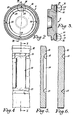
- the valve shown in FIG. 1 consists of a body 1 of steel and a shutter 2 controlled by a rod 3.
- This rod 3 is driven either by a flywheel 4 or by a servomotor.
- the shutter 2 is constituted by two lids 5 and 6 which are applied to their respective seats 7 and 8 by a spring.
- On the lids 5 and 6 are fitted and welded linings 10 and 11 of a hard alloy, which constitute the sealing surfaces of the lids and which come into contact with the parallel seats 7 and 8 also of a hard alloy (see Fig. 1, 2 and 3).
- the linings 10, 11 form annular sealing surfaces, on which are concentrically machined two circular grooves 12 and 13.
- Channels 14 connect these two circular grooves 12 and 13.
- These channels 14 are grooves machined radially on the surfaces of sealing of the linings 10 and 11.
- FIGS. 4 and 5 show in detail the arrangement of a channel 14.
- the circular grooves 12 and 13 as illustrated have a V section (see Fig. 6), but it is obvious that any profile and any depth can be chosen, depending in particular on the machining facilities. It is the same for the channel 14, the depth of which can be less (see Fig. 5), equal to or greater than that of the grooves 12 and 13.
- the communication between the interior of the valve body and the pipes is extended.
- the groove 12 being in communication with the inside of the valve body and the groove 13 being in communication with the pipe, the liquid can circulate through the contact surface between the cover 5 and the seat 7 thanks to the channels 14. The leak thus created delays the establishment of an overpressure in the valve body, when it is closing.
- Figs. 11 and 12 illustrate the cover 5 in its extreme position corresponding to the closing of the valve. Sealing is achieved because both the outer groove 12 and the inner groove 13 are opposite the sealing surface of the seat 7 and are therefore no longer in communication either with the interior of the valve body or with the pipe.
- the invention can also be applied to a valve in which only one latch (5 or 6) is provided grooves 12 and 13 connected by channels 14, the other cover having a planar annular sealing surface.
Landscapes
- Engineering & Computer Science (AREA)
- General Engineering & Computer Science (AREA)
- Mechanical Engineering (AREA)
- Ceramic Engineering (AREA)
- Lift Valve (AREA)
Applications Claiming Priority (2)
| Application Number | Priority Date | Filing Date | Title |
|---|---|---|---|
| FR8412453A FR2568972A1 (fr) | 1984-08-07 | 1984-08-07 | Vanne a sieges paralleles |
| FR8412453 | 1984-08-07 |
Publications (1)
| Publication Number | Publication Date |
|---|---|
| EP0172801A1 true EP0172801A1 (de) | 1986-02-26 |
Family
ID=9306862
Family Applications (1)
| Application Number | Title | Priority Date | Filing Date |
|---|---|---|---|
| EP85870106A Withdrawn EP0172801A1 (de) | 1984-08-07 | 1985-08-07 | Ventil mit parallelen Sitzen |
Country Status (2)
| Country | Link |
|---|---|
| EP (1) | EP0172801A1 (de) |
| FR (1) | FR2568972A1 (de) |
Families Citing this family (1)
| Publication number | Priority date | Publication date | Assignee | Title |
|---|---|---|---|---|
| US20250035219A1 (en) * | 2022-06-28 | 2025-01-30 | Zp Interests, Llc | Pressure energized gate valve seat and seal assembly |
Citations (4)
| Publication number | Priority date | Publication date | Assignee | Title |
|---|---|---|---|---|
| FR1070382A (fr) * | 1953-02-06 | 1954-07-23 | Munzing S A Paris & Montceau L | Dispositif pour soustraire les vannes à deux sièges aux surpressions |
| US3478771A (en) * | 1967-09-15 | 1969-11-18 | Amca Pharm Lab Ltd | Sectional body gate valve with seat scraping means |
| FR2417702A1 (fr) * | 1978-02-17 | 1979-09-14 | Zikesch Gmbh C H | Dispositif de sectionnement, notamment vanne de sectionnement, pour fluides |
| GB2113807A (en) * | 1982-01-27 | 1983-08-10 | Nl Industries Inc | Valve assembly and seat |
-
1984
- 1984-08-07 FR FR8412453A patent/FR2568972A1/fr not_active Withdrawn
-
1985
- 1985-08-07 EP EP85870106A patent/EP0172801A1/de not_active Withdrawn
Patent Citations (4)
| Publication number | Priority date | Publication date | Assignee | Title |
|---|---|---|---|---|
| FR1070382A (fr) * | 1953-02-06 | 1954-07-23 | Munzing S A Paris & Montceau L | Dispositif pour soustraire les vannes à deux sièges aux surpressions |
| US3478771A (en) * | 1967-09-15 | 1969-11-18 | Amca Pharm Lab Ltd | Sectional body gate valve with seat scraping means |
| FR2417702A1 (fr) * | 1978-02-17 | 1979-09-14 | Zikesch Gmbh C H | Dispositif de sectionnement, notamment vanne de sectionnement, pour fluides |
| GB2113807A (en) * | 1982-01-27 | 1983-08-10 | Nl Industries Inc | Valve assembly and seat |
Also Published As
| Publication number | Publication date |
|---|---|
| FR2568972A1 (fr) | 1986-02-14 |
Similar Documents
| Publication | Publication Date | Title |
|---|---|---|
| EP2771598B1 (de) | Isolierventil | |
| EP0165186B1 (de) | Kugelhahn | |
| EP2440806B1 (de) | Stossdämpfer und mit solch einem stossdämpfer versehenes fahrwerk | |
| FR2657138A1 (fr) | Partie de raccord rapide a organe de reduction de pression. | |
| EP3301344B1 (de) | Anschlussvorrichtung, die eine flexible muffe zum sammeln einer flüssigkeit im falle eines lecks oder aussickerns umfasst | |
| WO2015079034A1 (fr) | Robinet d'isolement a chambre morte | |
| EP0396479B1 (de) | Hahn mit Kugelküken | |
| FR2864604A1 (fr) | Raccord et partie d'un tel raccord | |
| CA1261311A (fr) | Dispositif d'obturation pour conduite vehiculant un fluide | |
| FR2512513A1 (fr) | Vanne de commande d'un fluide | |
| FR2727734A1 (fr) | Vannes de reglage a double debit | |
| EP0268521B1 (de) | Schleusenventil | |
| EP0239451A1 (de) | Rückschlagventil, insbesondere für Druckwasserreaktor | |
| FR2516195A1 (fr) | Obturateur pour robinet melangeur commande par levier unique | |
| EP0579519B1 (de) | Servogesteuertes Ventil | |
| FR2564935A1 (fr) | Soupape de retenue pour fluides liquides ou aeriformes | |
| FR2617562A1 (fr) | Ensemble de vanne a clapet | |
| FR2568972A1 (fr) | Vanne a sieges paralleles | |
| FR2594520A1 (fr) | Joint de bout de tige pour robinet d'arret | |
| FR2609523A1 (fr) | Raccord a obturateur pour circuit de fluide | |
| FR2578952A1 (fr) | Element femelle de raccord a accouplement rapide | |
| WO1994005940A1 (fr) | Vanne du type a siege cylindrique, a siege conique ou a tiroir | |
| FR2871212A1 (fr) | Dispositifs de fermeture et d'etancheite par tube a moyen immerge et profil d'ecoulement optimise | |
| FR2473671A1 (fr) | Vanne a bille demontable | |
| EP2811208A1 (de) | Absperr- und Regulierhahn |
Legal Events
| Date | Code | Title | Description |
|---|---|---|---|
| PUAI | Public reference made under article 153(3) epc to a published international application that has entered the european phase |
Free format text: ORIGINAL CODE: 0009012 |
|
| 17P | Request for examination filed |
Effective date: 19850925 |
|
| AK | Designated contracting states |
Designated state(s): AT BE CH DE GB IT LI LU NL SE |
|
| 17Q | First examination report despatched |
Effective date: 19860910 |
|
| STAA | Information on the status of an ep patent application or granted ep patent |
Free format text: STATUS: THE APPLICATION IS DEEMED TO BE WITHDRAWN |
|
| 18D | Application deemed to be withdrawn |
Effective date: 19870121 |
|
| RIN1 | Information on inventor provided before grant (corrected) |
Inventor name: L'INVENTEUR A RENONCE A SA DESIGNATION. |