EP0172002A2 - Traitement des pistons - Google Patents
Traitement des pistons Download PDFInfo
- Publication number
- EP0172002A2 EP0172002A2 EP85305651A EP85305651A EP0172002A2 EP 0172002 A2 EP0172002 A2 EP 0172002A2 EP 85305651 A EP85305651 A EP 85305651A EP 85305651 A EP85305651 A EP 85305651A EP 0172002 A2 EP0172002 A2 EP 0172002A2
- Authority
- EP
- European Patent Office
- Prior art keywords
- crown
- detonation
- piston
- edge
- ring band
- Prior art date
- Legal status (The legal status is an assumption and is not a legal conclusion. Google has not performed a legal analysis and makes no representation as to the accuracy of the status listed.)
- Withdrawn
Links
- 239000000463 material Substances 0.000 claims abstract description 39
- 238000005474 detonation Methods 0.000 claims abstract description 36
- PXHVJJICTQNCMI-UHFFFAOYSA-N Nickel Chemical compound [Ni] PXHVJJICTQNCMI-UHFFFAOYSA-N 0.000 claims abstract description 34
- 238000000034 method Methods 0.000 claims abstract description 19
- 229910052759 nickel Inorganic materials 0.000 claims abstract description 14
- 238000007747 plating Methods 0.000 claims abstract description 10
- 238000000576 coating method Methods 0.000 claims description 15
- 239000011248 coating agent Substances 0.000 claims description 14
- 229910000838 Al alloy Inorganic materials 0.000 claims description 8
- 229910000990 Ni alloy Inorganic materials 0.000 claims description 6
- XAGFODPZIPBFFR-UHFFFAOYSA-N aluminium Chemical compound [Al] XAGFODPZIPBFFR-UHFFFAOYSA-N 0.000 claims description 6
- 239000004411 aluminium Substances 0.000 claims description 5
- 229910052782 aluminium Inorganic materials 0.000 claims description 5
- 239000010941 cobalt Substances 0.000 claims description 4
- 229910017052 cobalt Inorganic materials 0.000 claims description 4
- GUTLYIVDDKVIGB-UHFFFAOYSA-N cobalt atom Chemical compound [Co] GUTLYIVDDKVIGB-UHFFFAOYSA-N 0.000 claims description 4
- 238000002485 combustion reaction Methods 0.000 claims description 4
- 229910000640 Fe alloy Inorganic materials 0.000 claims description 3
- ATJFFYVFTNAWJD-UHFFFAOYSA-N Tin Chemical compound [Sn] ATJFFYVFTNAWJD-UHFFFAOYSA-N 0.000 claims description 3
- 238000009713 electroplating Methods 0.000 claims description 3
- WFKWXMTUELFFGS-UHFFFAOYSA-N tungsten Chemical compound [W] WFKWXMTUELFFGS-UHFFFAOYSA-N 0.000 claims description 3
- 229910052721 tungsten Inorganic materials 0.000 claims description 3
- 239000010937 tungsten Substances 0.000 claims description 3
- ZOKXTWBITQBERF-UHFFFAOYSA-N Molybdenum Chemical compound [Mo] ZOKXTWBITQBERF-UHFFFAOYSA-N 0.000 claims description 2
- UFGZSIPAQKLCGR-UHFFFAOYSA-N chromium carbide Chemical compound [Cr]#C[Cr]C#[Cr] UFGZSIPAQKLCGR-UHFFFAOYSA-N 0.000 claims description 2
- 239000002131 composite material Substances 0.000 claims description 2
- 239000003792 electrolyte Substances 0.000 claims description 2
- 239000000203 mixture Substances 0.000 claims description 2
- 229910052750 molybdenum Inorganic materials 0.000 claims description 2
- 239000011733 molybdenum Substances 0.000 claims description 2
- 229910003470 tongbaite Inorganic materials 0.000 claims description 2
- 229910000531 Co alloy Inorganic materials 0.000 claims 2
- 229910001128 Sn alloy Inorganic materials 0.000 claims 2
- UPHIPHFJVNKLMR-UHFFFAOYSA-N chromium iron Chemical compound [Cr].[Fe] UPHIPHFJVNKLMR-UHFFFAOYSA-N 0.000 claims 1
- 238000007790 scraping Methods 0.000 abstract 1
- XEEYBQQBJWHFJM-UHFFFAOYSA-N Iron Chemical compound [Fe] XEEYBQQBJWHFJM-UHFFFAOYSA-N 0.000 description 8
- 239000000446 fuel Substances 0.000 description 4
- 230000006835 compression Effects 0.000 description 3
- 238000007906 compression Methods 0.000 description 3
- VYZAMTAEIAYCRO-UHFFFAOYSA-N Chromium Chemical compound [Cr] VYZAMTAEIAYCRO-UHFFFAOYSA-N 0.000 description 2
- 229910052804 chromium Inorganic materials 0.000 description 2
- 239000011651 chromium Substances 0.000 description 2
- 238000007772 electroless plating Methods 0.000 description 2
- 229910052742 iron Inorganic materials 0.000 description 2
- OKTJSMMVPCPJKN-UHFFFAOYSA-N Carbon Chemical compound [C] OKTJSMMVPCPJKN-UHFFFAOYSA-N 0.000 description 1
- 229920000742 Cotton Polymers 0.000 description 1
- 241001125877 Gobio gobio Species 0.000 description 1
- 229910000826 Lo-Ex Inorganic materials 0.000 description 1
- 238000005299 abrasion Methods 0.000 description 1
- 239000000567 combustion gas Substances 0.000 description 1
- 239000007789 gas Substances 0.000 description 1
- 229910002804 graphite Inorganic materials 0.000 description 1
- 239000010439 graphite Substances 0.000 description 1
- 239000000314 lubricant Substances 0.000 description 1
- 230000000873 masking effect Effects 0.000 description 1
- 230000010355 oscillation Effects 0.000 description 1
- 239000002245 particle Substances 0.000 description 1
- 238000007750 plasma spraying Methods 0.000 description 1
- 239000011148 porous material Substances 0.000 description 1
- 238000007789 sealing Methods 0.000 description 1
- HBMJWWWQQXIZIP-UHFFFAOYSA-N silicon carbide Chemical compound [Si+]#[C-] HBMJWWWQQXIZIP-UHFFFAOYSA-N 0.000 description 1
- 229910010271 silicon carbide Inorganic materials 0.000 description 1
- 230000007704 transition Effects 0.000 description 1
- MTPVUVINMAGMJL-UHFFFAOYSA-N trimethyl(1,1,2,2,2-pentafluoroethyl)silane Chemical compound C[Si](C)(C)C(F)(F)C(F)(F)F MTPVUVINMAGMJL-UHFFFAOYSA-N 0.000 description 1
- UONOETXJSWQNOL-UHFFFAOYSA-N tungsten carbide Chemical compound [W+]#[C-] UONOETXJSWQNOL-UHFFFAOYSA-N 0.000 description 1
Images
Classifications
-
- F—MECHANICAL ENGINEERING; LIGHTING; HEATING; WEAPONS; BLASTING
- F16—ENGINEERING ELEMENTS AND UNITS; GENERAL MEASURES FOR PRODUCING AND MAINTAINING EFFECTIVE FUNCTIONING OF MACHINES OR INSTALLATIONS; THERMAL INSULATION IN GENERAL
- F16J—PISTONS; CYLINDERS; SEALINGS
- F16J1/00—Pistons; Trunk pistons; Plungers
- F16J1/001—One-piece pistons
-
- B—PERFORMING OPERATIONS; TRANSPORTING
- B23—MACHINE TOOLS; METAL-WORKING NOT OTHERWISE PROVIDED FOR
- B23P—METAL-WORKING NOT OTHERWISE PROVIDED FOR; COMBINED OPERATIONS; UNIVERSAL MACHINE TOOLS
- B23P15/00—Making specific metal objects by operations not covered by a single other subclass or a group in this subclass
- B23P15/10—Making specific metal objects by operations not covered by a single other subclass or a group in this subclass pistons
-
- F—MECHANICAL ENGINEERING; LIGHTING; HEATING; WEAPONS; BLASTING
- F02—COMBUSTION ENGINES; HOT-GAS OR COMBUSTION-PRODUCT ENGINE PLANTS
- F02F—CYLINDERS, PISTONS OR CASINGS, FOR COMBUSTION ENGINES; ARRANGEMENTS OF SEALINGS IN COMBUSTION ENGINES
- F02F3/00—Pistons
- F02F3/10—Pistons having surface coverings
- F02F3/12—Pistons having surface coverings on piston heads
-
- F—MECHANICAL ENGINEERING; LIGHTING; HEATING; WEAPONS; BLASTING
- F02—COMBUSTION ENGINES; HOT-GAS OR COMBUSTION-PRODUCT ENGINE PLANTS
- F02F—CYLINDERS, PISTONS OR CASINGS, FOR COMBUSTION ENGINES; ARRANGEMENTS OF SEALINGS IN COMBUSTION ENGINES
- F02F2200/00—Manufacturing
- F02F2200/04—Forging of engine parts
-
- F—MECHANICAL ENGINEERING; LIGHTING; HEATING; WEAPONS; BLASTING
- F05—INDEXING SCHEMES RELATING TO ENGINES OR PUMPS IN VARIOUS SUBCLASSES OF CLASSES F01-F04
- F05C—INDEXING SCHEME RELATING TO MATERIALS, MATERIAL PROPERTIES OR MATERIAL CHARACTERISTICS FOR MACHINES, ENGINES OR PUMPS OTHER THAN NON-POSITIVE-DISPLACEMENT MACHINES OR ENGINES
- F05C2201/00—Metals
- F05C2201/02—Light metals
- F05C2201/021—Aluminium
-
- F—MECHANICAL ENGINEERING; LIGHTING; HEATING; WEAPONS; BLASTING
- F05—INDEXING SCHEMES RELATING TO ENGINES OR PUMPS IN VARIOUS SUBCLASSES OF CLASSES F01-F04
- F05C—INDEXING SCHEME RELATING TO MATERIALS, MATERIAL PROPERTIES OR MATERIAL CHARACTERISTICS FOR MACHINES, ENGINES OR PUMPS OTHER THAN NON-POSITIVE-DISPLACEMENT MACHINES OR ENGINES
- F05C2201/00—Metals
- F05C2201/04—Heavy metals
- F05C2201/0403—Refractory metals, e.g. V, W
-
- F—MECHANICAL ENGINEERING; LIGHTING; HEATING; WEAPONS; BLASTING
- F05—INDEXING SCHEMES RELATING TO ENGINES OR PUMPS IN VARIOUS SUBCLASSES OF CLASSES F01-F04
- F05C—INDEXING SCHEME RELATING TO MATERIALS, MATERIAL PROPERTIES OR MATERIAL CHARACTERISTICS FOR MACHINES, ENGINES OR PUMPS OTHER THAN NON-POSITIVE-DISPLACEMENT MACHINES OR ENGINES
- F05C2201/00—Metals
- F05C2201/04—Heavy metals
- F05C2201/0433—Iron group; Ferrous alloys, e.g. steel
- F05C2201/0466—Nickel
-
- F—MECHANICAL ENGINEERING; LIGHTING; HEATING; WEAPONS; BLASTING
- F05—INDEXING SCHEMES RELATING TO ENGINES OR PUMPS IN VARIOUS SUBCLASSES OF CLASSES F01-F04
- F05C—INDEXING SCHEME RELATING TO MATERIALS, MATERIAL PROPERTIES OR MATERIAL CHARACTERISTICS FOR MACHINES, ENGINES OR PUMPS OTHER THAN NON-POSITIVE-DISPLACEMENT MACHINES OR ENGINES
- F05C2203/00—Non-metallic inorganic materials
- F05C2203/08—Ceramics; Oxides
- F05C2203/0865—Oxide ceramics
- F05C2203/0882—Carbon, e.g. graphite
-
- Y—GENERAL TAGGING OF NEW TECHNOLOGICAL DEVELOPMENTS; GENERAL TAGGING OF CROSS-SECTIONAL TECHNOLOGIES SPANNING OVER SEVERAL SECTIONS OF THE IPC; TECHNICAL SUBJECTS COVERED BY FORMER USPC CROSS-REFERENCE ART COLLECTIONS [XRACs] AND DIGESTS
- Y10—TECHNICAL SUBJECTS COVERED BY FORMER USPC
- Y10T—TECHNICAL SUBJECTS COVERED BY FORMER US CLASSIFICATION
- Y10T29/00—Metal working
- Y10T29/49—Method of mechanical manufacture
- Y10T29/49229—Prime mover or fluid pump making
- Y10T29/49249—Piston making
- Y10T29/49256—Piston making with assembly or composite article making
- Y10T29/49263—Piston making with assembly or composite article making by coating or cladding
-
- Y—GENERAL TAGGING OF NEW TECHNOLOGICAL DEVELOPMENTS; GENERAL TAGGING OF CROSS-SECTIONAL TECHNOLOGIES SPANNING OVER SEVERAL SECTIONS OF THE IPC; TECHNICAL SUBJECTS COVERED BY FORMER USPC CROSS-REFERENCE ART COLLECTIONS [XRACs] AND DIGESTS
- Y10—TECHNICAL SUBJECTS COVERED BY FORMER USPC
- Y10T—TECHNICAL SUBJECTS COVERED BY FORMER US CLASSIFICATION
- Y10T29/00—Metal working
- Y10T29/49—Method of mechanical manufacture
- Y10T29/49826—Assembling or joining
- Y10T29/49885—Assembling or joining with coating before or during assembling
Definitions
- the invention relates to a method of treating a piston of aluminium or aluminium alloy and of the kind comprising a crown and a ring band extending around the crown and meeting the crown at an edge therebetween.
- a conventional piston comprises a crown and a ring band, extending around the crown and meeting the crown at an edge.
- One or more piston ring grooves are formed in the ring band and carry respective rings; the uppermost of which is a compression ring sealing against an associated cylinder or liner to prevent the downward passage of high pressure gases from the combustion of a fuel/air mixture above the crown.
- the detonation of fuel can cause damage to the piston, particularly to those portions of the crown and the ring band adjacent the edge between them. This is an increasing problem, since in recent years engine designers have tended to design engines which operate with higher air/fuel ratios. In addition, less and less lead is being used in fuels. Both of these measures produce an increased tendency for an engine to 'pink' or 'knock' which, in turn, leads to an increased likelihood of detonation damage.
- a piston oscillates in the associated cylinder or liner and also tends to pivot about a gudgeon pin, by which the piston is connected to an associated connecting rod.
- a gudgeon pin by which the piston is connected to an associated connecting rod.
- the upper part of the ring band adjacent the edge between the ring band and the crown to touch the associated cylinder or liner.
- the presence of a coating, such as nickel, in this region can lead to scoring or scuffing on the associated cylinder or liner, and this is plainly undesirable. Under certain conditions, it is even possible for the coating to be scraped-off the piston and particles of coating in the lubricant are another source of unwanted scoring or scuffing.
- a method of treating a piston of aluminum or aluminium alloy and of the kind comprising a crown and a ring band extending around the crown and meeting the crown at an edge therebetween, characterised in that the surface of the ring band is cut away at said edge, and then said cut-away portion is treated to provide in said cut-away portion, a material which has improved resistance to detonation in comparison with the material of the piston, said detonation- resistant material in the cut-away portion having a thickness at any point not greater than the depth of the recess at that point.
- the detonation-resistant material on the part of the ring band adjacent the edge of the crown is not proud of the surface of the piston but rather is flush or below the surrounding piston surface. This reduces substantially the likelihood of the coating scoring or scuffing the associated cylinder or liner and also reduces the likelihood of the coating being damaged and removed.
- a piston when made by the method of the first aspect of the invention.
- a piston for an internal combustion engine and of aluminium or an aluminium alloy comprising a crown and a ring band extending around the crown and meeting the crown at an edge, characterised in that the ring band is provided with a cut-away portion extending around the ring band from said edge, the cut-away portion having thereon a material which has improved resistance to detonation in comparison with the material of the piston, the detonation-resistant material not extending beyond the depth of the cut-away portion.
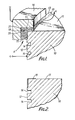
- the piston 10 is forged or cast, preferably squeeze cast from a suitable aluminium or aluminium alloy, such as that known by the trade name Lo-Ex.
- the piston has a crown 11, and a ring band 12 extending around the crown and meeting at an annular edge 13.
- the ring band is formed with one or more piston ring grooves 14; only two are shown in Figure 1.
- the uppermost piston ring groove is for accommodating a compression ring (not shown) which acts to prevent combustion gases passing between the piston and the associated cylinder.
- the piston is treated in the following way to reduce the incidence of detonation damage.
- First an annular recess 15 is machined around the ring band, extending downwardly from the edge between the ring band 12 and the crown 11 almost to the uppermost piston ring groove 14.
- the depth of the recess is approximately 0.025 mm but any other suitable depth may be used.
- the recess 15 extends almost down to the uppermost piston ring groove.
- the recessed piston 10 is next mounted in an apparatus for treating the piston, to apply to the recesses a detonation-resistant coating.
- the apparatus comprises a mounting for the piston 10 (not shown) which allows the piston 10 to be rotated about its axis during treatment.
- an annular anode 16 which may be of graphite.
- the anode 16 is arranged coaxially with the axis of the piston 10 and is formed with a step of inverted L -shape providing annular radially extending and axially extending surfaces 17, 18 respectively.
- the radial surface 17 is spaced axially from the crown 11 of the piston and overlaps an annular portion 19 of the piston extending radially inwardly from the edge 13.
- the axially extending surface is radially spaced from and parallel to the recess 15.
- a porous pad 21 is placed in this gap 20 and is of any suitable porous material such as the material sold under the trade name SCOTCHBRITE or an absorbent cotton or a woven or non-woven material.
- the porous pad 21 contains a suitable electrolyte of the material which is to be plated.
- a plating solution is pumped through the gap 20 as shown by the arrows A in Figure 1.
- plating materials of which the following are examples. They can be used either alone or in combination.
- the examples are as follows: nickel, tin/nickel, tin/cobalt, nickel/iron, nickel/cobalt, composite cobalt/chromium carbide, a chromium/iron/nickel alloy, molybdenum, tungsten, tungsten carbide.
- the electrolytic plating process is continued for a time sufficient to plate the recess 15 and the crown portion 19 with a thickness of plating material not greater than the depth of the recess 15. It will be appreciated that a suitable masking material may be used as necessary. Preferably, the thickness of the plating is just less than the depth of the recess at any point. This is shown in Figure 2.
- the coating may be a graded multi-layer coating using any required combination of the materials referred to above.
- the materials referred to above there may be provided successive coatings of nickel and chromium/iron or chomium/iron/nickel alloy or nickel and silicon carbide followed by nickel and titanium carbide.
- the plating may be electroless plating or a plasma spraying technique.
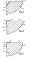
- the piston is prepared in any one of the ways described above with reference to Figure 1, except that the recess 15 is omitted. Rather, in this embodiment, the ring band 12 and the crown 11 are cut-away around the piston to form a bevelled surface 23 extending around the piston.
- This is provided with a detonation-resistant coating in any of the ways described above with reference to the drawings, but with the anode 16 and the associated parts shaped appropriately in order to provided a detonation-resistant coating 24 on the surface 23.
- the recess 15 is shaped generally as described above with reference to Figures 1 and 2, parts common to these Figures and to Figure 4 being given the same reference numerals and not being specifically described.
- a radiussed edge 25 is provided between the recess 15 and the crown portion 19 to provide a smooth transition between those surfaces for the plating, which is applied in any one of the ways described above with reference to Figures 1 and 2.
- this embodiment is generally similar to the embodiment of Figure 4 and parts common to the two Figures are given the same reference numerals and are not specifically described.
- the lower end of the recess 15 is provided with an annular radially inwardly extending relief 26. This prevents the build-up of plating material at this lower edge - the plating being applied in any one of the ways described above with reference to Figures 1 and 2.
- the detonation-resistant material is unaffected by pivoting and oscillation of the piston in an associated cylinder because there is no projecting part of the coating to engage and damage the associated cylinder or liner. This also reduces the tendency of the detonation resistant material to be removed from the piston and so reduces the likelihood of abrasion or scuffing caused in this way.
- the presence of the detonation-resistant material in this region reduces the tendency for detonation to occur and, since this is the region where detonation is most likely, the material thus reduces the incidence of detonation.
- test conditions are as follows:-
Landscapes
- Engineering & Computer Science (AREA)
- General Engineering & Computer Science (AREA)
- Mechanical Engineering (AREA)
- Chemical & Material Sciences (AREA)
- Combustion & Propulsion (AREA)
- Pistons, Piston Rings, And Cylinders (AREA)
- Electroplating Methods And Accessories (AREA)
Applications Claiming Priority (4)
| Application Number | Priority Date | Filing Date | Title |
|---|---|---|---|
| GB848420544A GB8420544D0 (en) | 1984-08-13 | 1984-08-13 | Treatment of pistons |
| GB8420544 | 1984-08-13 | ||
| GB848422672A GB8422672D0 (en) | 1984-09-07 | 1984-09-07 | Treatment of pistons |
| GB8422672 | 1984-09-07 |
Publications (2)
| Publication Number | Publication Date |
|---|---|
| EP0172002A2 true EP0172002A2 (fr) | 1986-02-19 |
| EP0172002A3 EP0172002A3 (fr) | 1986-12-30 |
Family
ID=26288112
Family Applications (1)
| Application Number | Title | Priority Date | Filing Date |
|---|---|---|---|
| EP85305651A Withdrawn EP0172002A3 (fr) | 1984-08-13 | 1985-08-08 | Traitement des pistons |
Country Status (3)
| Country | Link |
|---|---|
| US (1) | US4664021A (fr) |
| EP (1) | EP0172002A3 (fr) |
| GB (1) | GB2163073B (fr) |
Cited By (1)
| Publication number | Priority date | Publication date | Assignee | Title |
|---|---|---|---|---|
| FR2603661A1 (fr) * | 1986-09-09 | 1988-03-11 | Renault | Procede de renforcement de la surface d'un piston de moteur a explosion et piston ainsi obtenu |
Families Citing this family (10)
| Publication number | Priority date | Publication date | Assignee | Title |
|---|---|---|---|---|
| US5435873A (en) * | 1991-11-01 | 1995-07-25 | Decc Technology Partnership, A Limited Partnership Of Which The Decc Company, Inc. Is A General Partner | Method and apparatus for sizing a piston |
| US5266142A (en) * | 1991-11-01 | 1993-11-30 | Decc Technology Partnership A Limited Partnership | Coated piston and method and apparatus of coating the same |
| US5435872A (en) * | 1991-11-01 | 1995-07-25 | Decc Technology Partnership | Sized coated pistons |
| CA2107866A1 (fr) * | 1992-10-13 | 1994-04-14 | Sue Troup-Packman | Pieces en alliage d'aluminium recouvertes d'une couche de fer et methode de realisation de la couche de fer |
| US5450784A (en) * | 1993-09-28 | 1995-09-19 | Detroit Diesel Corporation | Electroplated piston skirt for improved scuff resistance |
| US5469777A (en) * | 1994-07-05 | 1995-11-28 | Ford Motor Company | Piston assembly having abradable coating |
| US6282898B1 (en) * | 1999-05-13 | 2001-09-04 | Alberto Solaroli | Operation of forced induction internal combustion engines |
| US8057644B2 (en) * | 2005-07-26 | 2011-11-15 | Federal-Mogul World Wide, Inc. | Process and apparatus for plating articles |
| FR2932897B1 (fr) | 2008-06-20 | 2010-07-30 | Europ De Systemes Optiques Soc | Procede de faconnage d'un element optique aspherique |
| CN112805463B (zh) * | 2018-10-08 | 2023-10-31 | 辉门汽车零部件有限责任公司 | 抗爆活塞 |
Family Cites Families (16)
| Publication number | Priority date | Publication date | Assignee | Title |
|---|---|---|---|---|
| US1256954A (en) * | 1915-06-08 | 1918-02-19 | William Joseph Travers | Process of metal-plating aluminium. |
| US1467255A (en) * | 1922-04-17 | 1923-09-04 | Thomson John | Engine piston |
| CH227662A (de) * | 1938-05-03 | 1943-06-30 | Berghaus Bernhard | Mit Metallschutzschicht versehener Leichtmetallkolben für Verbrennungskraftmaschinen, sowie Verfahren und Vorrichtung zur Herstellung von Metallschutzschichten an Leichtmetallkolben. |
| US2323074A (en) * | 1940-08-29 | 1943-06-29 | Neugebauer Franz | Piston head |
| US2403455A (en) * | 1945-04-09 | 1946-07-09 | Hastings Mfg Co | Piston |
| FR1045745A (fr) * | 1951-05-31 | 1953-12-01 | Mahle Kg | Moteur à combustion interne avec cylindres et pistons en métal léger |
| US3203321A (en) * | 1955-02-01 | 1965-08-31 | Darlite Corp | Article of bonded ferrous metal and aluminum |
| US2992869A (en) * | 1957-04-15 | 1961-07-18 | Horst Corp Of America V D | Engine piston |
| US3075817A (en) * | 1961-02-28 | 1963-01-29 | Harvey Aluminum Inc | Reinforced light weight piston |
| US3358349A (en) * | 1964-08-05 | 1967-12-19 | Darlite Corp | Method of explosion cladding irregular aluminum objects |
| GB1146835A (en) * | 1965-07-14 | 1969-03-26 | Wellworthy Ltd | Improvements in or relating to pistons |
| FR1460183A (fr) * | 1965-11-18 | 1966-11-25 | Piston | |
| GB1326480A (en) * | 1971-12-31 | 1973-08-15 | Trw Inc | Piston ring grooves |
| US3911891A (en) * | 1973-08-13 | 1975-10-14 | Robert D Dowell | Coating for metal surfaces and method for application |
| DE2639294C2 (de) * | 1976-09-01 | 1982-05-13 | Mahle Gmbh, 7000 Stuttgart | Gepreßter Aluminiumkolben für Verbrennungsmotoren mit Einlagen aus einem anderen Werkstoff |
| DE3201498A1 (de) * | 1982-01-20 | 1983-07-28 | Karl Schmidt Gmbh, 7107 Neckarsulm | Leichtmetallkolben |
-
1985
- 1985-08-08 EP EP85305651A patent/EP0172002A3/fr not_active Withdrawn
- 1985-08-08 GB GB08519969A patent/GB2163073B/en not_active Expired
- 1985-08-12 US US06/764,573 patent/US4664021A/en not_active Expired - Fee Related
Cited By (1)
| Publication number | Priority date | Publication date | Assignee | Title |
|---|---|---|---|---|
| FR2603661A1 (fr) * | 1986-09-09 | 1988-03-11 | Renault | Procede de renforcement de la surface d'un piston de moteur a explosion et piston ainsi obtenu |
Also Published As
| Publication number | Publication date |
|---|---|
| EP0172002A3 (fr) | 1986-12-30 |
| GB2163073B (en) | 1988-03-02 |
| GB2163073A (en) | 1986-02-19 |
| GB8519969D0 (en) | 1985-09-18 |
| US4664021A (en) | 1987-05-12 |
Similar Documents
| Publication | Publication Date | Title |
|---|---|---|
| US4679493A (en) | Reinforced pistons | |
| JP2911003B2 (ja) | エンジン用スリーブ | |
| EP0172002A2 (fr) | Traitement des pistons | |
| US6817333B2 (en) | Piston and cylinder bore having improved scuffing resistance | |
| EP2655940B1 (fr) | Segment de piston pour piston de moteur à combustion interne et son procédé de production | |
| KR950000917B1 (ko) | 피스톤 | |
| DE69523215T2 (de) | Zylinder-Einheit und Verfahren zum Herstellen von Laufflächen | |
| US4570946A (en) | Nitrided piston ring with outer layer on surface | |
| US4592964A (en) | Wear-resistant coating | |
| US3095204A (en) | Wear-resistant lining for piston-ring groove | |
| EP0719917B1 (fr) | Unité cylindre et procédé pour former les surfaces glissières | |
| US4955353A (en) | Piston for internal combustion engine | |
| GB2153965A (en) | Nitrided steel crack resistant piston ring | |
| KR100636712B1 (ko) | 고착된 미끄럼 베어링 층을 구비한 커넥팅 로드 제조 방법 | |
| KR100444566B1 (ko) | 미끄럼 부재 | |
| KR100622958B1 (ko) | 베어링 메탈을 구비한 커넥팅 로드 | |
| KR20010014176A (ko) | 복합 베어링을 구비한 커넥팅 로드 | |
| JPS61118546A (ja) | アルミニウムまたはアルミニウム合金より成るピストン上に耐爆轟性被覆を施こす方法 | |
| JP2709613B2 (ja) | ピストンリング | |
| JPH0681711A (ja) | 内燃機関用ピストン | |
| GB2158185A (en) | Reinforced light metal pistons | |
| EP4332414B1 (fr) | Segment de piston | |
| US3913199A (en) | Ring manufacture, productive of face contact seal | |
| JPS62282150A (ja) | ピストンリングとシリンダの組合せ | |
| CN220726439U (zh) | 一种汽缸缸孔底部倒角结构 |
Legal Events
| Date | Code | Title | Description |
|---|---|---|---|
| PUAI | Public reference made under article 153(3) epc to a published international application that has entered the european phase |
Free format text: ORIGINAL CODE: 0009012 |
|
| AK | Designated contracting states |
Designated state(s): DE FR IT |
|
| 17P | Request for examination filed |
Effective date: 19860217 |
|
| PUAL | Search report despatched |
Free format text: ORIGINAL CODE: 0009013 |
|
| AK | Designated contracting states |
Kind code of ref document: A3 Designated state(s): DE FR IT |
|
| 17Q | First examination report despatched |
Effective date: 19881209 |
|
| STAA | Information on the status of an ep patent application or granted ep patent |
Free format text: STATUS: THE APPLICATION IS DEEMED TO BE WITHDRAWN |
|
| 18D | Application deemed to be withdrawn |
Effective date: 19910302 |
|
| RIN1 | Information on inventor provided before grant (corrected) |
Inventor name: RUDDY, BRIAN LEONARD |