EP0171996B1 - Flache Formkörper mit mindestens zwei Schichten - Google Patents
Flache Formkörper mit mindestens zwei Schichten Download PDFInfo
- Publication number
- EP0171996B1 EP0171996B1 EP85305624A EP85305624A EP0171996B1 EP 0171996 B1 EP0171996 B1 EP 0171996B1 EP 85305624 A EP85305624 A EP 85305624A EP 85305624 A EP85305624 A EP 85305624A EP 0171996 B1 EP0171996 B1 EP 0171996B1
- Authority
- EP
- European Patent Office
- Prior art keywords
- strip
- layers
- rolls
- layer
- nip
- Prior art date
- Legal status (The legal status is an assumption and is not a legal conclusion. Google has not performed a legal analysis and makes no representation as to the accuracy of the status listed.)
- Expired
Links
- 239000000203 mixture Substances 0.000 claims abstract description 30
- 239000002002 slurry Substances 0.000 claims abstract description 29
- 239000000843 powder Substances 0.000 claims abstract description 27
- 238000005056 compaction Methods 0.000 claims abstract description 22
- 238000000034 method Methods 0.000 claims abstract description 22
- 229920002678 cellulose Polymers 0.000 claims abstract description 12
- 239000001913 cellulose Substances 0.000 claims abstract description 12
- 238000005245 sintering Methods 0.000 claims abstract description 9
- 239000000126 substance Substances 0.000 claims abstract description 9
- 230000000694 effects Effects 0.000 claims abstract description 4
- 239000007769 metal material Substances 0.000 claims description 7
- 239000002245 particle Substances 0.000 claims description 6
- 238000010438 heat treatment Methods 0.000 claims description 5
- 239000000463 material Substances 0.000 abstract description 4
- 239000010410 layer Substances 0.000 description 48
- 229910052751 metal Inorganic materials 0.000 description 27
- 239000002184 metal Substances 0.000 description 27
- 229920000609 methyl cellulose Polymers 0.000 description 9
- 239000001923 methylcellulose Substances 0.000 description 9
- 235000010981 methylcellulose Nutrition 0.000 description 9
- XEEYBQQBJWHFJM-UHFFFAOYSA-N Iron Chemical compound [Fe] XEEYBQQBJWHFJM-UHFFFAOYSA-N 0.000 description 4
- 239000011248 coating agent Substances 0.000 description 4
- 238000000576 coating method Methods 0.000 description 4
- 238000001035 drying Methods 0.000 description 4
- 238000004519 manufacturing process Methods 0.000 description 4
- 230000009467 reduction Effects 0.000 description 4
- 150000002739 metals Chemical class 0.000 description 3
- PXHVJJICTQNCMI-UHFFFAOYSA-N nickel Substances [Ni] PXHVJJICTQNCMI-UHFFFAOYSA-N 0.000 description 3
- 238000005096 rolling process Methods 0.000 description 3
- XLYOFNOQVPJJNP-UHFFFAOYSA-N water Substances O XLYOFNOQVPJJNP-UHFFFAOYSA-N 0.000 description 3
- 229920001479 Hydroxyethyl methyl cellulose Polymers 0.000 description 2
- 229910045601 alloy Inorganic materials 0.000 description 2
- 239000000956 alloy Substances 0.000 description 2
- 230000001680 brushing effect Effects 0.000 description 2
- 238000000151 deposition Methods 0.000 description 2
- LEQAOMBKQFMDFZ-UHFFFAOYSA-N glyoxal Chemical compound O=CC=O LEQAOMBKQFMDFZ-UHFFFAOYSA-N 0.000 description 2
- 239000012535 impurity Substances 0.000 description 2
- 229910052742 iron Inorganic materials 0.000 description 2
- 229910052759 nickel Inorganic materials 0.000 description 2
- VYZAMTAEIAYCRO-UHFFFAOYSA-N Chromium Chemical compound [Cr] VYZAMTAEIAYCRO-UHFFFAOYSA-N 0.000 description 1
- 229910001111 Fine metal Inorganic materials 0.000 description 1
- 239000000654 additive Substances 0.000 description 1
- 230000000996 additive effect Effects 0.000 description 1
- 238000005275 alloying Methods 0.000 description 1
- 239000002518 antifoaming agent Substances 0.000 description 1
- 239000003054 catalyst Substances 0.000 description 1
- 229910052804 chromium Inorganic materials 0.000 description 1
- 239000011651 chromium Substances 0.000 description 1
- 238000004140 cleaning Methods 0.000 description 1
- 238000005097 cold rolling Methods 0.000 description 1
- 238000005260 corrosion Methods 0.000 description 1
- 230000007797 corrosion Effects 0.000 description 1
- 238000007766 curtain coating Methods 0.000 description 1
- 230000008021 deposition Effects 0.000 description 1
- 238000001125 extrusion Methods 0.000 description 1
- 238000005188 flotation Methods 0.000 description 1
- 229940015043 glyoxal Drugs 0.000 description 1
- 238000005098 hot rolling Methods 0.000 description 1
- 239000003112 inhibitor Substances 0.000 description 1
- 239000002923 metal particle Substances 0.000 description 1
- 239000013528 metallic particle Substances 0.000 description 1
- 230000004044 response Effects 0.000 description 1
- 230000006903 response to temperature Effects 0.000 description 1
- 230000000717 retained effect Effects 0.000 description 1
- 239000010935 stainless steel Substances 0.000 description 1
- 229910001220 stainless steel Inorganic materials 0.000 description 1
- 239000002344 surface layer Substances 0.000 description 1
- 238000003466 welding Methods 0.000 description 1
- 239000000080 wetting agent Substances 0.000 description 1
Images
Classifications
-
- B—PERFORMING OPERATIONS; TRANSPORTING
- B22—CASTING; POWDER METALLURGY
- B22F—WORKING METALLIC POWDER; MANUFACTURE OF ARTICLES FROM METALLIC POWDER; MAKING METALLIC POWDER; APPARATUS OR DEVICES SPECIALLY ADAPTED FOR METALLIC POWDER
- B22F5/00—Manufacture of workpieces or articles from metallic powder characterised by the special shape of the product
- B22F5/006—Manufacture of workpieces or articles from metallic powder characterised by the special shape of the product of flat products, e.g. sheets
-
- B—PERFORMING OPERATIONS; TRANSPORTING
- B22—CASTING; POWDER METALLURGY
- B22F—WORKING METALLIC POWDER; MANUFACTURE OF ARTICLES FROM METALLIC POWDER; MAKING METALLIC POWDER; APPARATUS OR DEVICES SPECIALLY ADAPTED FOR METALLIC POWDER
- B22F7/00—Manufacture of composite layers, workpieces, or articles, comprising metallic powder, by sintering the powder, with or without compacting wherein at least one part is obtained by sintering or compression
- B22F7/02—Manufacture of composite layers, workpieces, or articles, comprising metallic powder, by sintering the powder, with or without compacting wherein at least one part is obtained by sintering or compression of composite layers
-
- B—PERFORMING OPERATIONS; TRANSPORTING
- B22—CASTING; POWDER METALLURGY
- B22F—WORKING METALLIC POWDER; MANUFACTURE OF ARTICLES FROM METALLIC POWDER; MAKING METALLIC POWDER; APPARATUS OR DEVICES SPECIALLY ADAPTED FOR METALLIC POWDER
- B22F2998/00—Supplementary information concerning processes or compositions relating to powder metallurgy
- B22F2998/10—Processes characterised by the sequence of their steps
-
- H—ELECTRICITY
- H01—ELECTRIC ELEMENTS
- H01H—ELECTRIC SWITCHES; RELAYS; SELECTORS; EMERGENCY PROTECTIVE DEVICES
- H01H37/00—Thermally-actuated switches
- H01H37/02—Details
- H01H37/32—Thermally-sensitive members
- H01H37/52—Thermally-sensitive members actuated due to deflection of bimetallic element
- H01H2037/525—Details of manufacturing of the bimetals, e.g. connection to non bimetallic elements or insulating coatings
Definitions
- strip flat products
- sheet hereinafter referred to simply as "strip"
- strip flat products
- metallic or non-metallic material of different chemical composition
- the invention has application to bi-metallic or tri-metallic strip intended for use as temperature sensitive elements in thermostats, circuit breakers and the like devices which produce mechanical movement or develop a force in response to temperature change.
- the invention is, however, not limited to such application and is applicable to the production of a wide range of multi-layered strips where the properties of one surface or layer are required to be different from those of other surface(s) and/or layer(s).
- one surface or layer may act as a catalyst or react chemically with another surface or layer when the strip is subjected to specified conditions.
- a process for producing multi-layered strip from metal powder is known from GB-A-2059443 in which self-supporting layers of flexi-strip are roll compacted together in the nip of a compaction mill.
- the process described in GB-A-2059443 has, however, proved to be impracticable due to difficulties in achieving a consistent and satisfactory interfacial contact between superimposed strips and an inability to produce at reasonable cost a satisfactory mechanical bond between the strips.
- the former difficulty arises because of a tendency for one or each strip to move in a direction parallel to the axes of rotation of the compaction rolls.
- the present invention sets out to provide a method of producing strip of at least two layers of metallic and/or non-metallic material of different chemical composition which overcomes the above mentioned disadvantages.
- a method of producing strip comprising at least two material layers of different chemical composition bonded one to another, which method comprises the steps of forming separate slurries of powders of different chemical compositions in film-forming cellulose derivatives, producing from said slurries dried layers in strip form and feeding the dried strip layers in interfacial contact into the nip of a pair of compaction rolls to effect a mechanical bond between the layers, the method being characterised by the step of placing each strip as it passes towards the roll nip in contact with tension control means thereby to impose on each strip a level of back tension sufficient to prevent movement of the respective strip away from a direction generally normal to the rotational axes of the rolls, the controlled imposed level of back tension being additional to that present in each strip due to its weight and disposition.
- One of the strip layers may be subjected to a sintering operation prior to being fed while under tension in interfacial contact with the other strip layer or layers into the nip of the compaction rolls.
- the tension control means may comprise pressure pads, pinch rolls or the like located in advance of the compaction rolls. Alternatively, one or each strip may be passed over and in contact with a stationary surface movable towards and away from the strip path to vary the imposed tension.
- the imposed tension may be varied continuously or intermittently in response to a measured process or strip parameter.
- the strip may comprise layers of metallic material of different chemical composition; alternatively, the layers may be of non-metallic materials or a combination of metallic and non-metallic materials.
- a roughened surface may be produced on one or each surface of one or each strip layer to enhance the mechanical bond between adjacent strip layers. This may be achieved by, for example, lightly brushing the surface(s) of dried compacted layer(s) with a dry or dampened brush or the like. Alternatively, where the powder has magnetic properties, the layer(s) may be passed through a magnetic field prior to drying.
- Improved mechanical bonding between the superimposed strips may be achieved by producing a coarser surface finish to one strip layer, the roughness produced is preferably between 1.27 and 7.62 micrometer (50 and 300 micro inches) roughness average (Ra) value.
- the bonded strip layers may be subjected to one or more additional heat treatments and/or reductions.
- the composition of the metal in any layer may be determined by incorporating into the cellulose derivative powders of different metals with or without any non-metallic additive capable of modifying metal characteristics, the combination of different metals producing the required composition.
- the composition of metal in any layer may be determined by incorporating into the cellulose derivative, metal powder which already is of the composition required and which may be produced by any of conventional means such as alloying. If necessary, the metal composition of any one layer or layers may be produced by a combination of powder of individual metal and alloys.
- each layer is produced by depositing onto a moving support a slurry of the powder or powders and the film forming cellulose derivative and, subsequently, removing each layer from the respective support surface for concurrent compaction under tension within a compaction mill.
- the cellulose derivative is methyl cellulose or methyl hydroxy ethyl cellulose; in this case, an aqueous slurry is deposited upon a moving support which is heated to promote gelling of the methyl cellulose; gelling which occurs at a temperature in excess of about 40°C conveniently is followed by drying to remove water and produces a self supporting film or layer referred to as "flexistrip".
- the flexistrip can be removed from the moving support with relative ease for subsequent compaction.
- the invention provides multi-layered strip produced by one of the methods referred to above.
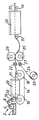
- FIG. 1 a schematic side view of apparatus in accordance with the invention.
- the drawing illustrates apparatus for producing strip comprising two layers of metal of different composition.
- Such strip may comprise bi-metallic strip of well known type conveniently used in the production of thermostats and like heat sensitive devices in which differential expansion of the layer on sensing heat produces mechanical movement.
- Typical bi-metallic strip for such heat sensitive applications have metal compositions in adjacent layers as detailed in Table 1 below; these however are merely examples of a wider range of composition combinations of metallic and non-metallic materials which can be produced by the apparatus of the invention. Typical examples of such compositions are also given in Table 1.
- a slurry 4 is retained in a vessel at a station indicated generally at 2.
- the slurry conveniently is based. upon multiples of 300 g of methyl cellulose treated with glyoxal as a solubility inhibitor together with 12 litres of water optionally containing suitable slurrying and wetting agent.
- Incorporated in the aqueous methyl cellulose is 35 kg of a suitable fine metal powder typically of below 80 B.S. mesh, the particles having a composition by weight of 22% Ni and 3% Chromium the balance being iron except for incidental impurities.
- the concentration of the metal powder in the aqueous slurry is approximately 75% by weight, although lower or higher concentrations may be used according to the mechanical and thermal properties which are required.
- the metal powder may be produced by any conventional means, for example, by atomising the appropriate alloy melt; it is intended to produce in the bi-metallic strip a layer of metal of the powder composition detailed; however, the metal composition in the layer may alternatively be produced by incorporating into the aqueous methyl cellulose, a mix of unalloyed metal powders.
- the slurry 4 is transferred by way of train of rollers 6, 8 onto a coating roller 10 arranged uniformly to deposit slurry to a selected thickness and width onto the region 12 of a continuous belt 14 of inert metal such as stainless steel looped around drums 16 and 18.
- a drying oven 20 which is effective initially to raise the temperature of the deposited slurry layer to above 45°C to induce gelling of the methyl cellulose to form a film and subsequently to drive water from the gelled slurry; the gelled and dried slurry film emerges from the drying oven as a flexible and self supporting strip 21 which can be continuously peeled off from the polished surface of belt 14 which conveniently is pretreated to ensure easy release.
- the flexible and self supporting strip 21 peeled off the exit end of the belt 14 at drum 18 is referred to as 'flexistrip'.
- a coil 23 of flexible and self supporting strip 24 Disposed adjacent the exit end of the belt 14 at drum 18 is a coil 23 of flexible and self supporting strip 24 which has previously been produced by a coating line such as that shown in the drawing and which has been similarly stripped off the belt prior to coiling in conventional manner and then subjected to a sintering operation.
- Strip 24 is produced in like manner to that of strip 21; however the composition of the metal powder used to produce strip 24 is generally of different composition and possibly of different thickness to that of strip 21; however in this embodiment, the pre-sintered metal strip 24 is 36% by weight of nickel with the remainder being iron except for incidental impurities.
- flexistrip 21 derived directly from the coating plant together with pre-sintered strip 24 derived from the previously produced coil 23 are simultaneously fed, one superimposed on the other into the nip between a pair of rolls 25,26 effective to produce the first stage of compaction together of individual particles in strips 21 and 24 as well as simultaneous compaction together of the strips.
- a level of back tension is imposed on each of the strips entering the roll nip by means of friction pads 27, the tension being sufficient to prevent movement of the strips in a direction parallel to the rotational axes of the rolls.
- Other means of imposing the required back tension can be employed these including the use of pinch rolls and stationary surfaces movable towards and away from the strip path to vary the tension imposed.
- the level of tension imposed may be preset or may be varied during strip production in dependence of a measured process or strip parameter.
- each strip 24 is not fully dense.
- the strip is fed through a sintering furnace 30 by way of inlet and outlet guide rolls 32 and 34 respectively.
- the sintering furnace 30 is generally of the belt or roller hearth type containing an atmosphere which is non-oxidising to the materials being processed.
- a flotation furnace in which the strip is supported on a gaseous cushion may be employed.
- the sinter furnace which has a temperature plateau determined by the metals in the layers and is in the embodiment about 1150°C, the methyl cellulose in the compacted and bonded flexistrips 21, 24 becomes fugitive while the metal particles in the layers as well as the layers themselves become further bonded.
- the strip leaving the sinter furnace 30 by way of guide roll 34 is now effectively bi-metallic strip having a strip density of approximately 90% of full density and having two bonded layers of metal respectively having the composition of the metal powder incorporated in the aqueous slurries at the coating stations.
- the bi-metallic strip 35 may be subject to further sintering or heat ' treating operations to produce a material of full density with the mechanical thermal corrosion and wear resistant characteristics required.
- the separate slurries of powders may have similar or different viscosities.
- the viscosity of one slurry is chosen such that a cellulose-rich surface layer is produced on the strip formed from the slurry.
- the cellulose derivative employed is preferably methyl hydroxy ethyl cellulose. During subsequent heat treatment this layer reduces to form a coarse finish at one strip surface to provide a good mechanical bond with an adjacent strip during compaction.
- the required coarse surface finish may be achieved by lightly brushing the surface of an unsintered compacted flexistrip with a dry or damp brush.
- coarseness may be produced by passing a strip, while still in the form of a wet slurry film, through a magnetic field.
- the mechanical keying of one strip to another is achieved by means of a metallic or non-metallic particles applied to one strip surface prior to compaction of the layers in interfacial contact.
- mechanical keying is achieved through individual particles of one strip layer being impressed into an adjacent layer during compaction.
- an unsintered flexistrip layer to be bonded to a relatively soft presintered strip layer may contain up to 25% particles larger than the normal particles size of 150 microns.
- methyl cellulose has been described as a film forming cellulose derivative capable of producing a self supporting and flexible green strip, other cellulose derivatives having similar properties may equally be employed. As in the case of methyl cellulose these may incorporate anti-foaming agents and the like.
Landscapes
- Engineering & Computer Science (AREA)
- Manufacturing & Machinery (AREA)
- Mechanical Engineering (AREA)
- Chemical & Material Sciences (AREA)
- Composite Materials (AREA)
- Materials Engineering (AREA)
- Laminated Bodies (AREA)
- Powder Metallurgy (AREA)
- Formation And Processing Of Food Products (AREA)
Claims (8)
Priority Applications (1)
| Application Number | Priority Date | Filing Date | Title |
|---|---|---|---|
| AT85305624T ATE38169T1 (de) | 1984-08-10 | 1985-08-07 | Flache formkoerper mit mindestens zwei schichten. |
Applications Claiming Priority (2)
| Application Number | Priority Date | Filing Date | Title |
|---|---|---|---|
| GB848420326A GB8420326D0 (en) | 1984-08-10 | 1984-08-10 | Flat products |
| GB8420326 | 1984-08-10 |
Publications (2)
| Publication Number | Publication Date |
|---|---|
| EP0171996A1 EP0171996A1 (de) | 1986-02-19 |
| EP0171996B1 true EP0171996B1 (de) | 1988-10-26 |
Family
ID=10565147
Family Applications (1)
| Application Number | Title | Priority Date | Filing Date |
|---|---|---|---|
| EP85305624A Expired EP0171996B1 (de) | 1984-08-10 | 1985-08-07 | Flache Formkörper mit mindestens zwei Schichten |
Country Status (7)
| Country | Link |
|---|---|
| US (1) | US4622189A (de) |
| EP (1) | EP0171996B1 (de) |
| JP (1) | JPS6147257A (de) |
| AT (1) | ATE38169T1 (de) |
| CA (1) | CA1239860A (de) |
| DE (1) | DE3565787D1 (de) |
| GB (1) | GB8420326D0 (de) |
Families Citing this family (8)
| Publication number | Priority date | Publication date | Assignee | Title |
|---|---|---|---|---|
| GB8612267D0 (en) * | 1986-05-20 | 1986-06-25 | Mixalloy Ltd | Flat products |
| GB8621712D0 (en) * | 1986-09-09 | 1986-10-15 | Mixalloy Ltd | Flat products |
| GB8713177D0 (en) * | 1987-06-05 | 1987-07-08 | Mixalloy Ltd | Producing strip |
| JPS6426476U (de) * | 1987-08-06 | 1989-02-15 | ||
| GB2234262B (en) * | 1989-07-29 | 1993-03-17 | Mixalloy Ltd | Production of flat products |
| GB9102290D0 (en) * | 1991-02-02 | 1991-03-20 | Mixalloy Ltd | Production of flat products |
| US5489411A (en) * | 1991-09-23 | 1996-02-06 | Texas Instruments Incorporated | Titanium metal foils and method of making |
| US7560067B2 (en) * | 2001-07-16 | 2009-07-14 | Sherman Andrew J | Powder friction forming |
Family Cites Families (12)
| Publication number | Priority date | Publication date | Assignee | Title |
|---|---|---|---|---|
| BE627789A (de) * | ||||
| US2341732A (en) * | 1941-04-04 | 1944-02-15 | Gen Motors Corp | Method and apparatus for briquetting of powdered metal |
| FR1320813A (fr) * | 1961-01-30 | 1963-03-15 | Mond Nickel Co Ltd | Perfectionnements relatifs à la production d'électrodes |
| US3152892A (en) * | 1961-11-08 | 1964-10-13 | Texas Instruments Inc | Production of strip material from powder |
| US3453849A (en) * | 1965-10-13 | 1969-07-08 | Texas Instruments Inc | Manufacture of clad metals |
| US3646591A (en) * | 1968-12-18 | 1972-02-29 | Texas Instruments Inc | Method for making thermostat metal |
| FR2045478A5 (de) * | 1969-04-21 | 1971-02-26 | Minnesota Mining & Mfg | |
| IE39215B1 (en) * | 1973-05-03 | 1978-08-30 | British Steel Corp | Improvements in or relating to the production of metal strrip from powder |
| GB1528484A (en) * | 1975-10-07 | 1978-10-11 | British Steel Corp | Continuous production of metal strip |
| US4141482A (en) * | 1977-04-25 | 1979-02-27 | Reynolds Metals Company | Laminated compacted particle aluminum sheet |
| GB2059443A (en) * | 1979-10-02 | 1981-04-23 | British Steel Corp | Process for making multi- layered strip |
| GB2068117A (en) * | 1980-01-25 | 1981-08-05 | British Steel Corp | Improvements in bi-metallic strip |
-
1984
- 1984-08-10 GB GB848420326A patent/GB8420326D0/en active Pending
-
1985
- 1985-08-07 DE DE8585305624T patent/DE3565787D1/de not_active Expired
- 1985-08-07 EP EP85305624A patent/EP0171996B1/de not_active Expired
- 1985-08-07 AT AT85305624T patent/ATE38169T1/de not_active IP Right Cessation
- 1985-08-07 US US06/763,544 patent/US4622189A/en not_active Expired - Fee Related
- 1985-08-07 CA CA000488239A patent/CA1239860A/en not_active Expired
- 1985-08-09 JP JP60174419A patent/JPS6147257A/ja active Granted
Also Published As
| Publication number | Publication date |
|---|---|
| ATE38169T1 (de) | 1988-11-15 |
| CA1239860A (en) | 1988-08-02 |
| JPS6147257A (ja) | 1986-03-07 |
| US4622189A (en) | 1986-11-11 |
| GB8420326D0 (en) | 1984-09-12 |
| EP0171996A1 (de) | 1986-02-19 |
| JPH03230B2 (de) | 1991-01-07 |
| DE3565787D1 (en) | 1988-12-01 |
Similar Documents
| Publication | Publication Date | Title |
|---|---|---|
| EP0171996B1 (de) | Flache Formkörper mit mindestens zwei Schichten | |
| US3104135A (en) | Bimetallic bearing structure and method for producing same | |
| US2815567A (en) | Process for making bearings | |
| US3142560A (en) | Process for strip cladding by hot rolling of particulate material | |
| US5132080A (en) | Production of articles from powdered metals | |
| US3812563A (en) | Method of forming a composite bearing structure | |
| DE2809837C2 (de) | Verfahren zur Herstellung amorpher Metallbänder | |
| US2289658A (en) | Method of making composite metal elements | |
| US5752563A (en) | Composite metal strip and methods of making same | |
| US3839026A (en) | PROCESS FOR THE PRODUCTION OF METAL STRIP FROM Fe POWDER | |
| EP0176200B1 (de) | Herstellung von Bändern und Blechen durch Schlickerguss | |
| US3453849A (en) | Manufacture of clad metals | |
| US3720511A (en) | Production of metal strip from powdered metal | |
| US3335000A (en) | Manufacture of metal foil | |
| EP0260101B1 (de) | Herstellung von flachen Produkten aus Pulvermaterial | |
| US2693121A (en) | Method of making composite aluminum-lined steel-backed bearing material | |
| GB2059443A (en) | Process for making multi- layered strip | |
| DE2133300A1 (de) | Verfahren zur Herstellung von Kompoundmaterial und nach diesem Verfahren hergestellte Produkte | |
| US5011654A (en) | Production of flat products | |
| US3487521A (en) | Alloy foil | |
| US5242654A (en) | Production of flat products | |
| JP3761022B2 (ja) | 非鉄金属圧延プロセス用ロール | |
| SU952436A1 (ru) | Способ изготовлени биметаллической ленты | |
| Davies et al. | Thin steel strip from powder | |
| JP2003205303A (ja) | 金属箔帯の重ね圧延方法 |
Legal Events
| Date | Code | Title | Description |
|---|---|---|---|
| PUAI | Public reference made under article 153(3) epc to a published international application that has entered the european phase |
Free format text: ORIGINAL CODE: 0009012 |
|
| AK | Designated contracting states |
Designated state(s): AT BE CH DE FR GB IT LI LU NL SE |
|
| 17P | Request for examination filed |
Effective date: 19860807 |
|
| 17Q | First examination report despatched |
Effective date: 19870616 |
|
| GRAA | (expected) grant |
Free format text: ORIGINAL CODE: 0009210 |
|
| AK | Designated contracting states |
Kind code of ref document: B1 Designated state(s): AT BE CH DE FR GB IT LI LU NL SE |
|
| REF | Corresponds to: |
Ref document number: 38169 Country of ref document: AT Date of ref document: 19881115 Kind code of ref document: T |
|
| ITF | It: translation for a ep patent filed | ||
| REF | Corresponds to: |
Ref document number: 3565787 Country of ref document: DE Date of ref document: 19881201 |
|
| ET | Fr: translation filed | ||
| PLBE | No opposition filed within time limit |
Free format text: ORIGINAL CODE: 0009261 |
|
| STAA | Information on the status of an ep patent application or granted ep patent |
Free format text: STATUS: NO OPPOSITION FILED WITHIN TIME LIMIT |
|
| 26N | No opposition filed | ||
| PGFP | Annual fee paid to national office [announced via postgrant information from national office to epo] |
Ref country code: LU Payment date: 19930719 Year of fee payment: 9 |
|
| ITTA | It: last paid annual fee | ||
| EPTA | Lu: last paid annual fee | ||
| PG25 | Lapsed in a contracting state [announced via postgrant information from national office to epo] |
Ref country code: LU Free format text: LAPSE BECAUSE OF NON-PAYMENT OF DUE FEES Effective date: 19940807 |
|
| EAL | Se: european patent in force in sweden |
Ref document number: 85305624.0 |
|
| PGFP | Annual fee paid to national office [announced via postgrant information from national office to epo] |
Ref country code: CH Payment date: 20010716 Year of fee payment: 17 |
|
| PGFP | Annual fee paid to national office [announced via postgrant information from national office to epo] |
Ref country code: GB Payment date: 20010725 Year of fee payment: 17 |
|
| PGFP | Annual fee paid to national office [announced via postgrant information from national office to epo] |
Ref country code: FR Payment date: 20010801 Year of fee payment: 17 |
|
| PGFP | Annual fee paid to national office [announced via postgrant information from national office to epo] |
Ref country code: BE Payment date: 20010810 Year of fee payment: 17 |
|
| PGFP | Annual fee paid to national office [announced via postgrant information from national office to epo] |
Ref country code: SE Payment date: 20010817 Year of fee payment: 17 |
|
| PGFP | Annual fee paid to national office [announced via postgrant information from national office to epo] |
Ref country code: AT Payment date: 20010829 Year of fee payment: 17 |
|
| PGFP | Annual fee paid to national office [announced via postgrant information from national office to epo] |
Ref country code: NL Payment date: 20010831 Year of fee payment: 17 |
|
| PGFP | Annual fee paid to national office [announced via postgrant information from national office to epo] |
Ref country code: DE Payment date: 20010928 Year of fee payment: 17 |
|
| REG | Reference to a national code |
Ref country code: GB Ref legal event code: IF02 |
|
| PG25 | Lapsed in a contracting state [announced via postgrant information from national office to epo] |
Ref country code: GB Free format text: LAPSE BECAUSE OF NON-PAYMENT OF DUE FEES Effective date: 20020807 Ref country code: AT Free format text: LAPSE BECAUSE OF NON-PAYMENT OF DUE FEES Effective date: 20020807 |
|
| PG25 | Lapsed in a contracting state [announced via postgrant information from national office to epo] |
Ref country code: SE Free format text: LAPSE BECAUSE OF NON-PAYMENT OF DUE FEES Effective date: 20020808 |
|
| PG25 | Lapsed in a contracting state [announced via postgrant information from national office to epo] |
Ref country code: LI Free format text: LAPSE BECAUSE OF NON-PAYMENT OF DUE FEES Effective date: 20020831 Ref country code: CH Free format text: LAPSE BECAUSE OF NON-PAYMENT OF DUE FEES Effective date: 20020831 Ref country code: BE Free format text: LAPSE BECAUSE OF NON-PAYMENT OF DUE FEES Effective date: 20020831 |
|
| BERE | Be: lapsed |
Owner name: *MIXALLOY LTD Effective date: 20020831 |
|
| PG25 | Lapsed in a contracting state [announced via postgrant information from national office to epo] |
Ref country code: NL Free format text: LAPSE BECAUSE OF NON-PAYMENT OF DUE FEES Effective date: 20030301 Ref country code: DE Free format text: LAPSE BECAUSE OF NON-PAYMENT OF DUE FEES Effective date: 20030301 |
|
| EUG | Se: european patent has lapsed | ||
| GBPC | Gb: european patent ceased through non-payment of renewal fee |
Effective date: 20020807 |
|
| REG | Reference to a national code |
Ref country code: CH Ref legal event code: PL |
|
| PG25 | Lapsed in a contracting state [announced via postgrant information from national office to epo] |
Ref country code: FR Free format text: LAPSE BECAUSE OF NON-PAYMENT OF DUE FEES Effective date: 20030430 |
|
| NLV4 | Nl: lapsed or anulled due to non-payment of the annual fee |
Effective date: 20030301 |
|
| REG | Reference to a national code |
Ref country code: FR Ref legal event code: ST |