EP0171731A2 - Einrichtung zum Herstellen eines Fadens - Google Patents
Einrichtung zum Herstellen eines Fadens Download PDFInfo
- Publication number
- EP0171731A2 EP0171731A2 EP85109828A EP85109828A EP0171731A2 EP 0171731 A2 EP0171731 A2 EP 0171731A2 EP 85109828 A EP85109828 A EP 85109828A EP 85109828 A EP85109828 A EP 85109828A EP 0171731 A2 EP0171731 A2 EP 0171731A2
- Authority
- EP
- European Patent Office
- Prior art keywords
- rollers
- spinning zone
- fiber
- twisting
- grooves
- Prior art date
- Legal status (The legal status is an assumption and is not a legal conclusion. Google has not performed a legal analysis and makes no representation as to the accuracy of the status listed.)
- Granted
Links
Images


Classifications
-
- D—TEXTILES; PAPER
- D01—NATURAL OR MAN-MADE THREADS OR FIBRES; SPINNING
- D01H—SPINNING OR TWISTING
- D01H4/00—Open-end spinning machines or arrangements for imparting twist to independently moving fibres separated from slivers; Piecing arrangements therefor; Covering endless core threads with fibres by open-end spinning techniques
- D01H4/04—Open-end spinning machines or arrangements for imparting twist to independently moving fibres separated from slivers; Piecing arrangements therefor; Covering endless core threads with fibres by open-end spinning techniques imparting twist by contact of fibres with a running surface
- D01H4/16—Friction spinning, i.e. the running surface being provided by a pair of closely spaced friction drums, e.g. at least one suction drum
Definitions
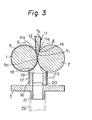
- a device according to an embodiment of the present invention shown in Figs. 1 through 3, comprises a pair of twisting rollers 1 and 2, a first duct 11, and second duct 15.
- the twisting rollers 1 and 2 are disposed substantially in a horizontal direction and in parallel to each other in a confronting manner with a small gap G therebetween.
- a spinning zone 12 having a valley shape is formed on the upper surface of the two rollers 1 and 2 along the gap G, in which a fiber bundle Y1 is prepared from a fiber Y 0 as stated later.
- Shafts la and 2a of both rollers are rotatably supported by ball bearings 4 and 5 secured to a machine frame 3.
- the first duct 11 is disposed above the spinning zone 12 for supplying an opened fiber Y 0 thereto.
- the second duct 15 is disposed just beneath the gap G for withdrawing air transporting the fiber through the spinning zone 12.
- One of the twisting rollers 1 and 2 for example, roller 1 shown at the upper side of Fig. 1 in this embodiment, has a plurality of peripheral grooves 9 arranged in parallel to each other and perpendicular to an axis of the roller 1 on substantially the entire outer surface thereof.
- the grooves 9 are equidistantly arranged, as shown in Fig. 4, they may be provided at different intervals from each other and also the width and profile of the groove 9 may be varied.
- the roller 1 is preferably made of a metal and the roller 2 is preferably wrapped with a synthetic rubber sheath, although the materials thereof are not necessarily restricted thereto.
- the first duct 11 has a triangular profile and is connected by a narrow base portion to known means for opening the fiber, such as a combing roller 10, and confronts the spinning zone 12 with a wide mouth portion l4, as illustrated in Figs. 2 and 3, whereby an individually separated fiber can be fed to the valley of the spinning zone 12.
- Lower ends of side walls lla of the mouth portion l4 are positioned closely to the upper surfaces of the rollers 1 and 2, and a lower end of a back wall llb is provided with a plate member 13 in a shape of triangle complementary to a profile of the spinning zone 12 for preventing extrication of the fiber from the spinning zone 12.
- a second embodiment of the present invention is illustrated, wherein the grooves 9e formed of a plurality of spirals are provided only on the right side part of the peripheral surface of the twisting roller le.
- the spiral groove 9e is preferably inclined in such a manner that the air flow directed opposite to the yarn withdrawal direction generates in the valley between the rollers due to rotation of the latter, because the parallelism of the fibers supplied in the spinning zone is improved.
- the surface portions of the two rollers without the grooves 9e are substantially in contact with each other, whereby the air flow can be shut in this portion and formation of the fiber bundle is carried out only in the other portion where the grooves 9e are provided.
- the spiral grooves may be replaced by the parallel ones as in the first embodiment shown in Figs. 1 through 6.
- Figure 8 illustrates a third embodiment of the present invention, in which both twisting rollers If and 2f are provided with parallel grooves 9f l and 9f - , respectively, on the entire peripheral surfaces thereof.
- Figure 9 illustrates a fourth embodiment of the present invention, in which spiral grooves 9g l and 9g 2 which intersect each other are provided on the entire peripheral surface of one twisting roller lg.
Landscapes
- Engineering & Computer Science (AREA)
- Mechanical Engineering (AREA)
- Textile Engineering (AREA)
- Spinning Or Twisting Of Yarns (AREA)
Applications Claiming Priority (2)
| Application Number | Priority Date | Filing Date | Title |
|---|---|---|---|
| JP16804784A JPS6147830A (ja) | 1984-08-11 | 1984-08-11 | 紡糸装置 |
| JP168047/84 | 1984-08-11 |
Publications (3)
| Publication Number | Publication Date |
|---|---|
| EP0171731A2 true EP0171731A2 (de) | 1986-02-19 |
| EP0171731A3 EP0171731A3 (en) | 1987-05-13 |
| EP0171731B1 EP0171731B1 (de) | 1989-10-25 |
Family
ID=15860838
Family Applications (1)
| Application Number | Title | Priority Date | Filing Date |
|---|---|---|---|
| EP19850109828 Expired EP0171731B1 (de) | 1984-08-11 | 1985-08-05 | Einrichtung zum Herstellen eines Fadens |
Country Status (3)
| Country | Link |
|---|---|
| EP (1) | EP0171731B1 (de) |
| JP (1) | JPS6147830A (de) |
| DE (1) | DE3573935D1 (de) |
Family Cites Families (4)
| Publication number | Priority date | Publication date | Assignee | Title |
|---|---|---|---|---|
| AT338666B (de) * | 1976-02-17 | 1977-09-12 | Fehrer Ernst Gmbh | Vorrichtung zum spinnen textiler fasern |
| DE2810184A1 (de) * | 1978-03-09 | 1979-09-13 | Barmag Barmer Maschf | Open-end-spinnvorrichtung |
| DE3307082A1 (de) * | 1983-03-01 | 1984-09-06 | Fritz 7347 Bad Überkingen Stahlecker | Oe-friktionsspinnvorrichtung |
| DE3308249A1 (de) * | 1983-03-09 | 1984-09-13 | Fritz 7347 Bad Überkingen Stahlecker | Oe-friktionsspinnvorrichtung |
-
1984
- 1984-08-11 JP JP16804784A patent/JPS6147830A/ja active Pending
-
1985
- 1985-08-05 EP EP19850109828 patent/EP0171731B1/de not_active Expired
- 1985-08-05 DE DE8585109828T patent/DE3573935D1/de not_active Expired
Also Published As
| Publication number | Publication date |
|---|---|
| EP0171731B1 (de) | 1989-10-25 |
| JPS6147830A (ja) | 1986-03-08 |
| DE3573935D1 (en) | 1989-11-30 |
| EP0171731A3 (en) | 1987-05-13 |
Similar Documents
| Publication | Publication Date | Title |
|---|---|---|
| US4315398A (en) | Open-end spinning apparatus | |
| JPH0227459B2 (de) | ||
| CS215068B2 (en) | Appliance for making the yearn | |
| EP0098380A2 (de) | Friktionsspinnvorrichtung | |
| US4676062A (en) | Method and device for the formation of spinning fibers | |
| US4241571A (en) | Apparatus for open-end or round-about spinning of a thread | |
| US4753066A (en) | Method of and apparatus for producing a yarn | |
| US4165600A (en) | Apparatus for open-end spinning of fibers | |
| US4823545A (en) | Method of and apparatus for false-twist spinning | |
| US4628679A (en) | Method and apparatus for the production of a yarn by open-end friction spinning | |
| US4606187A (en) | Fiber feeding air flow arrangement for open-end friction spinning | |
| EP0083251B1 (de) | Garnabzugsrohr eines "open-end" Spinnaggregates | |
| EP0171731B1 (de) | Einrichtung zum Herstellen eines Fadens | |
| US4696155A (en) | Friction spinning device containing a friction spinning means and method of use of the friction spinning device | |
| JPH1150339A (ja) | 糸を造るための方法および装置 | |
| US4392343A (en) | Friction spinning apparatus | |
| US4640089A (en) | Method and device for spinning a yarn in accordance with the open end-friction spinning principle | |
| EP0196312B1 (de) | Spinnen von garn | |
| JPH0641831A (ja) | 精紡機 | |
| GB2182068A (en) | Process and apparatus for making a yarn | |
| US4821505A (en) | Method and apparatus for spinning yarn | |
| US4731986A (en) | Process and device for open-end friction spinning | |
| US4744210A (en) | Method and device for producing a twisted thread from spinning fibers | |
| US4672804A (en) | Friction spinning apparatus | |
| US4759176A (en) | Arrangement for open-end friction spinning |
Legal Events
| Date | Code | Title | Description |
|---|---|---|---|
| PUAI | Public reference made under article 153(3) epc to a published international application that has entered the european phase |
Free format text: ORIGINAL CODE: 0009012 |
|
| AK | Designated contracting states |
Designated state(s): CH DE GB IT LI |
|
| 17P | Request for examination filed |
Effective date: 19860310 |
|
| PUAL | Search report despatched |
Free format text: ORIGINAL CODE: 0009013 |
|
| AK | Designated contracting states |
Kind code of ref document: A3 Designated state(s): CH DE GB IT LI |
|
| 17Q | First examination report despatched |
Effective date: 19890215 |
|
| GRAA | (expected) grant |
Free format text: ORIGINAL CODE: 0009210 |
|
| AK | Designated contracting states |
Kind code of ref document: B1 Designated state(s): CH DE GB IT LI |
|
| ITF | It: translation for a ep patent filed | ||
| REF | Corresponds to: |
Ref document number: 3573935 Country of ref document: DE Date of ref document: 19891130 |
|
| PLBI | Opposition filed |
Free format text: ORIGINAL CODE: 0009260 |
|
| 26 | Opposition filed |
Opponent name: SCHUBERT & SALZER MASCHINENFABRIK AG Effective date: 19900725 |
|
| PGFP | Annual fee paid to national office [announced via postgrant information from national office to epo] |
Ref country code: GB Payment date: 19910702 Year of fee payment: 7 |
|
| PGFP | Annual fee paid to national office [announced via postgrant information from national office to epo] |
Ref country code: CH Payment date: 19910827 Year of fee payment: 7 |
|
| ITTA | It: last paid annual fee | ||
| PGFP | Annual fee paid to national office [announced via postgrant information from national office to epo] |
Ref country code: DE Payment date: 19911031 Year of fee payment: 7 |
|
| RDAG | Patent revoked |
Free format text: ORIGINAL CODE: 0009271 |
|
| STAA | Information on the status of an ep patent application or granted ep patent |
Free format text: STATUS: PATENT REVOKED |
|
| 27W | Patent revoked |
Effective date: 19920525 |
|
| GBPR | Gb: patent revoked under art. 102 of the ep convention designating the uk as contracting state | ||
| REG | Reference to a national code |
Ref country code: CH Ref legal event code: PL |