EP0170809B1 - Arc furnace with a charging area on its side - Google Patents
Arc furnace with a charging area on its side Download PDFInfo
- Publication number
- EP0170809B1 EP0170809B1 EP85106662A EP85106662A EP0170809B1 EP 0170809 B1 EP0170809 B1 EP 0170809B1 EP 85106662 A EP85106662 A EP 85106662A EP 85106662 A EP85106662 A EP 85106662A EP 0170809 B1 EP0170809 B1 EP 0170809B1
- Authority
- EP
- European Patent Office
- Prior art keywords
- furnace
- charging material
- electrode
- arc
- space
- Prior art date
- Legal status (The legal status is an assumption and is not a legal conclusion. Google has not performed a legal analysis and makes no representation as to the accuracy of the status listed.)
- Expired
Links
- 239000000463 material Substances 0.000 claims abstract description 63
- 230000005855 radiation Effects 0.000 claims abstract description 3
- 239000007789 gas Substances 0.000 claims description 16
- 239000007788 liquid Substances 0.000 claims description 10
- 230000008859 change Effects 0.000 claims description 5
- 238000010891 electric arc Methods 0.000 claims description 4
- 230000007246 mechanism Effects 0.000 claims description 4
- 239000013070 direct material Substances 0.000 claims description 2
- 238000000638 solvent extraction Methods 0.000 claims 1
- 238000010309 melting process Methods 0.000 description 11
- 239000012615 aggregate Substances 0.000 description 5
- 239000003245 coal Substances 0.000 description 5
- 239000000155 melt Substances 0.000 description 5
- 238000010079 rubber tapping Methods 0.000 description 5
- XEEYBQQBJWHFJM-UHFFFAOYSA-N Iron Chemical compound [Fe] XEEYBQQBJWHFJM-UHFFFAOYSA-N 0.000 description 4
- QVGXLLKOCUKJST-UHFFFAOYSA-N atomic oxygen Chemical compound [O] QVGXLLKOCUKJST-UHFFFAOYSA-N 0.000 description 4
- 239000000203 mixture Substances 0.000 description 4
- 239000001301 oxygen Substances 0.000 description 4
- 229910052760 oxygen Inorganic materials 0.000 description 4
- 238000010438 heat treatment Methods 0.000 description 3
- 238000002844 melting Methods 0.000 description 3
- 230000008018 melting Effects 0.000 description 3
- 239000002184 metal Substances 0.000 description 3
- 229910052751 metal Inorganic materials 0.000 description 3
- 239000007787 solid Substances 0.000 description 3
- 238000006243 chemical reaction Methods 0.000 description 2
- 229910052742 iron Inorganic materials 0.000 description 2
- OKTJSMMVPCPJKN-UHFFFAOYSA-N Carbon Chemical compound [C] OKTJSMMVPCPJKN-UHFFFAOYSA-N 0.000 description 1
- 241000446313 Lamella Species 0.000 description 1
- 229910000805 Pig iron Inorganic materials 0.000 description 1
- 229910000831 Steel Inorganic materials 0.000 description 1
- 230000009471 action Effects 0.000 description 1
- 239000000654 additive Substances 0.000 description 1
- 230000015572 biosynthetic process Effects 0.000 description 1
- 238000007664 blowing Methods 0.000 description 1
- 239000000969 carrier Substances 0.000 description 1
- -1 coal or aggregates Chemical compound 0.000 description 1
- 238000006073 displacement reaction Methods 0.000 description 1
- 230000000694 effects Effects 0.000 description 1
- 238000000605 extraction Methods 0.000 description 1
- 230000002349 favourable effect Effects 0.000 description 1
- 229910002804 graphite Inorganic materials 0.000 description 1
- 239000010439 graphite Substances 0.000 description 1
- 229910001338 liquidmetal Inorganic materials 0.000 description 1
- 238000010310 metallurgical process Methods 0.000 description 1
- 238000005192 partition Methods 0.000 description 1
- 230000000717 retained effect Effects 0.000 description 1
- 239000002893 slag Substances 0.000 description 1
- 239000011343 solid material Substances 0.000 description 1
- 239000010959 steel Substances 0.000 description 1
- 239000000126 substance Substances 0.000 description 1
- 230000007704 transition Effects 0.000 description 1
Images
Classifications
-
- F—MECHANICAL ENGINEERING; LIGHTING; HEATING; WEAPONS; BLASTING
- F27—FURNACES; KILNS; OVENS; RETORTS
- F27D—DETAILS OR ACCESSORIES OF FURNACES, KILNS, OVENS, OR RETORTS, IN SO FAR AS THEY ARE OF KINDS OCCURRING IN MORE THAN ONE KIND OF FURNACE
- F27D11/00—Arrangement of elements for electric heating in or on furnaces
- F27D11/08—Heating by electric discharge, e.g. arc discharge
-
- F—MECHANICAL ENGINEERING; LIGHTING; HEATING; WEAPONS; BLASTING
- F27—FURNACES; KILNS; OVENS; RETORTS
- F27B—FURNACES, KILNS, OVENS, OR RETORTS IN GENERAL; OPEN SINTERING OR LIKE APPARATUS
- F27B3/00—Hearth-type furnaces, e.g. of reverberatory type; Tank furnaces
- F27B3/10—Details, accessories, or equipment peculiar to hearth-type furnaces
- F27B3/18—Arrangements of devices for charging
- F27B3/183—Charging of arc furnaces vertically through the roof, e.g. in three points
- F27B3/186—Charging in a vertical chamber adjacent to the melting chamber
-
- F—MECHANICAL ENGINEERING; LIGHTING; HEATING; WEAPONS; BLASTING
- F27—FURNACES; KILNS; OVENS; RETORTS
- F27D—DETAILS OR ACCESSORIES OF FURNACES, KILNS, OVENS, OR RETORTS, IN SO FAR AS THEY ARE OF KINDS OCCURRING IN MORE THAN ONE KIND OF FURNACE
- F27D1/00—Casings; Linings; Walls; Roofs
- F27D1/18—Door frames; Doors, lids, removable covers
- F27D1/1808—Removable covers
- F27D1/1816—Removable covers specially adapted for arc furnaces
-
- H—ELECTRICITY
- H05—ELECTRIC TECHNIQUES NOT OTHERWISE PROVIDED FOR
- H05B—ELECTRIC HEATING; ELECTRIC LIGHT SOURCES NOT OTHERWISE PROVIDED FOR; CIRCUIT ARRANGEMENTS FOR ELECTRIC LIGHT SOURCES, IN GENERAL
- H05B7/00—Heating by electric discharge
- H05B7/02—Details
- H05B7/10—Mountings, supports, terminals or arrangements for feeding or guiding electrodes
Definitions
- the invention relates to an electric arc furnace with at least one receiving space for charging goods, which is provided on one side of the furnace vessel, according to the preamble of claim 1.
- the arc furnace of this type which has become known from EP-A1-56 773, the arc furnace has a lateral bulge, the sole of which is higher than the sole of the hearth.
- the input material is charged in this bulged part and stored as a pile on the raised sole.
- the hot furnace gases are passed through the upper part of this pile, and the pile is also exposed to the radiant heat of the arc furnace and is thereby heated.
- the preheated feed is fed in batches from the lowest section of the pile into the oven hearth.
- the sole of the side bulge of the furnace is sloping towards the stove.
- the preheated bottom section of the charge column can be conveyed through the connection zone into the oven hearth, i.e. the insert can be fed to the melting vessel in batches.
- a charging device attached to the top of the charge material preheater allows the charge material to be fed continuously into the preheater and a gas outlet located in the vicinity thereof allows the furnace gases cooled in the heat exchange with the charge material within the charge material column to be drawn off.
- the object of the invention is to increase the possible heat transfer into the charge material in an arc furnace according to the preamble of claim 1 and thus to shorten the heating time of the charge material. It should make better use of the radiant heat and the resulting hot furnace gases when heating the charging material and thereby improve the thermal efficiency.
- the heat load on the furnace walls should be reduced.
- a continuous flow of material from the receiving space for the goods to be charged into the oven hearth and thus more uniform operating conditions are to be made possible. Temperature fluctuations and fluctuations in the chemical composition of the weld pool should be reduced.
- the electrodes can be brought into the immediate vicinity of the receiving space for the cargo to be provided on one side of the furnace vessel, so that the radiant heat generated by the arcs is intensified
- Charge material can act and at the same time the radiation exposure of the free wall areas of the arc furnace is reduced.
- the hot gases that are generated in the area of the arcs, particularly when coal and other feedstocks are added, are introduced directly into the charge material, so that their sensible heat can be optimally utilized.
- burners and / or nozzles are additionally provided on the lower area of the receiving space for the goods to be charged, this area can be additionally heated or oxygen, coal or other additives can be introduced for temperature control and control of the composition of the melt pool.
- the bottom of the receiving space for the charge is arranged so deep that when a liquid sump is formed in the furnace, it extends into the receiving space and enables a direct material and conductive heat exchange in the lowest zone of the accumulated charge. In this way, an additional heat flow is made possible for the lowermost zone of the charge column standing in the liquid sump. In this zone there is an intensive exchange of material and heat, which is caused by the bath movement that always occurs in the stove. In this way, the melt overheated in the area of the arcs emits heat in this zone, as a result of which the material which has already been preheated is melted in this zone.
- the liquefied material flows continuously from the receiving space for the charge material into the liquid melt pool of the furnace, so that the operating conditions can be kept largely constant here.
- the zone of the festival Liquid transition also takes place chemical-metallurgical reactions, such as slag formation, carburization, etc., which can be promoted by the targeted addition of oxygen, coal or aggregates.
- chemical-metallurgical reactions such as slag formation, carburization, etc., which can be promoted by the targeted addition of oxygen, coal or aggregates.
- the thermal conditions in the furnace be kept constant and set to an optimal working point, but also larger fluctuations in the composition of the melt can be prevented or the composition of the melt can be controlled.
- a change in position of either the arc electrodes or the furnace vessel together with the receiving space brings the electrodes back to the center of the furnace and in this position the bath to heated to the required tapping temperature.
- the movability of the electrodes or the arc furnace makes it possible to change the position of the heat source within the furnace in the course of the melting process so that both the melting process and metallurgical processes can run optimally within the furnace.
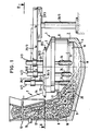
- the furnace assembly shown in FIGS. 1 and 2 in a vertical section and in a plan view contains an electric arc furnace 1 consisting of a furnace vessel 2 and a removable cover 3, through which 3 electrodes 4 / 1.4 / 2 and 4/3 are passed.
- the furnace vessel 2 is formed by a stove 5 made of a refractory lining and preferably by liquid-cooled wall elements 6.
- a shaft-shaped charge preheater 7 with a receiving space (interior) 8 for charge goods is arranged, which in a region adjacent to its base 9 is connected by a connecting zone 10 the interior 11 of the furnace vessel 2 is connected.
- the Chargiergutvor lockerr 7 has a gas-tight feed device 12, z. B. a double bell closure of known type, and a gas outlet 13 to which a suction device, not shown, is connected.
- the charge preheater 7 extends approximately over a quarter of the circumference of the furnace vessel 2, the shaft wall 14 of the charge preheater facing the furnace vessel being adapted to the outer contour of the furnace vessel. From Fig. 1 it can be seen that the cross section of the interior 8 of the charge preheater 7 extends downward. This is intended to enable unhindered sinking of the cargo in the cargo preheater. Burners 15 or nozzles for blowing in gases, such as oxygen, or solids, such as coal or aggregates, open into the connecting zone 10.
- gases such as oxygen, or solids, such as coal or aggregates
- the feed material 16 charged in the charge material preheater 7 can consist of metal scrap, in particular steel scrap and other iron carriers, such as lumpy pig iron, sponge iron and aggregates. It forms in the charge material preheater 7 a gas-permeable pouring column referred to as the charge goods column 17.
- the molten metal (sump) formed in the arc furnace 1 is designated 18, the melt level 19.
- An eccentric bottom cut 21 is provided in the bottom of the oven hearth 5, which is shown in broken lines in FIG. 2.
- the furnace vessel 2 is designed to be tiltable.
- the tilt level, i.e. the plane in which the tilting movement takes place is designated by 22.
- the charge preheater 7 is arranged in a direction transverse to the tilting plane of the furnace vessel.
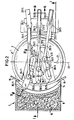
- Each of the electrodes 4/1 to 4/3 contains a liquid-cooled metallic upper part 23 and a lower part 24 which forms the electrode tip and is made of an edible material, such as graphite, which is detachably attached to the upper part 23.
- Each electrode 4/1, 4/2 or 4/3 is clamped with its upper part 23 into an electrode support arm 25/1, 25/2 or 25/3, which is supported by an electrode lifting mechanism 26/1, 26/2 or 26/3 can be raised and lowered.
- the electrode hoists 26/1 to 26/3 are located on the receiving space for the cargo, i.e. the shaft-shaped charge material preheater 7 opposite side next to the furnace vessel 2.
- each of the electrode support arms 25/1 to 25/3 is one Horizontal guide 27/1, 27/2 or 27/3 connected to the associated hoist 26/1, 26/2 or 26/3 and by a two-way drive, which is not shown in the drawing, along the guide movable back and forth.
- the guides 27/1 and 27/3 of the two outer electrode support arms 25/1 and 25/3 are each curved outwards, so that when the electrode support arms 25/1 and 25/3 move back and forth, they move by a limited angle in the direction horizontal plane are pivotable.
- the trajectories of the central axes of the electrodes 4/1 to 4/3 during the forward and backward movement of the electrode support arms along the guides 27/1 to 27/3 are shown in dash-dot lines in FIG.
- the movement paths 28/1 and 28/3 are also curved outwards.
- the ends of the trajectories are marked by cross lines, which thus illustrate the extreme positions of the central axes of the electrodes. In the left extreme position shown in FIG. 2, the electrodes 4 / 1.4 / 2 and 4/3 each have approximately the same distance from the receiving space 8.
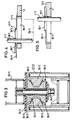
- the horizontal guides 27/1 to 27/3 for the electrode support arms 25/1 to 25/3 can be designed according to FIG. 3.
- This FIG. Shows the section 111-111 of FIG. 2 on an enlarged scale.
- the guide 27/2 contains two mutually opposite, trapezoidal cross-section-shaped slide rails 29/2, each with an upper and a lower slide path 30/2, which pass through a pad made of sliding material.
- the sliding surfaces of a slide 31/2 rest on the slideways, which thereby fixes its position and is displaceable along the rails 29/2.
- the slide 31/2 carries the support arm 25/2, which is attached to the slide 31/2 with the interposition of a cover plate 32/2 and an insulating plate 33/2 by means of a screw bolt 34/2.
- the insulating plate 33/2 which has the same length as the slide 31/2, is also shown in part in FIG. 2. From this illustration it can be seen that the slide 31/2 extends for stability reasons over about a third to half the length of the guide 27/2.
- the guides 27/1 and 27/3 for the two outer support arms 25/1 and 25/3 have a similar structure. As can be seen from Fig. 2, however, they are curved, i.e. the rails 29/1 and 29/3 in question also have a corresponding curvature in plan view.
- the cover has a slot-shaped electrode passage for each electrode which is adapted to its movement path.
- the slot-shaped electrode bushings are covered by cover slats 35/1, 36/1, 37/1 to 35/3, 36/3, 37/3 which can be moved along the horizontal movement path, one of which has a passage opening adapted to the electrode cross section.
- the cover slats close the slot-shaped electrode feedthrough in the cover in every position of the electrode along its path of movement 28/1, 28/2 and 28/3.
- the slot-shaped electrode leadthrough in the cover 3 visible in the illustration according to FIGS. 4 and 5 is designated 38/1
- the passage opening in the cover plate 36/1 adapted to the electrode cross section is designated 39/1.
- the ends of the middle cover lamella 36/1 each overlap one end of the outer cover lamellae 35/1 and 37/1.
- drivers 40/1 are provided which, when the electrode 4/1 is displaced along the movement path 28/1 and the movement of the middle cover slat 36/1 caused thereby, each take the outer slats along with them and thus Ensure that the electrode bushing 38/1 is completely closed in every position of the electrode 4/1.
- the solid, lumpy feed material 16 is charged into the receiving space 8 of the charge material preheater 7 by the charging device 12 until a sufficient column 17 has formed. In the area of the connection zone 10, the solid feed material partly reaches the furnace hearth due to the natural angle of repose 41 of the bed.
- the electrodes 4/1 to 4/3 are now moved in the direction of the charge preheater 7 and the melting process is started by lowering the electrodes in the region of the bed.
- the liquid metal sump that forms collects in the stove and causes an intensive material and heat exchange through the bath movement in the lowest zone of the charge column.
- desired metallurgical conversions can also take place, which are controlled by targeted supply of oxygen, coal or aggregates in the area indicated by the burners 15 or by aggregates admixed with the charge.
- the burner 15 can also be used to introduce additional heat.
- the feed material 16 of the pouring column 17 sinks down in order to also be melted in the lowest zone.
- the cross-section of the Interior 8 of the charge material preheater 7 expanded downwards.
- the electrodes 4/1 to 4/3 are in the position adjacent to the shaft furnace 7, that is to say in the representation according to FIG. 2, in the vicinity or at the left end position of the movement paths 28/1 to 28/3, the radiation energy the arcs are introduced to an increased extent in the lower area of the charge column and thus optimally used for the melting process.
- the furnace exhaust gases which, due to the extraction via the gas outlet 13, reach the charging material column directly from the arcing areas.
- the electrodes When a sufficient amount of feed material has melted, the electrodes are moved back into the right end position of the movement paths 28/1 to 28/3 shown in FIG. 2 and the bath is brought to the required tapping temperature.
- the tapping takes place via the tapping device 21 provided in the bottom of the arc furnace. Part of the metal sump is preferably retained in the furnace vessel for the next melting process.
- the electrode can be moved horizontally, the arcs can always be brought into the most favorable position with regard to the melting process, the heating of the liquid melting bath and the loading of the furnace walls. Any intermediate positions are possible along the movement paths 28/1 to 28/3 of the electrodes 4/1 to 4/3. In this way it is also possible, during the melting process, to have the arcs burn only on an existing liquid sump immediately adjacent to the still solid material and thus to enable more uniform operating conditions. Since only the relative position of the electrodes within the furnace vessel is important, it is also possible to move the furnace vessel 2 together with the receiving space 8 instead of the electrodes.
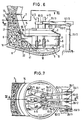
- each of the electrodes 4/1, 4/2 and 4/3 is clamped in a telescopically extendable electrode support arm 51/1, 51/2 and 51/3.
- the guides 52/1, 52/2 or 52/3 for these electrode support arms can be raised and lowered by means of electrode hoists 26/1, 26/2 or 26/3 and also by a limited angle about vertical axes 53/1, 53 / 2 or 53/3 rotatable.
- the guides 52/1 to 52/3 are thus each connected to the associated electrode lifting mechanism 26/1 to 26/3 via a connection which is rotatable within a limited angle and is equipped with a drive.
- the arc electrodes 4/1 to 4/3 are of a triangular arrangement in the plan view in the center of the furnace vessel, as shown in FIG. 7, in one arcuate arrangement adjacent to the receiving space for the cargo and movable back.
- a limited possibility of rotation (not shown) of each of the two outer support arms 51/1 and 51/3 about their longitudinal axes 54/1 and 54/3 is provided.
- the outer electrodes 4/1 and 4/3 can be inclined by a small angle, so that in addition to the change in the distance between the electrode tips due to the predetermined movement paths of the electrodes, a change in the distance is possible by inclination.
- connection zone 10 extends obliquely upwards from the interior 11 of the furnace vessel 2 to the interior 8 of the charge material preheater 7 and a partition 56 provided with gas passage openings 55 is arranged in the expanded region.
- the hot furnace gases can be introduced into this column over a larger cross section of the charge column 17.
Landscapes
- Engineering & Computer Science (AREA)
- Mechanical Engineering (AREA)
- General Engineering & Computer Science (AREA)
- Physics & Mathematics (AREA)
- Plasma & Fusion (AREA)
- Vertical, Hearth, Or Arc Furnaces (AREA)
- Refinement Of Pig-Iron, Manufacture Of Cast Iron, And Steel Manufacture Other Than In Revolving Furnaces (AREA)
Abstract
Description
Die Erfindung betrifft einen Lichtbogenofen mit wenigstens einem auf einer Seite des Ofengefäßes vorgesehenen Aufnahmeraum für Chargiergut gemäß dem Oberbegriff des Anspruchs 1.The invention relates to an electric arc furnace with at least one receiving space for charging goods, which is provided on one side of the furnace vessel, according to the preamble of claim 1.
Bei dem durch die EP-A1-56 773 bekannt gewordenen Lichtbogenofen dieser Art weist der Lichtbogenofen eine seitliche Ausbuchtung auf, deren Sohle höher liegt als die Sohle des Herdes. In diesen ausgebuchteten Teil wird das Einsatzgut chargiert und als Haufwerk auf der erhöhten Sohle gelagert. Durch den oberen Teil dieses Haufwerks werden die heißen Ofengase hindurchgeleitet, außerdem ist das Haufwerk der Strahlungshitze des Lichtbogenofens ausgesetzt und wird hierdurch erwärmt. Durch einen Schieber wird das vorerhitzte Einsatzgut jeweils aus dem untersten Abschnitt des Haufwerks schubweise in den Ofenherd befördert. Die Sohle der seitlichen Ausbuchtung des Ofens ist zum Ofenherd hin abfallend ausgebildet.In the arc furnace of this type which has become known from EP-A1-56 773, the arc furnace has a lateral bulge, the sole of which is higher than the sole of the hearth. The input material is charged in this bulged part and stored as a pile on the raised sole. The hot furnace gases are passed through the upper part of this pile, and the pile is also exposed to the radiant heat of the arc furnace and is thereby heated. The preheated feed is fed in batches from the lowest section of the pile into the oven hearth. The sole of the side bulge of the furnace is sloping towards the stove.
Durch die US-PS-3 441 651 ist ein Lichtbogenofen mit einem an einer Seite des Ofengefäßes angeordneten, schachtförmigen Chargiergutvorwärmer bekannt geworden, dessen Innenraum mit dem Innenraum des Ofengefäßes durch eine etwa in mittlerer Höhe des Ofengefäßes vorgesehene Verbindungszone verbunden ist, die einerseits dazu dient, die beim Schmelzprozeß entstehenden heißen Ofengase in eine im Chargiergutvorwärmer gebildete Säule aus Einsatzmaterial ein- und im Gegenstrom zu dem absinkenden Einsatzmaterial hindurchzuleiten, dieses vorzuwärmen und andererseits als Austragöffnung für das erhitzte Chargiergut im Bodenbereich des Chargiergutvorwärmers. Mittels eine hydraulisch betätigbaren Schiebers kann jeweils der vorgewärmte unterste Abschnitt der Chargiergutsäule durch die Verbindungszone in den Ofenherd befördert, d.h. das Einsatz gut schubweise dem Schmelzgefäß zugeführt werden. Eine am Chargiergutvorwärmer oben angebrachte Chargiervorrichtung erlaubt eine kontinuierliche Zufuhr des Chargiergutes in den Vorwärmer und ein in der Nähe hiervon angebrachter Gasauslaß einen Abzug der im Wärmetausch mit dem Chargiergut innerhalb der Chargiergutsäule abgekühlten Ofengase.From US Pat. No. 3,441,651, an arc furnace with a shaft-shaped charge preheater arranged on one side of the furnace vessel has become known, the interior of which is connected to the interior of the furnace vessel by a connecting zone provided at approximately the middle height of the furnace vessel, which serves on the one hand for this purpose to introduce the hot furnace gases formed during the melting process into a column of feed material formed in the charge material preheater and to pass them in countercurrent to the sinking feed material, to preheat it and on the other hand as a discharge opening for the heated charge material in the bottom area of the charge material preheater. By means of a hydraulically actuated slide, the preheated bottom section of the charge column can be conveyed through the connection zone into the oven hearth, i.e. the insert can be fed to the melting vessel in batches. A charging device attached to the top of the charge material preheater allows the charge material to be fed continuously into the preheater and a gas outlet located in the vicinity thereof allows the furnace gases cooled in the heat exchange with the charge material within the charge material column to be drawn off.
Aufgabe der Erfindung ist es bei einem Lichtbogenofen gemäß dem Gattungsbegriff des Anspruchs 1 den möglichen Wärmetransport in das Chargiergut zu vergrößern und damit die Aufheizzeit des Chargiergutes zu verkürzen. Es soll eine bessere Ausnutzung der Strahlungshitze sowie der entstehenden heißen Ofengase beim Aufheizen des Chargiergutes ermöglicht und dadurch der thermische Wirkungsgrad verbessert werden. Die Hitzebeanspruchung der Ofenwände soll verringert werden. Außerdem soll ein kontinuierlicher Materialfluß aus dem Aufnahmeraum für das Chargiergut in den Ofenherd und damit sollen gleichmäßigere Betriebsbedingungen ermöglicht werden. Temperaturschwankungen und Schwankungen in der chemischen Zusammensetzung des Schmelzbades sollen herabgesetzt werden.The object of the invention is to increase the possible heat transfer into the charge material in an arc furnace according to the preamble of claim 1 and thus to shorten the heating time of the charge material. It should make better use of the radiant heat and the resulting hot furnace gases when heating the charging material and thereby improve the thermal efficiency. The heat load on the furnace walls should be reduced. In addition, a continuous flow of material from the receiving space for the goods to be charged into the oven hearth and thus more uniform operating conditions are to be made possible. Temperature fluctuations and fluctuations in the chemical composition of the weld pool should be reduced.
Die Erfindung ist durch die Merkmale des Anspruchs 1 gekennzeichnet. Vorteilhafte Ausgestaltungen der Erfindung sind den Unteransprüchen zu entnehmen.The invention is characterized by the features of claim 1. Advantageous embodiments of the invention can be found in the subclaims.
Bei der erfindungsgemäßen Lösung können durch eine Positionsänderung entweder der Lichtbogenelektroden oder des Ofengefäßes zusammen mit dem Aufnahmeraum die Elektroden bis in die unmittelbare Nachbarschaft des auf einer Seite des Ofengefäßes vorgesehenen Aufnahmeraums für das Chargiergut gebracht werden, so daß die durch die Lichtbögen erzeugte Strahlungshitze verstärkt auf das Chargiergut einwirken kann und gleichzeitig die Strahlungsbelastung der freien Wandbereiche des Lichtbogenofens verringert wird. Die insbesondere bei Zusatz von Kohle und anderen Einsatzmaterialien im Bereich der Lichtbögen entstehenden heißen Gase werden unmittelbar in das Chargiergut eingeleitet, so daß ihre fühlbare Wärme optimal ausgenutzt werden kann. Durch diese beiden Effekte läßt sich der thermische Wirkungsgrad wesentlich verbessern.In the solution according to the invention, by changing the position of either the arc electrodes or the furnace vessel together with the receiving space, the electrodes can be brought into the immediate vicinity of the receiving space for the cargo to be provided on one side of the furnace vessel, so that the radiant heat generated by the arcs is intensified Charge material can act and at the same time the radiation exposure of the free wall areas of the arc furnace is reduced. The hot gases that are generated in the area of the arcs, particularly when coal and other feedstocks are added, are introduced directly into the charge material, so that their sensible heat can be optimally utilized. These two effects can significantly improve the thermal efficiency.
Durch die unmittelbare Einwirkung der Lichtbögen auf den unteren Bereich des Haufwerks bzw. der Säule aus Chargiergut läßt sich dieser in den teigigen und flüssigen Zustand überführen, so daß ein kontinuierlicher Zufluß aus dem Aufnahmeraum für das Chargiergut in den Ofenherd ermöglicht wird.Due to the direct action of the arcs on the lower area of the pile or the column of charge material, this can be converted into the doughy and liquid state, so that a continuous inflow from the receiving space for the charge material into the oven hearth is made possible.
Werden zusätzlich auf den unteren Bereich des Aufnahmeraums für das Chargiergut gerichtete Brenner und/oder Düsen vorgesehen, so kann dieser Bereich zusätzlich erhitzt werden oder es können Sauerstoff, Kohle oder sonstige Zuschläge zur Temperatursteuerung und Steuerung der Zusammensetzung des Schmelzbades eingebracht werden.If burners and / or nozzles are additionally provided on the lower area of the receiving space for the goods to be charged, this area can be additionally heated or oxygen, coal or other additives can be introduced for temperature control and control of the composition of the melt pool.
Vorzugsweise ist der Boden des Aufnahmeraums für das Chargiergut so tief angeordnet, daß sich bei Bildung eines flüssigen Sumpfes im Ofenherd dieser in den Aufnahmeraum erstreckt und in der untersten Zone des aufgehäuften Chargierguts einen unmittelbaren Stoff- und konduktiven Wärmeaustausch ermöglicht. Auf diese Weise wird ein zusätzlicher Wärmefluß für die unterste Zone der im flüssigen Sumpf stehenden Chargiergutsäule ermöglicht. In dieser Zone findet ein intensiver Stoff- und Wärmeaustausch statt, der durch die im Ofenherd stets auftretende Badbewegung verursacht wird. Die im Bereich der Lichtbögen überhitzte Schmelze gibt auf diese Weise in dieser Zone Wärme ab, wodurch das bereits vorerhitzte Material in dieser Zone aufgeschmolzen wird. Das verflüssigte Material fließt aus dem Aufnahmeraum für das Chargiergut kontinuierlich in das flüssige Schmelzbad des Ofenherdes, so daß hier die Betriebsbedingungen weitgehend konstant gehalten werden können. In der Zone des Fest-Flüssig-Übergangs finden darüber hinaus chemisch-metallurgische Umsetzungen, wie Schlackenbildung, Aufkohlung etc. statt, die durch gezielte Zufuhr von Sauerstoff, Kohle oder Zuschlägen begünstigt werden können. Es können somit nicht nur die thermischen Bedingungen im Ofenherd konstant gehalten und auf einen optimalen Arbeitspunkt eingestellt werden, sondern auch größere Schwankungen der Zusammensetzung der Schmelze verhindert bzw. die Zusammensetzung der Schmelze gesteuert werden.Preferably, the bottom of the receiving space for the charge is arranged so deep that when a liquid sump is formed in the furnace, it extends into the receiving space and enables a direct material and conductive heat exchange in the lowest zone of the accumulated charge. In this way, an additional heat flow is made possible for the lowermost zone of the charge column standing in the liquid sump. In this zone there is an intensive exchange of material and heat, which is caused by the bath movement that always occurs in the stove. In this way, the melt overheated in the area of the arcs emits heat in this zone, as a result of which the material which has already been preheated is melted in this zone. The liquefied material flows continuously from the receiving space for the charge material into the liquid melt pool of the furnace, so that the operating conditions can be kept largely constant here. In the zone of the festival Liquid transition also takes place chemical-metallurgical reactions, such as slag formation, carburization, etc., which can be promoted by the targeted addition of oxygen, coal or aggregates. Not only can the thermal conditions in the furnace be kept constant and set to an optimal working point, but also larger fluctuations in the composition of the melt can be prevented or the composition of the melt can be controlled.
Wenn sich im Ofenherd ein ausreichender Sumpf gebildet hat, spätestens aber wenn der Schmelzspiegel die Abstichhöhe erreicht hat, werden durch eine Positionsänderung entweder der Lichtbogenelektroden oder des Ofengefäßes zusammen mit dem Aufnahmeraum die Elektroden wieder in die Mitte des Ofens zurückgebracht und in dieser Position das Bad bis zur erforderlichen Abstichtemperatur erhitzt. Durch die Verfahrbarkeit der Elektroden oder des Lichtbogenofens ist es so möglich, im Verlauf des Schmelzprozesses die Position der Hitzequelle innerhalb des Ofens so zu verändern, daß sowohl der Einschmelzprozeß als auch metallurgische Prozesse innerhalb des Ofens optmal ablaufen können.If a sufficient sump has formed in the furnace, or at the latest when the melting level has reached the tapping height, a change in position of either the arc electrodes or the furnace vessel together with the receiving space brings the electrodes back to the center of the furnace and in this position the bath to heated to the required tapping temperature. The movability of the electrodes or the arc furnace makes it possible to change the position of the heat source within the furnace in the course of the melting process so that both the melting process and metallurgical processes can run optimally within the furnace.
Die Erfindung wird durch Ausführungsbeispiele anhand von 7 Figuren näher erläutert. Es zeigen
- Fig. 1 in schematischer Darstellung einen senkrechten Schnitt durch einen Lichtbogenofen mit einem auf einer Seite des Ofengefäßes angeordneten Aufnahmeraum für Chargiergut,
- Fig. 2 eine Draufsicht, teilweise geschnitten, der Ausführungsform nach Fig. 1,
- Fig. 3 in vergrößerter Darstellung den Schnitt 111-111 von Fig. 2,
- Fig. 4 den Schnitt IV-IV von Fig. 2,
- Fig. 5 einen der Fig. 4 entsprechenden Schnitt bei anderer Position der Elektrode,
- Fig. 6 und 7 in den Fig. 1 und 2 entsprechenden Ansichten eine zweite Ausführungsform der Erfindung.
- 1 is a schematic representation of a vertical section through an electric arc furnace with a receiving space for charge goods arranged on one side of the furnace vessel,
- 2 is a plan view, partially in section, of the embodiment of FIG. 1,
- 3 is an enlarged view of section 111-111 of FIG. 2,
- 4 shows the section IV-IV of FIG. 2,
- 5 shows a section corresponding to FIG. 4 in a different position of the electrode,
- 6 and 7 in FIGS. 1 and 2 corresponding views of a second embodiment of the invention.
Das in den Fig. 1 und 2 in einem senkrechten Schnitt und in einer Draufsicht dargestellte Ofenaggregat enthält einen Lichtbogenofen 1 aus einem Ofengefäß 2 und einem abnehmbaren Deckel 3, durch den 3 Elektroden 4/1,4/2 und 4/3 hindurchgeführt sind. Das Ofengefäß 2 ist durch einen Ofenherd 5 aus einer feuerfesten Ausmauerung und durch vorzugsweise flüssigkeitsgekühlte Wandelemente 6 gebildet. Auf einer Seite des Ofengefäßes, das im vorliegenden Fall wie Fig. 2 zeigt einen runden Querschnitt aufweist, ist ein schachtförmiger Chargiergutvorwärmer 7 mit einem Aufnahmeraum (Innenraum) 8 für Chargiergut angeordnet, der in einem an seinen Boden 9 angrenzenden Bereich durch eine Verbindungszone 10 mit dem Innenraum 11 des Ofengefäßes 2 verbunden ist. Der Chargiergutvorwärmer 7 weist in seinem oberen Bereich eine gasdichte Beschickungseinrichtung 12, z. B. einen Doppelglockenverschluß bekannter Bauart, sowie einen Gasauslaß 13 auf, an den eine nicht dargestellt Absaugvorrichtung angeschlossen ist.The furnace assembly shown in FIGS. 1 and 2 in a vertical section and in a plan view contains an electric arc furnace 1 consisting of a
Wie Fig. 2 zeigt, erstreckt sich der Chargiergutvorwärmer 7 etwa über ein Viertel des Umfangs des Ofengefäßes 2, wobei die dem Ofengefäß zugekehrte Schachtwand 14 des Chargiergutvorwärmers der Außenkontur des Ofengefäßes angepaßt ist. Aus Fig. 1 ist ersichtlich, daß sich der Querschnitt des Innenraums 8 des Chargiergutvorwärmers 7 nach unten erweitert. Hierdurch soll ein unbehindertes Absinken des Chargierguts im Chargiergutvorwärmer ermöglicht werden. In die Verbindungszone 10 münden Brenner 15 bzw. Düsen zum Einblasen von Gasen, wie Sauerstoff, oder von Feststoffen, wie Kohle oder Zuschlägen.As shown in FIG. 2, the charge preheater 7 extends approximately over a quarter of the circumference of the
Das in den Chargiergutvorwärmer 7 chargierte Einsatzgut 16 kann aus Metallschrott, insbesondere Stahlschrott und anderen Eisenträgern, wie stückigem Roheisen, Eisenschwamm sowie Zuschlägen bestehen. Es bildet im Chargiergutvorwärmer 7 eine als Chargiergutsäule 17 bezeichnete gasdurchlässige Schüttsäule. Die im Lichtbogenofen 1 gebildete Metallschmelze (Sumpf) ist mit 18, der Schmelzspiegel mit 19 bezeichnet.The
Der Boden 9 des Chargiergutvorwärmers 7, der vorzugsweise zum Ofenherd 5 hin abfallend ausgebildet ist, ist so tief angeordnet, daß sich über einen wesentlichen Teil des Einschmelzprozesses ein im Ofenherd gebildeter flüssiger Sumpf 18 in die unterste Zone 20 der Chargiergutsäule 17 erstreckt und hier einen unmittelbaren Stoff- und konduktiven Wärmeaustausch ermöglicht. Im Boden des Ofenherdes 5 ist ein exzentrischer Bodenabstich 21 vorgesehen, der in Fig. 2 gestrichelt dargestellt ist. Das Ofengefäß 2 ist im vorliegenden Fall kippbar ausgebildet. Die Kippebene, d.h. die Ebene in der die Kippbewegung erfolgt, ist mit 22 bezeichnet. Der Chargiergutvorwärmer 7 ist in einer quer zur Kippebene des Ofengefäßes verlaufenden Richtung angeordnet.The
Jede der Elektroden 4/1 bis 4/3 enthält einen flüssigkeitsgekühlten metallischen oberen Teil 23 und einen die Elektrodenspitze bildenden unteren Teil 24 aus verzehrbarem Material, wie Graphit, der am oberen Teil 23 lösbar befestigt ist. Jede Elektrode 4/1, 4/2 bzw. 4/3 ist mit ihrem oberen Teil 23 in einen Elektrodentragarm 25/1, 25/2 bzw. 25/3 eingespannt, der durch ein Elektrodenhubwerk 26/1, 26/2 bzw. 26/3 anhebbar und absenkbar ist. Die Elektrodenhubwerke 26/1 bis 26/3 sind auf der dem Aufnahmeraum für das Chargiergut, d.h. dem schachtförmigen Chargiergutvorwärmer 7 gegenüberliegenden Seite neben dem Ofengefäß 2 angeordnet.Each of the electrodes 4/1 to 4/3 contains a liquid-cooled metallic
Bei dem in den Fig. 1 und 2 dargestellten Ausführungsbeispiel ist jeder der Elektrodentragarme 25/1 bis 25/3 über eine Horizontalführung 27/1, 27/2 bzw. 27/3 mit dem zugehörigen Hubwerk 26/1, 26/2 bzw. 26/3 verbunden und durch einen in zwei Richtungen wirkenden Antrieb, der in der Zeichnung nicht dargestellt ist, längs der Führung vorund zurück bewegbar. Die Führungen 27/1 und 27/3 der beiden äußeren Elektrodentragarme 25/1 und 25/3 sind jeweils nach außen gekrümmt, so daß bei der Vor- und Rückbewegung der Elektrodentragarme 25/1 und 25/3 diese um einen begrenzten Winkel in der horizontalen Ebene schwenkbar sind. Die Bewegungsbahnen der Mittelachsen der Elektroden 4/1 bis 4/3 bei der Vorwärts- und Rückwärtsbewegung der Elektrodentragarme längs der Führungen 27/1 bis 27/3 sind in Fig. 2 strichpunktiert dargestellt und mit 28/1 bis 28/3 bezeichnet. Es ist ersichtlich, daß aufgrund der gekrümmten Führungen 27/1 und 27/3 die Bewegungsbahnen 28/1 und 28/3 ebenfalls nach außen gekrümmt sind. Die Enden der Bewegungsbahnen sind durch Querstriche markiert, die somit die Extremlagen der Mittelachsen der Elektroden veranschaulichen. In der in Fig. 2 dargestellten linken Extremlage weisen die Elektroden 4/1,4/2 und 4/3 jeweils etwa den gleichen Abstand zum Aufnahmeraum 8 auf.In the embodiment shown in FIGS. 1 and 2, each of the electrode support arms 25/1 to 25/3 is one Horizontal guide 27/1, 27/2 or 27/3 connected to the associated hoist 26/1, 26/2 or 26/3 and by a two-way drive, which is not shown in the drawing, along the guide movable back and forth. The guides 27/1 and 27/3 of the two outer electrode support arms 25/1 and 25/3 are each curved outwards, so that when the electrode support arms 25/1 and 25/3 move back and forth, they move by a limited angle in the direction horizontal plane are pivotable. The trajectories of the central axes of the electrodes 4/1 to 4/3 during the forward and backward movement of the electrode support arms along the guides 27/1 to 27/3 are shown in dash-dot lines in FIG. 2 and denoted by 28/1 to 28/3. It can be seen that due to the curved guides 27/1 and 27/3, the movement paths 28/1 and 28/3 are also curved outwards. The ends of the trajectories are marked by cross lines, which thus illustrate the extreme positions of the central axes of the electrodes. In the left extreme position shown in FIG. 2, the electrodes 4 / 1.4 / 2 and 4/3 each have approximately the same distance from the receiving space 8.
Die Horizontalführungen 27/1 bis 27/3 für die Elektrodentragarme 25/1 bis 25/3 können entsprechend Fig. 3 ausgebildet sein. Diese Fig. stellt den Schnitt 111-111 von Fig. 2 in vergrößertem Maßstab dar. Danach enthält die Führung 27/2 zwei einander gegenüberliegende, im Querschnitt trapezförmige Gleitschienen 29/2 mit jeweils einer oberen und einer unteren Gleitbahn 30/2, die durch eine Auflage aus Gleitwerkstoff gebildet sind. An den Gleitbahnen liegen die Gleitflächen eines Schlittens 31/2 an, der hierdurch in seiner Lage fixiert wird und längs der Schienen 29/2 verschiebbar ist. Der Schlitten 31/2 trägt den Tragarm 25/2, der unter Zwischenfügen einer Abdeckplatte 32/2 und einer Isolierplatte 33/2 mittels eines Schraubenbolzens 34/2 auf dem Schlitten 31/2 befestigt ist. Die Isolierplatte 33/2, die die gleiche Länge wie der Schlitten 31/2 aufweist, ist zum Teil auch in Fig. 2 dargestellt. Aus dieser Darstellung ist ersichtlich, daß sich der Schlitten 31/2 aus Stabilitätsgründen über etwa ein Drittel bis zur Hälfte der Länge der Führung 27/2 erstreckt.The horizontal guides 27/1 to 27/3 for the electrode support arms 25/1 to 25/3 can be designed according to FIG. 3. This FIG. Shows the section 111-111 of FIG. 2 on an enlarged scale. Thereafter, the guide 27/2 contains two mutually opposite, trapezoidal cross-section-shaped slide rails 29/2, each with an upper and a
Die Führungen 27/1 und 27/3 für die beiden äußeren Tragarme 25/1 und 25/3 sind ähnlich aufgebaut. Wie aus Fig. 2 ersichtlich, sind sie jedoch gekrümmt, d.h. die betreffenden Schienen 29/1 und 29/3 weisen in der Draufsicht auch eine entsprechende Krümmung auf.The guides 27/1 and 27/3 for the two outer support arms 25/1 and 25/3 have a similar structure. As can be seen from Fig. 2, however, they are curved, i.e. the
Um bei geschlossenem Deckel die Bewegungsbahnen 28/1 bis 28/3 der Elektroden 4/1 bis 4/3 zu ermöglichen, weist der Deckel für jede Elektrode eine an deren Bewegungsbahn angepaßte schlitzförmige Elektrodendurchführung auf. Die schlitzförmigen Elektrodendurchführungen sind durch längs der horizontalen Bewegungsbahn verschiebbare Abdecklamellen 35/1, 36/1, 37/1 bis 35/3, 36/3, 37/3 abgedeckt, von denen eine eine dem Elektrodenquerschnitt angepaßte Durchtrittsöffnung aufweist. Die Abdecklamellen verschließen die schlitzförmige Elektrodendurchführung im Deckel in jeder Position der Elektrode längs deren Bewegungsbahn 28/1, 28/2 bzw. 28/3.In order to enable the movement paths 28/1 to 28/3 of the electrodes 4/1 to 4/3 when the cover is closed, the cover has a slot-shaped electrode passage for each electrode which is adapted to its movement path. The slot-shaped electrode bushings are covered by
In den Fig. 4 und 5 ist die Lage der Abdecklamellen 35/1 bis 37/1 der Elektrode 4/1, in deren beiden Endpositionen schematisch dargestellt. Eine analoge Darstellung gilt für die Abdecklamellen der beiden anderen Elektroden 4/2 bzw. 4/3.4 and 5, the position of the
Die in der Darstellung nach den Fig. 4 und 5 sichtbare schlitzförmige Elektrodendurchführung im Deckel 3 ist mit 38/1, die dem Elektrodenquerschnitt angepaßte Durchtrittsöffnung in der Abdecklamelle 36/1 mit 39/1 bezeichnet.The slot-shaped electrode leadthrough in the
Wie aus den Fig. 4 und 5 ersichtlich ist, übergreifen die Enden der mittleren Abdecklamelle 36/1 jeweils ein Ende der äußeren Abdecklamellen 35/1 bzw. 37/1. An den sich übergreifenden Enden dieser Abdecklamellen sind Mitnehmer 40/1 vorgesehen, die bei einer Verschiebung der Elektrode 4/1 längs der Bewegungsbahn 28/1 und der dadurch verursachten Bewegung der mittleren Abdecklamelle 36/1 die äußeren Lamellen jeweils um ein Stück mitnehmen und damit in jeder Position der Elektrode 4/1 einen vollständigen Verschluß der Elektrodendurchführung 38/1 gewährleisten.As can be seen from FIGS. 4 and 5, the ends of the middle cover lamella 36/1 each overlap one end of the
Im folgenden wird der Einschmelzprozeß mit dem anhand der Fig. 1 bis 5 beschriebenen Ofenaggregat erläutert.The melting process with the furnace unit described with reference to FIGS. 1 to 5 is explained below.
Durch die Chargiervorrichtung 12 wird das feste stückige Einsatzgut 16 in den Aufnahmeraum 8 des Chargiergutvorwärmers 7 chargiert, bis sich eine ausreichende Säule 17 gebildet hat. Im Bereich der Verbindungszone 10 gelangt das feste Einsatzgut aufgrund des natürlichen Schüttwinkels 41 der Schüttung zum Teil bis in den Ofenherd.The solid,
Es werden nun die Elektroden 4/1 bis 4/3 in Richtung des Chargiergutvorwärmers 7 gefahren und durch Absenken der Elektroden im Bereich der Schüttung mit dem Schmelzprozeß begonnen. Der sich bildende flüssige Metallsumpf sammelt sich im Ofenherd und bewirkt durch die Badbewegung in der untersten Zone der Chargiergutsäule einen intensiven Stoff- und Wärmeaustausch. In dieser Zone können auch gewünschte metallurgische Umsetzungen stattfinden, die durch gezielte Zufuhr von Sauerstoff, Kohle oder Zuschlägen in dem durch die Brenner 15 angedeuteten Bereich oder durch dem Chargiergut beigemischte Zuschläge gesteuert werden. Durch die Brenner 15 kann außerdem zusätzlich Wärme eingebracht werden. Gleichzeitig mit dem Aufschmelzprozeß sinkt das Einsatzgut 16 der Schüttsäule 17 nach unten, um in der untersten Zone ebenfalls aufgeschmolzen zu werden. Zur Begünstigung dieser Absinkbewegung ist der Querschnitt des Innenraums 8 des Chargiergutvorwärmers 7 nach unten erweitert.The electrodes 4/1 to 4/3 are now moved in the direction of the charge preheater 7 and the melting process is started by lowering the electrodes in the region of the bed. The liquid metal sump that forms collects in the stove and causes an intensive material and heat exchange through the bath movement in the lowest zone of the charge column. In this zone, desired metallurgical conversions can also take place, which are controlled by targeted supply of oxygen, coal or aggregates in the area indicated by the
Solange sich die Elektroden 4/1 bis 4/3 in der dem Schachtofen 7 benachbarten Position, also bei der Darstellung nach Fig. 2, in der Nähe oder an der linken Endposition der Bewegungsbahnen 28/1 bis 28/3 befinden, wird die Strahlungsenergie der Lichtbögen in erhöhtem Maße in den unteren Bereich der Chargiergutsäule eingebracht und damit zum Aufschmelzprozeß optimal ausgenutzt. Das gleiche gilt für die Ofenabgase, die aufgrund der Absaugung über den Gasauslaß 13 unmittelbar aus den Lichtbogenbereichen in die Chargiergutsäule gelangen.As long as the electrodes 4/1 to 4/3 are in the position adjacent to the shaft furnace 7, that is to say in the representation according to FIG. 2, in the vicinity or at the left end position of the movement paths 28/1 to 28/3, the radiation energy the arcs are introduced to an increased extent in the lower area of the charge column and thus optimally used for the melting process. The same applies to the furnace exhaust gases which, due to the extraction via the
Wenn eine ausreichende Menge an Einsatzgut eingeschmolzen ist, werden die Elektroden in die in Fig. 2 dargestellte rechte Endposition der Bewegungsbahnen 28/1 bis 28/3 zurückgefahren und das Bad auf die erforderliche Abstichtemperatur gebracht. Der Abstich erfolgt über die im Boden des Lichtbogenofens vorgesehene Abstichvorrichtung 21. Vorzugsweise wird hierbei ein Teil des Metallsumpfes im Ofengefäß für den nächsten Einschmelzprozeß zurückgehalten.When a sufficient amount of feed material has melted, the electrodes are moved back into the right end position of the movement paths 28/1 to 28/3 shown in FIG. 2 and the bath is brought to the required tapping temperature. The tapping takes place via the tapping device 21 provided in the bottom of the arc furnace. Part of the metal sump is preferably retained in the furnace vessel for the next melting process.
Durch die horizontale Verfahrbarkeit der Elektrode können die Lichtbögen im Hinblick auf den Aufschmelzvorgang, auf die Erhitzung des flüssigen Schmelzbades und auf die Belastung der Ofenwände stets an die jeweils günstige Position gebracht werden. Es sind längs der Bewegungsbahnen 28/1 bis 28/3 der Elektroden 4/1 bis 4/3 beliebige Zwischenpositionen möglich. Auf diese Weise ist es auch möglich, während des Einschmelzprozesses die Lichtbögen nur auf einem bereits vorhandenen flüssigen Sumpf unmittelbar benachbart zu dem noch festen Material brennen zu lassen und damit gleichmäßigere Betriebsbedingungen zu ermöglichen. Da es jeweils nur auf die relative Position der Elektroden innerhalb des Ofengefäßes ankommt, ist es auch möglich, statt der Elektroden das Ofengefäß 2 zusammen mit dem Aufnahmeraum 8 zu verfahren. Außerdem ist es möglich, statt der schlitzförmigen Elektrodendurchführungen 38/1 im Deckel 3 an den beiden Extremstellen der gegenseitigen Verschiebung für jede Elektrode eine runde Elektrodendurchführung im Deckel 3 vorzusehen. In diesem Fall müssen vor einer Horizontalverschiebung der Elektroden oder des Ofengefäßes die Elektroden durch das Elektrodenhubwerk 26/1 bis 26/3 bis über den oberen Deckelrand angehoben werden.Because the electrode can be moved horizontally, the arcs can always be brought into the most favorable position with regard to the melting process, the heating of the liquid melting bath and the loading of the furnace walls. Any intermediate positions are possible along the movement paths 28/1 to 28/3 of the electrodes 4/1 to 4/3. In this way it is also possible, during the melting process, to have the arcs burn only on an existing liquid sump immediately adjacent to the still solid material and thus to enable more uniform operating conditions. Since only the relative position of the electrodes within the furnace vessel is important, it is also possible to move the
Bei dem in den Fig. 6 und 7 dargestellten zweiten Ausführungsbeispiel ist jede der Elektroden 4/1, 4/2 bzw. 4/3 in einen teleskopisch ausfahrbaren Elektrodentragarm 51/1, 51/2 bzw. 51/3 eingespannt. Die Führungen 52/1, 52/2 bzw. 52/3 fur diese Elektrodentragarme sind durch Elektrodenhubwerke 26/1, 26/2 bzw. 26/3 anhebbar und absenkbar und außerdem um einen begrenzten Winkel um senkrechte Achsen 53/1, 53/2 bzw. 53/3 drehbar. Die Führungen 52/1 bis 52/3 sind somit jeweils über eine mit einem Antrieb ausgestattete innerhalb eines begrenzten Winkels drehbare Verbindung mit dem zugehörigen Elektrodenhubwerk 26/1 bis 26/3 verbunden.In the second exemplary embodiment shown in FIGS. 6 and 7, each of the electrodes 4/1, 4/2 and 4/3 is clamped in a telescopically extendable electrode support arm 51/1, 51/2 and 51/3. The guides 52/1, 52/2 or 52/3 for these electrode support arms can be raised and lowered by means of electrode hoists 26/1, 26/2 or 26/3 and also by a limited angle about vertical axes 53/1, 53 / 2 or 53/3 rotatable. The guides 52/1 to 52/3 are thus each connected to the associated electrode lifting mechanism 26/1 to 26/3 via a connection which is rotatable within a limited angle and is equipped with a drive.
Wie bei der ersten Ausführungsform sind auch bei der zweiten Ausführungsform gemäß den Fig 6 und 7 die Lichtbogenelektroden 4/1 bis 4/3 aus einer in der Draufsicht dreieckförmigen Anordnung in der Mitte des Ofengefäßes, wie sie in Fig. 7 dargestellt ist, in eine bogenförmige Anordnung benachbart zum Aufnahmeraum für das Chargiergut und zurück verfahrbar. Darüberhinaus ist eine nicht dargestellte begrenzte Drehmöglichkeit jedes der beiden äußeren Tragarme 51/1 und 51/3 um deren Längsachsen 54/1 und 54/3 vorgesehen Hierdurch können die äußeren Elektroden 4/1 und 4/3 um einen kleinen Winkel schräggestellt werden, so daß zusätzlich zu der Änderung des Abstandes zwischen den Elektrodenspitzen aufgrund der vorgegebenen Bewegungsbahnen der Elektroden eine Anderung des Abstandes durch Schrägstellung möglich ist. Da bei den beschriebenen Ofenaggregaten die Elektroden nicht mehr durch Schrotteinstürze beim Einbrennen in eine Schrottcharge gefährdet sind, eignen sich in besonderer Weise sogenannte Dauerelektroden aus einem flüssigkeitsgekühlten metallischen oberen Teil und einem die Elektrodenspitze bildenden unteren Teil aus verzehrbarem Material, der am oberen Teil lösbar befestigt ist.As in the first embodiment, also in the second embodiment according to FIGS. 6 and 7, the arc electrodes 4/1 to 4/3 are of a triangular arrangement in the plan view in the center of the furnace vessel, as shown in FIG. 7, in one arcuate arrangement adjacent to the receiving space for the cargo and movable back. In addition, a limited possibility of rotation (not shown) of each of the two outer support arms 51/1 and 51/3 about their longitudinal axes 54/1 and 54/3 is provided. As a result, the outer electrodes 4/1 and 4/3 can be inclined by a small angle, so that in addition to the change in the distance between the electrode tips due to the predetermined movement paths of the electrodes, a change in the distance is possible by inclination. Since the electrodes in the furnace units described are no longer endangered by scrap collapses when they are burned into a batch of scrap, so-called permanent electrodes made of a liquid-cooled metallic upper part and a lower part which forms the electrode tip and are made of consumable material which is detachably attached to the upper part are particularly suitable .
Bei der zweiten Ausführungsform ist wie Fig. 6 zeigt, die Verbindungszone 10 vom Innenraum 11 des Ofengefäßes 2 zum Innenraum 8 des Chargiergutvorwärmers 7 schräg nach oben führend erweitert und in dem erweiterten Bereich eine mit Gasdurchtrittsöffnungen 55 versehene Trennwand 56 angeordnet. Hierdurch können über einen größeren Querschnitt der Chargiergutsäule 17 die heißen Ofengase in diese Säule eingeleitet werden.In the second embodiment, as shown in FIG. 6, the connection zone 10 extends obliquely upwards from the
Claims (14)
Priority Applications (2)
| Application Number | Priority Date | Filing Date | Title |
|---|---|---|---|
| AT85106662T ATE37947T1 (en) | 1984-06-08 | 1985-05-30 | ARC FURNACE WITH A LOADING SPACE PROVIDED ON ONE SIDE OF THE FURNACE BODY. |
| EP88105416A EP0291680B2 (en) | 1984-06-08 | 1985-05-30 | Arc furnace with a charging area on the side |
Applications Claiming Priority (2)
| Application Number | Priority Date | Filing Date | Title |
|---|---|---|---|
| DE3421485 | 1984-06-08 | ||
| DE19843421485 DE3421485A1 (en) | 1984-06-08 | 1984-06-08 | ARC FURNACE WITH A RECEIVING ROOM FOR CHARGED GOODS ON ONE SIDE OF THE FURNACE |
Related Child Applications (3)
| Application Number | Title | Priority Date | Filing Date |
|---|---|---|---|
| EP88105416A Division EP0291680B2 (en) | 1984-06-08 | 1985-05-30 | Arc furnace with a charging area on the side |
| EP88105416A Division-Into EP0291680B2 (en) | 1984-06-08 | 1985-05-30 | Arc furnace with a charging area on the side |
| EP88105416.7 Division-Into | 1985-05-30 |
Publications (3)
| Publication Number | Publication Date |
|---|---|
| EP0170809A2 EP0170809A2 (en) | 1986-02-12 |
| EP0170809A3 EP0170809A3 (en) | 1986-10-08 |
| EP0170809B1 true EP0170809B1 (en) | 1988-10-12 |
Family
ID=6237993
Family Applications (1)
| Application Number | Title | Priority Date | Filing Date |
|---|---|---|---|
| EP85106662A Expired EP0170809B1 (en) | 1984-06-08 | 1985-05-30 | Arc furnace with a charging area on its side |
Country Status (6)
| Country | Link |
|---|---|
| US (1) | US4617673A (en) |
| EP (1) | EP0170809B1 (en) |
| AT (1) | ATE71666T1 (en) |
| DE (3) | DE3421485A1 (en) |
| ES (1) | ES8607527A1 (en) |
| ZA (1) | ZA854041B (en) |
Families Citing this family (24)
| Publication number | Priority date | Publication date | Assignee | Title |
|---|---|---|---|---|
| DE3533755A1 (en) * | 1985-09-21 | 1987-04-02 | Fuchs Systemtechnik Gmbh | Furnace vessel of an electric arc furnace |
| AT384669B (en) | 1986-03-17 | 1987-12-28 | Voest Alpine Ag | PLANT FOR PRODUCING STEEL FROM SCRAP |
| DE3839096A1 (en) * | 1988-11-18 | 1990-05-23 | Fuchs Systemtechnik Gmbh | METHOD FOR OPERATING A MELTING UNIT AND MELTING UNIT FOR THIS METHOD |
| DE3839095A1 (en) * | 1988-11-18 | 1990-05-23 | Fuchs Systemtechnik Gmbh | METHOD FOR OPERATING A MELTING UNIT AND MELTING UNIT FOR THIS METHOD |
| DE3906653A1 (en) * | 1989-03-02 | 1990-09-06 | Fuchs Technology Ag | Melt-down unit with shaft-type charging-material preheater |
| DE3940558A1 (en) * | 1989-12-07 | 1991-06-13 | Fuchs Technology Ag | Arc melting furnace |
| US5153894A (en) * | 1989-03-02 | 1992-10-06 | Fuchs Technology Ag | Smelting plant with removable shaft-like charging material preheater |
| AT391757B (en) * | 1989-04-13 | 1990-11-26 | Voest Alpine Ind Anlagen | PLANT FOR METALLURGICAL TREATMENT OF METALS, METAL COMPOUNDS AND / OR METAL ALLOYS |
| DE4006281A1 (en) * | 1990-02-28 | 1991-08-29 | Fuchs Technology Ag | METALLURGICAL AGGREGATE |
| DE4015916A1 (en) * | 1990-05-17 | 1991-11-21 | Fuchs Technology Ag | MELTING UNIT WITH TWO MELTING OVENS arranged next to each other |
| US5544194A (en) * | 1993-06-09 | 1996-08-06 | Leybold Durferrit Gmbh | Apparatus for degreasing electrically conductive material |
| DE4319166C2 (en) * | 1993-06-09 | 2002-02-14 | Ald Vacuum Techn Ag | Process and device for cleaning, in particular degreasing and compacting of electrically conductive material |
| US5426664A (en) * | 1994-02-08 | 1995-06-20 | Nu-Core, Inc. | Water cooled copper panel for a furnace and method of manufacturing same |
| JP2861794B2 (en) * | 1994-03-18 | 1999-02-24 | 日本鋼管株式会社 | Melting furnace with raw material preheating tank |
| DE19529924C1 (en) * | 1995-08-01 | 1996-10-31 | Mannesmann Ag | Arc furnace with simple arc spot displacement mechanism |
| US6064687A (en) * | 1997-12-12 | 2000-05-16 | Emerging Technologies International, Llc | Mobile furnace facility |
| KR100359121B1 (en) * | 1999-07-08 | 2002-11-04 | 닛폰 고칸 가부시키가이샤 | Facility and method for arc-melting cold iron source |
| DE10352764A1 (en) * | 2003-11-12 | 2005-06-16 | Polysius Ag | shaft preheater |
| DE10355549A1 (en) * | 2003-11-27 | 2005-06-23 | Intracon Gmbh | charging material |
| JP6183073B2 (en) * | 2013-08-31 | 2017-08-23 | 大同特殊鋼株式会社 | Arc furnace |
| DE102014115671A1 (en) | 2014-10-28 | 2016-05-12 | Gerhard Fuchs | MELTING DEVICE AND MELTING METHOD |
| DE102018220594A1 (en) * | 2018-11-29 | 2020-06-04 | Sms Group Gmbh | Device and method for holding an electrode support arm |
| IT201900025441A1 (en) * | 2019-12-23 | 2021-06-23 | Danieli Off Mecc | METHOD OF MELTING IN AN ELECTRIC ARC FURNACE AND MELTING APPARATUS |
| CN115627370A (en) * | 2022-10-28 | 2023-01-20 | 娄底市大金新材料有限责任公司 | Method for producing high-purity metal chromium by using electric arc furnace |
Family Cites Families (11)
| Publication number | Priority date | Publication date | Assignee | Title |
|---|---|---|---|---|
| DE127833C (en) * | ||||
| DE171695C (en) * | ||||
| US1889907A (en) * | 1931-06-10 | 1932-12-06 | Joseph T Terry | Electric arc furnace |
| US2763903A (en) * | 1953-07-09 | 1956-09-25 | Allegheny Ludlum Steel | Apparatus for melting and casting refractory material |
| DE1250644B (en) * | 1964-01-14 | 1900-01-01 | ||
| US3441651A (en) * | 1966-02-23 | 1969-04-29 | Canadian Patents Dev | Method and apparatus for heat recovery in electric arc furnaces |
| DE1758776B1 (en) * | 1968-08-05 | 1971-09-08 | Demag Elektrometallurgie Gmbh | Electric arc melting furnace |
| DE6941439U (en) * | 1969-10-23 | 1970-03-26 | Boehler & Co Ag Geb | AUXILIARY ELECTRODE FOR KEEPING WARM METAL MELT, ESPECIALLY. OF STEEL MELT. |
| US4071687A (en) * | 1975-03-17 | 1978-01-31 | National Research Institute For Metals | Electric arc furnace for continuous melting of directly reduced iron or directly reduced iron ore |
| GB1507870A (en) * | 1975-11-19 | 1978-04-19 | Tokyo Gas Co Ltd | Metal melting furnace |
| FR2498309B1 (en) * | 1981-01-20 | 1986-04-11 | Clesid Sa | ELECTRIC OVEN FOR SCRAP MELTING AND CONTINUOUSLY SUPPLIED |
-
1984
- 1984-06-08 DE DE19843421485 patent/DE3421485A1/en not_active Withdrawn
-
1985
- 1985-05-28 ZA ZA854041A patent/ZA854041B/en unknown
- 1985-05-29 US US06/738,965 patent/US4617673A/en not_active Expired - Lifetime
- 1985-05-30 AT AT88105416T patent/ATE71666T1/en not_active IP Right Cessation
- 1985-05-30 DE DE88105416T patent/DE3585234D1/de not_active Expired - Lifetime
- 1985-05-30 DE DE8585106662T patent/DE3565598D1/en not_active Expired
- 1985-05-30 EP EP85106662A patent/EP0170809B1/en not_active Expired
- 1985-06-07 ES ES543965A patent/ES8607527A1/en not_active Expired
Also Published As
| Publication number | Publication date |
|---|---|
| DE3565598D1 (en) | 1988-11-17 |
| ATE71666T1 (en) | 1992-02-15 |
| US4617673A (en) | 1986-10-14 |
| ES543965A0 (en) | 1986-06-01 |
| ZA854041B (en) | 1986-01-29 |
| ES8607527A1 (en) | 1986-06-01 |
| DE3585234D1 (en) | 1992-02-27 |
| EP0170809A3 (en) | 1986-10-08 |
| EP0170809A2 (en) | 1986-02-12 |
| DE3421485A1 (en) | 1985-12-12 |
Similar Documents
| Publication | Publication Date | Title |
|---|---|---|
| EP0170809B1 (en) | Arc furnace with a charging area on its side | |
| EP0385434B1 (en) | Smelting unit with a shaft for charging and preheating the charge | |
| EP0031160B1 (en) | Metallurgical melting and refining installation | |
| EP0240485A1 (en) | Installation for producing steel from scrap | |
| EP1419355B1 (en) | Metallurgical oven and a material basket for a metallurgical oven | |
| DE19634348A1 (en) | Melting unit with an electric arc furnace | |
| DE8412739U1 (en) | Arc furnace with charge preheater | |
| DE4236510C2 (en) | Device for melting scrap | |
| EP0589150B1 (en) | Bottom electrode for direct current arc furnaces | |
| EP1060275B1 (en) | Device for preheating charging stock, comprising replaceable stack wall sections | |
| DE1800610B1 (en) | Method and device for melting down scrap | |
| DE2921702C2 (en) | Electric metal melting furnace with tapping | |
| EP0373378A1 (en) | Process for the operation of a melting unit, and melting unit for performing this process | |
| EP0320673B1 (en) | Metallurgical vessel | |
| DE4006281A1 (en) | METALLURGICAL AGGREGATE | |
| EP0799323B1 (en) | Tilting metallurgical unit comprising several vessels | |
| EP0291680B1 (en) | Arc furnace with a charging area on the side | |
| EP0216187B1 (en) | Metallurgical-furnace vessel, in particular of an arc furnace | |
| EP0446237B1 (en) | Furnace for melting down scrap iron | |
| AT403846B (en) | SCRAP MELTING ELECTRIC ARC FURNACE | |
| DE3533755A1 (en) | Furnace vessel of an electric arc furnace | |
| DE2951826C2 (en) | Metallurgical melting and refining unit | |
| DE3906653A1 (en) | Melt-down unit with shaft-type charging-material preheater | |
| DE130687C (en) | ||
| WO1998000568A1 (en) | Arc furnace with an electrode receiving chamber |
Legal Events
| Date | Code | Title | Description |
|---|---|---|---|
| PUAI | Public reference made under article 153(3) epc to a published international application that has entered the european phase |
Free format text: ORIGINAL CODE: 0009012 |
|
| AK | Designated contracting states |
Designated state(s): AT BE CH DE FR GB IT LI LU NL SE |
|
| PUAL | Search report despatched |
Free format text: ORIGINAL CODE: 0009013 |
|
| AK | Designated contracting states |
Kind code of ref document: A3 Designated state(s): AT BE CH DE FR GB IT LI LU NL SE |
|
| 17P | Request for examination filed |
Effective date: 19861114 |
|
| 17Q | First examination report despatched |
Effective date: 19871209 |
|
| ITF | It: translation for a ep patent filed | ||
| RBV | Designated contracting states (corrected) |
Designated state(s): AT BE CH DE FR GB IT LI LU SE |
|
| GRAA | (expected) grant |
Free format text: ORIGINAL CODE: 0009210 |
|
| AK | Designated contracting states |
Kind code of ref document: B1 Designated state(s): AT BE CH DE FR GB IT LI LU SE |
|
| REF | Corresponds to: |
Ref document number: 37947 Country of ref document: AT Date of ref document: 19881015 Kind code of ref document: T |
|
| REF | Corresponds to: |
Ref document number: 3565598 Country of ref document: DE Date of ref document: 19881117 |
|
| ET | Fr: translation filed | ||
| GBT | Gb: translation of ep patent filed (gb section 77(6)(a)/1977) | ||
| PLBE | No opposition filed within time limit |
Free format text: ORIGINAL CODE: 0009261 |
|
| STAA | Information on the status of an ep patent application or granted ep patent |
Free format text: STATUS: NO OPPOSITION FILED WITHIN TIME LIMIT |
|
| 26N | No opposition filed | ||
| ITTA | It: last paid annual fee | ||
| PGFP | Annual fee paid to national office [announced via postgrant information from national office to epo] |
Ref country code: FR Payment date: 19940408 Year of fee payment: 10 |
|
| PGFP | Annual fee paid to national office [announced via postgrant information from national office to epo] |
Ref country code: SE Payment date: 19940411 Year of fee payment: 10 |
|
| PGFP | Annual fee paid to national office [announced via postgrant information from national office to epo] |
Ref country code: CH Payment date: 19940415 Year of fee payment: 10 |
|
| PGFP | Annual fee paid to national office [announced via postgrant information from national office to epo] |
Ref country code: GB Payment date: 19940419 Year of fee payment: 10 |
|
| PGFP | Annual fee paid to national office [announced via postgrant information from national office to epo] |
Ref country code: BE Payment date: 19940420 Year of fee payment: 10 |
|
| PGFP | Annual fee paid to national office [announced via postgrant information from national office to epo] |
Ref country code: LU Payment date: 19940430 Year of fee payment: 10 |
|
| PGFP | Annual fee paid to national office [announced via postgrant information from national office to epo] |
Ref country code: AT Payment date: 19940516 Year of fee payment: 10 |
|
| PGFP | Annual fee paid to national office [announced via postgrant information from national office to epo] |
Ref country code: DE Payment date: 19940525 Year of fee payment: 10 |
|
| EPTA | Lu: last paid annual fee | ||
| EAL | Se: european patent in force in sweden |
Ref document number: 85106662.1 |
|
| PG25 | Lapsed in a contracting state [announced via postgrant information from national office to epo] |
Ref country code: LU Free format text: LAPSE BECAUSE OF NON-PAYMENT OF DUE FEES Effective date: 19950530 Ref country code: GB Effective date: 19950530 Ref country code: AT Effective date: 19950530 |
|
| PG25 | Lapsed in a contracting state [announced via postgrant information from national office to epo] |
Ref country code: SE Effective date: 19950531 Ref country code: LI Effective date: 19950531 Ref country code: CH Effective date: 19950531 Ref country code: BE Effective date: 19950531 |
|
| BERE | Be: lapsed |
Owner name: FUCHS SYSTEMTECHNIK G.M.B.H. Effective date: 19950531 |
|
| GBPC | Gb: european patent ceased through non-payment of renewal fee |
Effective date: 19950530 |
|
| REG | Reference to a national code |
Ref country code: CH Ref legal event code: PL |
|
| PG25 | Lapsed in a contracting state [announced via postgrant information from national office to epo] |
Ref country code: DE Effective date: 19960201 |
|
| EUG | Se: european patent has lapsed |
Ref document number: 85106662.1 |
|
| PG25 | Lapsed in a contracting state [announced via postgrant information from national office to epo] |
Ref country code: FR Effective date: 19960229 |
|
| REG | Reference to a national code |
Ref country code: FR Ref legal event code: ST |
|
| REG | Reference to a national code |
Ref country code: FR Ref legal event code: ST |