EP0170251A1 - Folding machine - Google Patents
Folding machine Download PDFInfo
- Publication number
- EP0170251A1 EP0170251A1 EP85109545A EP85109545A EP0170251A1 EP 0170251 A1 EP0170251 A1 EP 0170251A1 EP 85109545 A EP85109545 A EP 85109545A EP 85109545 A EP85109545 A EP 85109545A EP 0170251 A1 EP0170251 A1 EP 0170251A1
- Authority
- EP
- European Patent Office
- Prior art keywords
- roller
- folding
- rollers
- bearing
- guide part
- Prior art date
- Legal status (The legal status is an assumption and is not a legal conclusion. Google has not performed a legal analysis and makes no representation as to the accuracy of the status listed.)
- Granted
Links
- 238000004873 anchoring Methods 0.000 claims abstract description 29
- 239000000463 material Substances 0.000 claims abstract description 7
- 238000010276 construction Methods 0.000 description 3
- 230000008878 coupling Effects 0.000 description 2
- 238000010168 coupling process Methods 0.000 description 2
- 238000005859 coupling reaction Methods 0.000 description 2
- 230000006378 damage Effects 0.000 description 2
- 238000006073 displacement reaction Methods 0.000 description 2
- 238000000034 method Methods 0.000 description 2
- 125000006850 spacer group Chemical group 0.000 description 2
- 229910000831 Steel Inorganic materials 0.000 description 1
- 230000000694 effects Effects 0.000 description 1
- 238000012423 maintenance Methods 0.000 description 1
- 239000010959 steel Substances 0.000 description 1
Images


Classifications
-
- B—PERFORMING OPERATIONS; TRANSPORTING
- B65—CONVEYING; PACKING; STORING; HANDLING THIN OR FILAMENTARY MATERIAL
- B65H—HANDLING THIN OR FILAMENTARY MATERIAL, e.g. SHEETS, WEBS, CABLES
- B65H45/00—Folding thin material
- B65H45/12—Folding articles or webs with application of pressure to define or form crease lines
- B65H45/14—Buckling folders
- B65H45/142—Pocket-type folders
- B65H45/147—Pocket-type folders folding rollers therefor
Definitions
- the present invention relates to a folding machine for folding sheets of paper or paper-like sheet material.
- Such machines are equipped with a plurality of folding rollers, each of which is functionally assigned to one another in pairs, a fold being formed between a pair of rollers per pass of the sheet to be folded.
- These folding rollers are usually made of steel and have a corrugated or otherwise machined surface; if necessary, individual surface areas of the rollers can also be formed by rubber pads or the like.
- the two rollers of a cooperating pair of folding rollers must not be arranged rigidly to one another, because such a machine must be able to process sheets of paper or similar sheet material with different sheet thicknesses.
- the sheet thickness can vary within certain limits, that irregularities, for example inclusions or the like, are present in the sheet material, or that it happens accidentally two or more sheets get between the rollers at the same time.
- An, albeit adjustable, but rigid bearing of the rollers could lead to impermissibly high loads with possible destruction or damage to the roller bearings, since paper and similar sheet material is known to be very hard. It is therefore necessary to resiliently mount at least one of the rollers of a cooperating pair of rollers in the radial direction.
- Previously known folding machines of the type described in the introduction generally have a machine frame which comprises two parallel bearing plates which are arranged at a distance from one another and between which the rollers are mounted on projecting shaft journals on both sides. These bearing plates serve at the same time to accommodate the necessary adjusting elements or the resilient support device. Even in order to replace only one roller, it is necessary to dismantle or disassemble the entire roller assembly, ie to loosen and remove one of the bearing plates. Since such a machine usually comprises several rollers, such dismantling and in particular the subsequent assembly and adjustment of the rollers is proportionate complicated and therefore time consuming. Up to now, the replacement of one roller or several rollers could only be carried out by qualified specialists, which has had a disadvantageous effect, in particular with regard to the amount of maintenance costs and the period of machine failure.
- the invention is based on a folding machine for folding sheets of paper or paper-like sheet material, with a plurality of folding rollers, which are rotatably supported at the ends in a machine frame, at least one roller of a pair of folding rollers opposite the associated second roller of the pair with respect to the Axis distance is slidable and adjustable.
- such a folding machine is characterized in that the machine frame is provided at least on one side in the area of the adjacent end face of each roller with an opening, the size of which is at least the entire axial side projection surface of the relevant plurality of rollers, possibly including associated auxiliary elements , corresponds, and that storage each roller is carried out at least on one side with the aid of a bearing member which is detachably attached to the machine frame and partially projects beyond the opening.
- the folding roller is the drive roller, which is driven by an electric motor, e.g. via a belt, and which, for example, drives the remaining rollers by means of gear coupling, or a folding roller set in rotation by this drive roller the training of the respective bearing element may be different.
- the bearing member can thus simply be removed and the roller pulled out, if necessary after loosening the drive means.
- the bearing member comprises an anchoring part which is detachably fastened to the machine frame and a guide part which receives the shaft end of the roller and overlaps the assigned opening.
- the guide part of the bearing member is expediently detachable and adjustable in terms of distance to the anchoring part of the bearing member. This measure makes it possible to detach the guide part from the anchoring part for the purpose of replacing the roller in question, to pull the former away from the shaft end of the roller and to remove the roller in the axial direction through the opening.
- the shared opening provided according to the invention allows a design simplification, while at the same time ensuring that each individual of the rollers, after removal of the Guide part, can be pulled out through this common opening.
- the guide part is provided with a bearing bore which has a bearing bush which receives the shaft end of the associated roller.
- a spindle is expediently provided, which is detachably received at one end in the guide part in a threaded bore running perpendicular to the bearing bore, which spindle also extends through a central bore in the anchoring part and which at the other end carries an actuating button.
- the central bore in the anchoring part can at least partially have a larger diameter than the mentioned spindle and can accommodate a spring which is supported against a locking sleeve which is slidably inserted into the end of the central bore and is screwed onto the spindle.
- the associated roller can be displaced in the simplest manner with respect to the center distance of the other roller of this pair of rollers by axial displacement of the spindle, where appropriate suitable Spacers can be used between the operating lever and the front side of the anchoring part in order to fix the center distance to a predetermined dimension.
- the roller unit 1 shows a schematic side view of the roller assembly, generally designated 1, together with the feed table 2 for sheets of paper or the like to be folded, with a first folding pocket 3 and a second folding pocket 4.
- the roller unit 1 has two lateral ones Bearing plates 5, of which only one is shown in FIG. 1.
- the second bearing plate 5 is arranged parallel to it at a distance corresponding essentially to the roll width and by means of connecting struts (not shown) which are anchored to the bearing plates 5 with a number of screws 6, with the first Bearing plate 5 rigidly connected.
- the feed table 2, the first folding pocket 3 and the second folding pocket 4 are also fastened to the two bearing plates 5 by means not shown in detail.
- the roller assembly 1 also comprises a plurality of folding rollers, four in the present exemplary embodiment, namely a driven folding roller 7 and three further folding rollers 8, 9 and 10. These four folding rollers form three functionally associated folding roller pairs, such as will be explained below.
- the driven folding roller 7 is rotatably anchored to the bearing plate 5 by means of a bearing element 1'1
- the folding roller 8 is rotatably supported on the bearing plate 5 by means of a bearing element 12
- the folding rollers 9 by means of a bearing element 13
- the folding roller 10 by means of a bearing element 14.
- a sheet to be folded is inserted through the feed table 2 between the rollers 8 and 9 in a manner not shown; the two rollers 8 and 9 thus form a first functional pair.
- the leading edge of the sheet comes into the first folding pocket 3 and is abutted against the stop 15 which is arranged therein.
- the folded sheet is now conveyed further by the rollers 7 and 8 and now passes with the folding edge first into the second folding pocket 4 until the previously formed folding edge abuts the stop 16, which is also arranged to be adjustable.
- the section of the sheet currently in the area of the rollers 7 and 10 is grasped by these rollers, so that the second fold is formed while the sheet runs between these two rollers 7 and 10; these two latter form the third, functional pair of rollers. Finally, the sheet folded twice in this way is ejected behind the rollers 7 and 10.
- the roller 7 which is driven by means not shown in more detail, for example by an electric motor via a belt, is rigidly supported, specifically by means of the bearing members 11 arranged on both sides.
- rollers 8, 9 and 10 are each rotatably supported by means of two bearing members 12, 13 and 14, these bearing members mentioned having an anchoring part 12a, 13a, 14a fixedly attached to the bearing plates 5 and a displaceable relative to the anchoring parts, include adjustable and resiliently supported guide part 12b, 13b, 14b with respect to the distance.
- the bearing plates 5 are provided with an opening 17, along the edge of which the individual bearing members 11 and 12 to 14 are fastened.
- a single opening 17 is provided per bearing plate 5, the size of which is dimensioned such that it is the axial side projection of all the rollers 7 to 10, including existing auxiliary elements such as e.g. Gears for mutual drive coupling of the individual rollers, includes.
- auxiliary elements such as e.g. Gears for mutual drive coupling of the individual rollers, includes.
- an anchoring part 11a is connected to the bearing plates 5, while an area 11b projects beyond the opening 17 and supports the roller 7.
- the anchoring part 12a, 13a and 14a is fastened to the bearing plates 5, while the guide part 12b, 13b and 14b projects above the opening 17 and rotatably receives the respectively assigned rollers 8, 9 and 10.
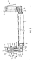
- FIG. 2 shows a view of the driven roller 7 along with a sectional illustration of the associated mounting of the roller 7.
- the roller 7 is rotatably received in the two bearing plates 5 arranged parallel to one another, with the aid of the bearing members 11.
- the bearing members 11 generally have a prismatic, elongated shape and are divided into an anchoring area 11a and a guide area 11b.
- the anchoring area 11a is fastened to the associated bearing plate 5 by means of two screws 18, the screws 18 being screwed into an anchor plate 19.
- guide sleeves 20 can be provided which are inserted into appropriately dimensioned bores 21 of the anchoring part 11a and of the bearing plates 5.
- the guide part 11b of the bearing members 11 engages over the opening 17 and is provided in the region of its free end with a respective bearing bush 22 which rotatably receives the shaft end 23 of the roller 7.
- one of the two shaft ends 23 has an extension 23a which receives a drive wheel 24 for driving the roller 7.
- the roller 7 is equipped with a gear 25 which meshes with a correspondingly arranged gear, not shown in FIG. 2, on the roller 8 and with a gear arranged on the roller 10, in order to drive it.
- the roller 8 is also with two projecting shaft ends 23 equipped, which are generally rotatably accommodated in two bearing members 12; the latter are anchored to the zugeord "Neten support plates 5 by means of screws 26th, the roller 8 carries a gear 27 which meshes with the gear 25 of the roller 7 so that the roller is set in rotation by the driven roller 7.
- the bearing member 12 comprises an anchoring part 12a, which is fastened to the bearing plate 5 by means of the screws 26, and a guide part 12b, which receives the shaft end 23.
- the latter is provided with a bearing bush 28 which is received in a bore 29 coaxial with the roller 8.
- a screw 31 is screwed into a threaded bore 30, which runs perpendicular to the bore 29, which extends through a longitudinal bore 32 in the anchoring part 12a of the bearing member 12 and which carries an adjusting knob 33 at its upper end.
- a locking sleeve 34 designed as a counter nut and screwed onto the spindle 31 is releasably clamped against the guide part 12b.
- a cylindrical extension 34a of the locking sleeve 34 is slidably received in the bore 32, it being possible, if necessary, to provide a bearing bush 35 for guiding said extension 34a without play.
- a part of the bore 32 in the anchoring part 12a is enlarged in diameter and accommodates a spring 36 which is supported on the one hand against the front end of the cylindrical extension 34a of the locking sleeve and on the other hand against the final end region 37 of the anchoring part 12a.
- the spring 36 thus strives to the locking sleeve 34 together with the spindle 31 and to push down attached guide member 12b. This displacement path is limited by the setting of the adjusting button 33 against the upper end face of the anchoring part 12a.
- a cranked lever 38 is inserted in the area of its shorter lever arm 38a under the adjusting knob 33, so that actuating the longer lever arm 38b can cause the adjusting knob 33 to be lifted off the anchoring part 12a, so that a spacer plate (not shown) can be inserted in between to adjust the radial one To change or adjust the position of the axis of the roller 8.
- the locking sleeve 34 is loosened somewhat, so that the spindle 31 can be removed from the threaded bore 30 of the guide part 12b by turning the adjusting knob 33. Now this guide part 12b can be pulled off the shaft end 23 and the roller 8 can be easily removed through the opening 17 in the axial direction.
- the assembly of a new roller 8 takes place in the corresponding reverse order, it being only necessary to adjust it by actuating the adjusting knob 33 by screwing the spindle 31 by the correct amount into the threaded bore 30 and then tightening the locking sleeve 34 again against the guide part 12b.
Landscapes
- Folding Of Thin Sheet-Like Materials, Special Discharging Devices, And Others (AREA)
- Auxiliary Devices For And Details Of Packaging Control (AREA)
Abstract
Description
Die vorliegende Erfindung bezieht sich auf eine Faltmaschine zum Falten von Bögen aus Papier oder papierähnlichem Blattmaterial.The present invention relates to a folding machine for folding sheets of paper or paper-like sheet material.
Im allgemeinen sind solche Maschinen mit einer Mehrzahl von Faltwalzen ausgerüstet, die jeweils paarweise funktionell einander zugeordnet sind, wobei pro Durchlauf des zu faltenden Bogens zwischen einem Walzenpaar ein Falz ausgebildet wird. Ueblicherweise bestehen diese Faltwalzen aus Stahl und weisen eine geriffelte oder anderweitig bearbeitete Oberfläche auf; gegebenenfalls können auch einzelne Oberflächenbereiche der Walzen durch Gummiauflagen oder dergleichen gebildet sein.In general, such machines are equipped with a plurality of folding rollers, each of which is functionally assigned to one another in pairs, a fold being formed between a pair of rollers per pass of the sheet to be folded. These folding rollers are usually made of steel and have a corrugated or otherwise machined surface; if necessary, individual surface areas of the rollers can also be formed by rubber pads or the like.
Die beiden Walzen eines zusammenarbeitenden Faltwalzen-Paares dürfen nicht starr zueinander angeordnet sein, weil eine solche Maschine in der Lage sein muss, Bögen aus Papier oder ähnlichem Blattmaterial in unterschiedlicher Blattstärke zu verarbeiten. Daraus leitet sich zum einen die Forderung ab, dass der gegenseitige Achsabstand eines Walzenpaares verstellbar sein muss, zwecks Anpassung an unterschiedliche Blattstärken. Zum anderen ist davon auszugehen, dass die Blattstärke in gewissen Grenzen variieren kann, dass Unregelmässigkeiten, z.B. Einschlüsse oder dergleichen im Blattmaterial, vorhanden sind, oder dass versehentlich einmal zwei oder mehr Blätter gleichzeitig zwischen die Walzen gelangen. Eine, wenn auch einstellbare, jedoch starre Lagerung der Walzen könnte zu unzulässig hohen Belastungen mit eventueller Zerstörung oder Beschädigung der Walzenlagerung führen, da Papier und ähnliches Blattmaterial bekannterweise sehr hart ist. Es ist deshalb erforderlich, zumindest eine der Walzen eines zusammenarbeitenden Walzenpaares in radialer Richtung nachgiebig zu lagern.The two rollers of a cooperating pair of folding rollers must not be arranged rigidly to one another, because such a machine must be able to process sheets of paper or similar sheet material with different sheet thicknesses. On the one hand, this leads to the requirement that the mutual center distance of a pair of rollers must be adjustable in order to adapt to different sheet thicknesses. On the other hand, it can be assumed that the sheet thickness can vary within certain limits, that irregularities, for example inclusions or the like, are present in the sheet material, or that it happens accidentally two or more sheets get between the rollers at the same time. An, albeit adjustable, but rigid bearing of the rollers could lead to impermissibly high loads with possible destruction or damage to the roller bearings, since paper and similar sheet material is known to be very hard. It is therefore necessary to resiliently mount at least one of the rollers of a cooperating pair of rollers in the radial direction.
All die zuvor genannten Forderungen zu erfüllen bedingt eine relativ aufwendige Konstruktion der Lagerung der Faltwalzen. Andererseits sind die einzelnen Walzen einer Abnutzung unterworfen und es ist nicht zu umgehen, die Walzen von Zeit zu Zeit auszuwechseln. Je komplizierter die Lagerung der Walzen ist, desto umständlicher und damit zeitraubender gestaltet sich deren Auswechslung.To meet all of the above requirements requires a relatively complex construction of the storage of the folding rollers. On the other hand, the individual rollers are subject to wear and it is inevitable to replace the rollers from time to time. The more complicated the storage of the rollers, the more cumbersome and therefore time-consuming they are to replace.
Bisher bekannte Faltmaschinen der eingangs erläuterten Art weisen im allgemeinen ein Maschinengestell auf, das zwei im Abstand zueinander angeordnete, parallelle Lagerungsplatten umfasst, zwischen welchen die Walzen an vorstehenden Wellenzapfen an den beiden Seiten gelagert sind. Diese Lagerplatten dienen dabei zugleich zur Aufnahme der erforderlichen Einstellorgane bzw. der federnden Abstützvorrichtung. Selbst um nur eine Walze auszuwechseln, ist es erforderlich, das gesamte Walzenaggregat zu demontieren bzw. zu zerlegen, d.h. die eine der Lagerplatten zu lösen und zu entfernen. Da eine solche Maschine üblicherweise mehrere Walzen umfasst, ist eine solche Demontage und insbesondere die nachfolgende Montage sowie Justierung der Walzen verhältnismässig kompliziert und somit zeitraubend. Das Auswechseln einer Walze oder mehrerer Walzen konnte bisher auch nur von qualifizierten Fachkräften vorgenommen werden, was sich insbesondere in Bezug auf die Höhe der Wartungskosten und den Zeitraum des Ausfalls der Maschine nachteilig ausgewirkt hat.Previously known folding machines of the type described in the introduction generally have a machine frame which comprises two parallel bearing plates which are arranged at a distance from one another and between which the rollers are mounted on projecting shaft journals on both sides. These bearing plates serve at the same time to accommodate the necessary adjusting elements or the resilient support device. Even in order to replace only one roller, it is necessary to dismantle or disassemble the entire roller assembly, ie to loosen and remove one of the bearing plates. Since such a machine usually comprises several rollers, such dismantling and in particular the subsequent assembly and adjustment of the rollers is proportionate complicated and therefore time consuming. Up to now, the replacement of one roller or several rollers could only be carried out by qualified specialists, which has had a disadvantageous effect, in particular with regard to the amount of maintenance costs and the period of machine failure.
Es ist die Aufgabe der vorliegenden Erfindung, diese Nachteile zu vermeiden und eine Faltmaschine vorzuschlagen, die sich insbesondere durch eine einfache, robuste Konstruktion auszeichnet und bei der einzelne Faltwalzen auf einfachste und zeitsparendste Weise, selbst von unausgebildetem Personal, ausgewechselt werden können.It is the object of the present invention to avoid these disadvantages and to propose a folding machine which is characterized in particular by a simple, robust construction and in which individual folding rollers can be replaced in the simplest and most time-saving manner, even by untrained personnel.
Die Erfindung geht aus von einer Faltmaschine zum Falten von Bögen aus Papier oder papierähnlichem Blattmaterial, mit einer Mehrzahl von Faltwalzen,' die endseitig in einem Maschinengestell drehbar gelagert sind, wobei jeweils zumindest eine Walze eines Faltwalzenpaares gegenüber der zugeordneten, zweiten Walze des Paares bezüglich des Drehachsenabstandes verschiebbar und einstellbar ist.The invention is based on a folding machine for folding sheets of paper or paper-like sheet material, with a plurality of folding rollers, which are rotatably supported at the ends in a machine frame, at least one roller of a pair of folding rollers opposite the associated second roller of the pair with respect to the Axis distance is slidable and adjustable.
Um die erfindungsgemässe Aufgabe zu lösen, zeichnet sich eine solche Faltmaschine dadurch aus, dass das Maschinengestell mindestens einseitig im Bereich der benachbarten Stirnseite jeder Walze mit einer Durchbrechung versehen ist, deren Grösse mindestens der gesamten axialen Seitenprojektionsfläche der betreffenden Mehrzahl von Walzen, gegebenenfalls einschliesslich zugeordneten Hilfselementen, entspricht, und dass die Lagerung jeder Walze zumindest einseitig mit Hilfe eines Lagergliedes erfolgt, welches am Maschinengestell lösbar befestigt ist und teilweise die Durchbrechung überragt.In order to achieve the object according to the invention, such a folding machine is characterized in that the machine frame is provided at least on one side in the area of the adjacent end face of each roller with an opening, the size of which is at least the entire axial side projection surface of the relevant plurality of rollers, possibly including associated auxiliary elements , corresponds, and that storage each roller is carried out at least on one side with the aid of a bearing member which is detachably attached to the machine frame and partially projects beyond the opening.
Dadurch kann ohne grossen konstruktiven Aufwand eine überzeugende Lösung realisiert werden, um eine Walze bei Bedarf auszuwechseln, indem lediglich das im Bereich der genannten Durchbrechung liegende Lagerglied vom Maschinengestell entfernt, die betreffende Walze herausgezogen, die neue Walze eingesetzt und das Lagerglied wieder am Maschinengestell befestigt wird. Die gesamten konstruktiven Massnahmen zur Einstellung des Lagerabstandes und gegebenenfalls zur federnden Abstützung können dabei innerhalb des Lagergliedes zusammengefasst sein und werden durch die Demontage des Lagergliedes bzw, die nachfolgende Montage nicht beeinflusst, sodass keine neuerliche Justierung oder zumindest nur in vermindertem Ausmas.s erforderlich sein wird.As a result, a convincing solution can be implemented without great design effort, in order to replace a roller if necessary, simply by removing the bearing element in the area of the opening mentioned, pulling out the roller in question, inserting the new roller and fastening the bearing element again to the machine frame . The entire constructional measures for adjusting the bearing distance and possibly for resilient support can be combined within the bearing member and are not affected by the dismantling of the bearing member or the subsequent assembly, so that no new adjustment or at least to a reduced extent will be necessary .
Je nach dem, ob es sich bei der Faltwalze um die Antriebswalze handelt, die von einem Elektromotor, z.B. über einen Riemen angetrieben wird und welche zum Beispiel mittels Zahnradkoppelung ihrerseits die restlichen Walzen antreibt, oder um eine von dieser Antriebswalze in Drehung versetzte Faltwalze, kann die Ausbildung des jeweiligen Lagergliedes unterschiedlich sein. Im allgemeinen ist es nämlich nicht erforderlich, die Antriebswalze einstellbar oder federnd abgestützt zu lagern, da diese innerhalb der Maschine die Bezugsachse festlegt. Es genügt somit, diese An triebswalze beidseitig mittels eines einstückigen Lagergliedes drehbar zu haltern, welches Lagerglied einen starr am Maschinengestell befestigten ersten Bereich und einen zweiten, die Durchbrechung überragenden, mit einer Lagerbüchse versehenen und das zugeordnete Wellenende der Walze aufnehmenden Bereich besitzt. Zur Auswechslung der Antriebswalze kann somit einfach das Lagerglied zu entfernen und die Walze, gegebenenfalls nach Lösen der Antriebsmittel, herauszuziehen.Depending on whether the folding roller is the drive roller, which is driven by an electric motor, e.g. via a belt, and which, for example, drives the remaining rollers by means of gear coupling, or a folding roller set in rotation by this drive roller the training of the respective bearing element may be different. In general, it is in fact not necessary to mount the drive roller in an adjustable or spring-supported manner, since this defines the reference axis within the machine. It is therefore sufficient to rotatably support this drive roller on both sides by means of a one-piece bearing member, which bearing member is rigidly attached to the machine frame-fastened first area and a second area, which projects beyond the opening, is provided with a bearing bush and receives the associated shaft end of the roller. To replace the drive roller, the bearing member can thus simply be removed and the roller pulled out, if necessary after loosening the drive means.
Zur Lagerung einer zum Beispiel dieser Antriebswalze zugeordneten, mit jener ein zusammenarbeitendes Walzenpaar bildenden Faltwalze wie auch der weiteren Faltwalzen kann es vorteilhaft sein, wenn das Lagerglied einen lösbar am Maschinengestell befestigten Verankerungsteil und einen das Wellenende der Walze aufnehmenden, die zugeordnete Durchbrechung übergreifenden Führungsteil umfasst. Zweckmässigerweise ist dabei der Führungsteil des Lagergliedes lösbar und bezüglich der Distanz einstellbar am Verankerungsteil des Lagergliedes befestigt. Diese Massnahme erlaubt es, zwecks Auswechslung der betreffenden Walze den Führungsteil vom Verankerungsteil zu lösen, ersteren vom Wellenende der Walze abzuziehen und die Walze in achsialer Richtung durch die Durchbrechung hindurch zu entfernen.For the storage of a folding roller assigned to this drive roller, for example, with the folding roller forming a cooperating pair of rollers as well as the other folding rollers, it can be advantageous if the bearing member comprises an anchoring part which is detachably fastened to the machine frame and a guide part which receives the shaft end of the roller and overlaps the assigned opening. The guide part of the bearing member is expediently detachable and adjustable in terms of distance to the anchoring part of the bearing member. This measure makes it possible to detach the guide part from the anchoring part for the purpose of replacing the roller in question, to pull the former away from the shaft end of the roller and to remove the roller in the axial direction through the opening.
Bei einer Maschine mit einer Mehrzahl von Faltwalzen, insbesondere wenn diese Walzen vergleichsweise nahe nebeneinander liegen, gestattet die erfindungsgemäss vorgesehene gemeinsame Durchbrechung, deren Grösse mindestens der gesamten achsialen Seitenprojektionsfläche der betreffenden Mehrzahl von Walzen entspricht, eine konstruktive Vereinfachung, wobei gleichzeitig sichergestellt ist, dass jede einzelne der Walzen, nach Entfernung des Führungsteils, durch diese gemeinsame Durchbrechung hindurch herausziehbar ist.In the case of a machine with a plurality of folding rollers, in particular if these rollers are comparatively close to one another, the shared opening provided according to the invention, the size of which corresponds at least to the entire axial side projection surface of the relevant plurality of rollers, allows a design simplification, while at the same time ensuring that each individual of the rollers, after removal of the Guide part, can be pulled out through this common opening.
Eine konstruktiv einfache, preisgünstig zu verwirklichende und dabei gleichzeitig robuste Ausführung des Lagergliedes kann darin erblickt werden, dass der Führungsteil mit einer Lagerbohrung versehen ist, die eine das Wellenende der zugehörigen Walze aufnehmende Lagerbüchse aufweist. Zur Befestigung dieses Führungsteiles am Verankerungsteil ist zweckmässigerweise eine Spindel vorgesehen, welche einerends im Führungsteil in einer senkrecht zur Lagerbohrung verlaufenden Gewindebohrung lösbar aufgenommen ist, welche Spindel sich ferner durch eine zentrale Bohrung im Verankerungsteil hindurch erstreckt und welche andernends einen Betätigungsknopf trägt.A structurally simple, inexpensive to implement and at the same time robust design of the bearing member can be seen in the fact that the guide part is provided with a bearing bore which has a bearing bush which receives the shaft end of the associated roller. For fastening this guide part to the anchoring part, a spindle is expediently provided, which is detachably received at one end in the guide part in a threaded bore running perpendicular to the bearing bore, which spindle also extends through a central bore in the anchoring part and which at the other end carries an actuating button.
Zur Sicherung der federnden Abstützung kann die zentrale Bohrung im Verankerungsteil zumindest teilweise grösseren Durchmesser als die genannte Spindel besitzen und eine Feder aufnehmen, die sich gegen eine führungsteilseitig in das Ende der zentralen Bohrung verschiebbar eingesetzte, auf die Spindel aufgeschraubte Arretierhülse abstützt.To secure the resilient support, the central bore in the anchoring part can at least partially have a larger diameter than the mentioned spindle and can accommodate a spring which is supported against a locking sleeve which is slidably inserted into the end of the central bore and is screwed onto the spindle.
Wenn zwischen der Auflagefläche des Betätigungsknopfes und der zugewandten Stirnseite des Verankerungsteiles des Lagergliedes ein abgekröpfter Betätigungshebel eingesetzt ist, kann die zugeordnete Walze auf einfachste Weise bezüglich des Achsabstandes der anderen Walze dieses Walzenpaares durch achsiale Verschiebung der Spindel verschoben werden, wobei gegebenenfalls geeignete Distanzstücke zwischen Betätigungshebel und Stirnseite des Verankerungsteiles eingesetzt werden können, um den Achsabstand auf ein vorbestimmtes Mass zu fixieren.If an angled actuating lever is inserted between the contact surface of the actuating button and the facing end face of the anchoring part of the bearing member, the associated roller can be displaced in the simplest manner with respect to the center distance of the other roller of this pair of rollers by axial displacement of the spindle, where appropriate suitable Spacers can be used between the operating lever and the front side of the anchoring part in order to fix the center distance to a predetermined dimension.
Im folgenden wird ein Ausführungsbeispiel des Erfindungsgegenstandes, unter Bezugnahme auf die beiliegenden Zeichnungen, näher erläutert. In den Zeichnungen zeigen:
- Fig. 1 eine schematische Teil-Seitenansicht eines Ausführungsbeispiels einer-Faltmaschine mit entfernter Seitenabdeckung,
- Fig. 2 eine Ansicht der Antriebswalze mit zugehöriger Lagerung im Schnitt, und
- Fig. 3 eine Ansicht einer der Faltwalzen mit zugehöriger Lagerung im Schnitt.
- 1 is a schematic partial side view of an embodiment of a folding machine with the side cover removed,
- Fig. 2 is a view of the drive roller with associated storage in section, and
- Fig. 3 is a view of one of the folding rollers with associated storage in section.
Aus der Fig. 1 ist eine schematische Seitenansicht des Walzenaggregates, generell mit 1 bezeichnet, dargestellt, zusammen mit dem Zufuhrtisch 2 für zu faltende Bogen aus Papier oder dergleichen, mit einer ersten Falttasche 3 und einer zweiten Falttasche 4. Das Walzenaggregat 1 weist zwei seitliche Lagerplatten 5 auf, von denen aus Fig. 1 nur die eine ersichtlich ist. Die zweite Lagerplatte 5 ist parallel dazu in einem im wesentlichen der Walzenbreite entsprechenden Abstand angeordnet und mittels nicht näher dargestellter Verbindungsstreben, die mit einer Anzahl von Schrauben 6 an den Lagerplatten 5 verankert sind, mit der ersten Lagerplatte 5 starr verbunden. Der Zufuhrtisch 2, die erste Falttasche 3 und die zweite Falttasche 4 sind ebenfalls durch nicht näher dargestellte Mittel an den beiden Lagerplatten 5 befestigt.1 shows a schematic side view of the roller assembly, generally designated 1, together with the feed table 2 for sheets of paper or the like to be folded, with a
Das Walzenaggregat 1 umfasst ausserdem eine Mehrzahl von Faltwalzen, im vorliegenden Ausführungsbeispiel vier an der Zahl, näm-lieh eine angetriebene Faltwalze 7 sowie drei weitere Faltwalzen 8, 9 und 10. Durch diese vier Faltwalzen sind drei funktionell einander zugeordnete Faltwalzen-Paare gebildet, wie nachstehend noch erläutert werden wird. Die angetriebene Faltwalze 7 ist mittels eines Lagergliedes 1'1 an der Lagerplatte 5 drehbar verankert, während die Faltwalze 8 mittels eines Lagergliedes 12, die Faltwalzen 9 mittels eines Lagergliedes 13 und die Faltwalze 10 mittels eines Lagergliedes 14 drehbar an der Lagerplatte 5 gelagert ist. Es versteht sich von selbst, dass bei der zuvor erwähnten, zweiten Lagerplatte-5 eine identische Anordnung vorgesehen sein kann, bzw. mit Vorteil vorgesehen ist.The
Obwohl die generelle Funktionsweise einer solchen Faltmaschine vorausgesetzt wird, soll an dieser Stelle kurz darauf eingegangen werden. Ein zu faltendes Blatt wird über den Zufuhrtisch 2 zwischen die Walzen 8 und 9 auf nicht näher dargestellte Weise eingeführt; die beiden Walzen 8 und 9 bilden somit ein erstes funktionelles Paar. Die vorlaufende Kante des Blattes gelangt in die erste Falttasche 3 hinein und wird gegen den darin verstellbar angeordneten Anschlag 15 anstossen. Im dynamischen Betrieb gelangt derjenige Bereich des Blattes, der sich im Zeitpunkt des Anstossens der vorlaufenden Kante an den Anschlag 15 oberhalb der beiden Walzen 7 und 8 befindet, zwischen dieselben, sodass durch diese beiden Walzen 7 und 8 der erste Falz ausgebildet wird; diese beiden Walzen stellen damit ein zweites, funktionelles Walzenpaar dar.Although the general functioning of such a folding machine is assumed, it will be briefly discussed here. A sheet to be folded is inserted through the feed table 2 between the
Das gefaltete Blatt wird nun durch die Walzen 7 und 8 weitergefördert und gelangt nun mit der Faltkante voran in die zweite Falttasche 4 hinein, bis die zuvor ausgebildete Faltkante gegen den ebenfalls verstellbar angeordneten Anschlag 16 anstösst. Der in diesem Moment im Bereich der Walzen 7 und 10 befindliche Blattabschnitt wird durch diese Walzen erfasst, sodass der zweite Falz ausgebildet wird, währenddem das Blatt zwischen diesen beiden Walzen 7 und 10 hindurchläuft; diese beiden letzteren bilden somit das dritte, funktionelle Walzenpaar. Schliesslich wird das auf diese Weise zweimal gefaltete Blatt hinter den Walzen 7 und 10 ausgestossen.The folded sheet is now conveyed further by the
Wie schon eingangs der Beschreibung erwähnt, ist es einerseits erforderlich, den gegenseitigen Achsabstand innerhalb eines funktionell zusammenarbeitenden Walzenpaares auf ein ganz bestimmtes Mass einzustellen und andererseits, mindestens die eine Walze innerhalb eines funktionell zusammenarbeitenden Walzenpaares federnd in radialer Richtung nachgiebig zu lagern. Im vorliegenden Ausführungsbeispiel ist die durch nicht näher dargestellte Mittel, z.B. von einem Elektromotor über einen Riemen, angetriebene Walze 7 starr gelagert, und zwar mittels der beidseitig angeordneten Lagerglieder 11. Auf die Konstruktion derselben wird im einzelnen noch näher eingegangen werden. Die restlichen Walzen, nämlich die Walzen 8, 9 und 10, sind je mittels zweier Lagerglieder 12, 13 und 14 drehbar gehaltert, wobei diese erwähnten Lagerglieder einen fest an den Lagerplatten 5 angebrachten Verankerungsteil 12a, 13a, 14a, sowie einen gegenüber den Verankerungsteilen verschiebbaren, bezüglich des Abstandes einstellbaren, sowie federnd abgestützten Führungsteil 12b, 13b, 14b umfassen. Auch auf die nähere Ausbildung der zuletzt erwähnten Lagerglieder sowie deren Komponenten wird anschliessend noch näher eingegangen werden.As already mentioned at the beginning of the description, it is necessary, on the one hand, to set the mutual center distance within a functionally cooperating pair of rollers to a specific degree and, on the other hand, to resiliently resiliently mount at least one roller within a functionally cooperating pair of rollers in the radial direction. In the present exemplary embodiment, the
Wesentlich in diesem Zusammenhang ist zunächst, dass die Lagerplatten 5 mit einer Durchbrechung 17 versehen sind, entlang deren Randes die einzelnen Lagerglieder 11 sowie 12 bis 14 befestigt sind. Im vorliegenden Ausführungsbeispiel ist pro Lagerplatte 5 eine einzige Durchbrechung 17 vorgesehen, deren Grösse so bemessen ist, dass sie die achsiale Seitenprojektion sämtlicher Walzen 7 bis 10, inklusive vorhandener Hilfselemente wie z.B. Zahnräder zur gegenseitigen Antriebskoppelung der einzelnen Walzen, umfasst. Dabei ist nur ein Bereich der Lagerglieder an den Lagerplatten 5 befestigt, während ein weiterer Bereich derselben die Durchbrechung 17 überragt. Im Fall des Lagergliedes 11 ist ein Verankerungsteil 11a mit den Lagerplatten 5 verbunden, währenddem ein Bereich 11b die Durchbrechung 17 überragt und die Walze 7 abstützt. Im Fall der Lagerglieder 12, 13 und 14 ist der Verankerungsteil 12a, 13a und 14a an den Lagerplatten 5 befestigt, während jeweils der Führungsteil 12b, 13b und 14b die Durchbrechung 17 überragt und die jeweils zugeordneten Walzen 8, 9 und 10 drehbar aufnimmt.It is essential in this context that the
Durch diese erfindungsgemäss vorgeschlagene Konstruktion ist es ersichtlicherweise leicht möglich, einzelne Walzen auszuwechseln, indem einseitig das zugeordnete Lagerglied bzw. ein Teil desselben entfernt wird, sodass die betreffende Walze durch die Durchbrechung hindurch herausgezogen werden kann. Somit ist es ermöglicht, ohne Demontage des gesamten Walzenaggregates Zugang zu jeder einzelnen Walze zu erhalten. Dadurch, dass die gesamte Ei'n- stellvorrichtung und die Elemente für die federnde Abstützung der Walzen in den betreffenden Lagergliedern 12, 13 und 14 integriert sind, wie nachstehend noch erläutert werden wird, vereinfacht sich ein Walzenwechsel weiter und enthebt die Bedienungsperson der Notwendigkeit, nach dem Auswechseln, z.B. nur einer einzigen Walze, das gesamte Walzenaggregat neu justieren zu müssen.By means of this construction proposed according to the invention, it is evidently possible to replace individual rollers by removing the associated bearing member or a part thereof on one side, so that the roller in question can be pulled out through the opening. This makes it possible to get access to each individual roller without dismantling the entire roller unit. Characterized in that the whole egg n '- actuating device and the elements for the resilient support of the rollers in the
Aus der Fig. 2 ist eine Ansicht der angetriebenen Walze 7 nebst einer geschnittenen Darstellung der zugehörigen Lagerung der Walze 7 zu entnehmen. Die Walze 7 ist, wie zuvor schon erwähnt, in den beiden parallel zueinander angeordneten Lagerplatten 5 drehbar aufgenommen, und zwar mit Hilfe der Lagerglieder 11. Die Lagerglieder 11 besitzen generell prismatische, längliche Gestalt und sind unterteilt in einen Verankerungsbereich 11a sowie einen Führungsbereich 11b. Der Verankerungsbereich 11a ist mittels zweier Schrauben 18 an der zugehörigen Lagerplatte 5 befestigt, wobei die Schrauben 18 in eine Ankerplatte 19 eingeschraubt sind. Zur präzisen Lagebestimmung können Führungshülsen 20 vorgesehen sein, die in entsprechend bemessene Bohrungen 21 des Verankerungsteiles 11a sowie der Lagerplatten 5 eingesetzt sind.FIG. 2 shows a view of the driven
Der Führungsteil 11b der Lagerglieder 11 übergreift die Durchbrechung 17 und ist im Bereich seines freien Endes mit je einer Lagerbüchse 22 versehen, welche das Wellenende 23 der Walze 7 drehbar aufnimmt. Im Fall der angetriebenen Walze 7 besitzt das eine der beiden Wellenenden 23 einen Fortsatz 23a, welcher ein Antriebsrad 24 zum Antrieb der Walze 7 aufnimmt. Weiter ist die Walze 7 mit einem Zahnrad 25 ausgerüstet, welches mit einem entsprechend angeordneten, aus Fig. 2 nicht ersichtlichen, Zahnrad auf der Walze 8 sowie mit einem auf der Walze 10 angeordneten Zahnrad kämmt, um diese ihrerseits anzutreiben.The
Aus der Fig. 2 wie auch aus den vorstehenden Erläuterungen kann leicht erkannt werden, dass zur Auswechslung der Walze 7 lediglich das Antriebsrad 24 und anschliessend das linksseitige Lagerglied 11 durch Lösen der Schrauben 18 entfernt werden muss, um die gesamte Walze 7 durch die Durchbrechung 17 hindurch aus dem Walzenaggregat 1 hinauszuziehen. Bei der Montage der neuen Walze 7 wird sinngemäss umgekehrt vorgegangen, wobei die Führungshülsen 20 für einen passgenauen Sitz des Lagergliedes 11 sorgen.From FIG. 2 as well as from the above explanations, it can easily be seen that in order to replace the
In der Fig. 3 ist eine von der Walze 7 angetriebene Walze, z.B. die Faltwalze 8, in einer Ansicht mit der zugehörigen Lagerung im Schnitt dargestellt. Es versteht sich von selbst, dass, obwohl im folgenden nur auf die Lagerung der Walze 8 Bezug genommen wird, entsprechendes sinngemäss für die Faltwalzen 9 und 10 und deren Lagerung gilt.In Fig. 3 a roller driven by the
Die Walze 8 ist ebenfalls mit zwei vorstehenden Wellenenden 23 ausgerüstet, die generell in zwei Lagergliedern 12 drehbar Aufnahme finden; letztere sind mittels Schrauben 26 an den zugeord" neten Lagerplatten 5 verankert. Die Walze 8 trägt ein Zahnrad 27, welches mit dem Zahnrad 25 der Walze 7 kämmt, sodass die Walze 8 durch die angetriebene Walze 7 in Rotation versetzt wird.The
Wie schon zuvor erwähnt, umfasst das Lagerglied 12 einen Verankerungsteil 12a, der mittels der Schrauben 26 an der Lagerplatte 5 befestigt ist, sowie einen Führungsteil 12b, der das Wellenende 23 aufnimmt. Zu diesem Zwecke ist letzterer mit einer Lagerbüchse 28 versehen, die in einer zur Walze 8 koachsialen Bohrung 29 Aufnahme findet. In eine Gewindebohrung 30, die senkrecht zur Bohrung 29 verläuft, ist eine Spindel 31 eingeschraubt, welche sich durch eine Längsbohrung 32 im Verankerungsteil 12a des Lagergliedes 12 hindurch erstreckt und welche an ihrem oberen Ende einen Einstellknopf 33 trägt. Eine als Kontermutter ausgebildete, auf die Spindel 31 aufgeschraubte Arretierhülse 34 ist gegen den Führungsteil 12b lösbar verspannt. Ein zylindrischer Fortsatz 34a der Arretierhülse 34 ist gleitend in der Bohrung 32 aufgenommen, wobei gegebenenfalls eine Lagerbüchse 35 zur spielfreien Führung des genannten Fortsatzes 34a vorgesehen sein kann.As already mentioned above, the bearing
Ein Teil der Bohrung 32 im Verankerungsteil 12a ist im Durchmesser vergrössert und nimmt eine Feder 36 auf, die sich einerseits gegen das stirnseitige Ende des zylindrischen Fortsatzes 34a der Arretierhülse und andererseits gegen den abschliessenden Endbereich 37 des Verankerungsteiles 12a abstützt. Die Feder 36 hat somit das Bestreben, die Arretierhülse 34 samt Spindel 31 und daran befestigtem Führungsteil 12b nach unten zu drücken. Dieser Verschiebeweg wird durch die Anlage des Einstellknopfes 33 gegen die obere Stirnfläche des Verankerungsteiles 12a begrenzt.A part of the
Ein abgekröpfter Hebel 38 ist im Bereich seines kürzeren Hebelarmes 38a unter den Einstellknopf 33 eingefügt, sodass durch Betätigung des längeren Hebelarmes 38b ein Abheben des Einstellknopfes 33 vom Verankerungsteil 12a bewirkt werden kann, sodass dazwischen ein (nicht dargestelltes) Distanzplättchen einsetzbar ist, um die radiale Lage der Achse der Walze 8 zu verändern bzw. einzustellen.A cranked
Zum Auswechseln der Walze 8 wird die Arretierhülse 34 etwas gelöst, sodass durch Drehen des Einstellknopfes 33 die Spindel 31 aus der Gewindebohrung 30 des Führungsteiles 12b entfernt werden kann. Nun lässt sich dieser Führungsteil 12b vom Wellenende 23 abziehen und die Walze 8 kann mühelos durch die Durchbrechung 17 hindurch in achsialer Richtung entfernt werden. Die Montage einer neuen Walze 8 geschieht in entsprechend umgekehrter Reihenfolge, wobei es zur Justierung derselben lediglich erforderlich ist, durch Betätigung des Einstellknopfes 33 die Spindel 31 um das richtige Mass in die Gewindebohrung 30 einzuschrauben und anschliessend die Arretierhülse 34 wieder gegen den Führungsteil 12b anzuziehen.To replace the
Es versteht sich, dass im Rahmen des Erfindungsgedankens zahlreiche Variationen möglich sind. Wesentlich ist, dass die die Walzenenden tragenden Lagerelemente, die die Durchbrechung übergreifen, leicht entfernbar sind, um die entsprechende Walze ohne Demontage des gesamten Walzenaggregates auswechseln zu können. Es ist natürlich auch möglich, für jede Walze gesondert eine entsprechend bemessene Durchbrechung vorzusehen, falls dies konstruktiv vorteilhafter sein sollte. Unter Umständen kann es gegenügen, lediglich die eine Lagerplatte 5 mit Durchbrechungen zu versehen, die ein Entfernen der Walzen nur von der einen Seite her gestatten.It goes without saying that numerous variations are possible within the scope of the inventive concept. It is essential that the bearing elements supporting the roller ends overlap the opening fen, are easy to remove in order to be able to replace the corresponding roller without dismantling the entire roller unit. It is of course also possible to provide a correspondingly dimensioned opening for each roller, should this be structurally advantageous. Under certain circumstances, it may be sufficient to provide only the one
Claims (8)
Priority Applications (1)
| Application Number | Priority Date | Filing Date | Title |
|---|---|---|---|
| AT85109545T ATE33972T1 (en) | 1984-08-01 | 1985-07-30 | FOLDING MACHINE. |
Applications Claiming Priority (2)
| Application Number | Priority Date | Filing Date | Title |
|---|---|---|---|
| DE3428308 | 1984-08-01 | ||
| DE3428308 | 1984-08-01 |
Publications (2)
| Publication Number | Publication Date |
|---|---|
| EP0170251A1 true EP0170251A1 (en) | 1986-02-05 |
| EP0170251B1 EP0170251B1 (en) | 1988-05-04 |
Family
ID=6242077
Family Applications (1)
| Application Number | Title | Priority Date | Filing Date |
|---|---|---|---|
| EP85109545A Expired EP0170251B1 (en) | 1984-08-01 | 1985-07-30 | Folding machine |
Country Status (3)
| Country | Link |
|---|---|
| EP (1) | EP0170251B1 (en) |
| AT (1) | ATE33972T1 (en) |
| DE (1) | DE3562476D1 (en) |
Cited By (2)
| Publication number | Priority date | Publication date | Assignee | Title |
|---|---|---|---|---|
| EP1132327A2 (en) * | 2000-03-09 | 2001-09-12 | Heidelberger Druckmaschinen Aktiengesellschaft | Drive for a first and a second folding roller |
| WO2012072416A1 (en) * | 2010-11-30 | 2012-06-07 | Oce-Technologies B.V. | Sheet folding apparatus, sheet folding method, and printing system including the sheet folding apparatus |
Citations (3)
| Publication number | Priority date | Publication date | Assignee | Title |
|---|---|---|---|---|
| US4032133A (en) * | 1975-09-11 | 1977-06-28 | Steffens Charles J | Roller positioning method and apparatus for buckle-type paper folding machine |
| GB2106478A (en) * | 1981-09-21 | 1983-04-13 | Polygraph Leipzig | Sheet folding apparatus |
| CH636321A5 (en) * | 1978-01-04 | 1983-05-31 | Vittorio Vigano | FOLDING MACHINE FOR FOLDING FILMS OR SHEETS. |
-
1985
- 1985-07-30 EP EP85109545A patent/EP0170251B1/en not_active Expired
- 1985-07-30 DE DE8585109545T patent/DE3562476D1/en not_active Expired
- 1985-07-30 AT AT85109545T patent/ATE33972T1/en active
Patent Citations (3)
| Publication number | Priority date | Publication date | Assignee | Title |
|---|---|---|---|---|
| US4032133A (en) * | 1975-09-11 | 1977-06-28 | Steffens Charles J | Roller positioning method and apparatus for buckle-type paper folding machine |
| CH636321A5 (en) * | 1978-01-04 | 1983-05-31 | Vittorio Vigano | FOLDING MACHINE FOR FOLDING FILMS OR SHEETS. |
| GB2106478A (en) * | 1981-09-21 | 1983-04-13 | Polygraph Leipzig | Sheet folding apparatus |
Cited By (5)
| Publication number | Priority date | Publication date | Assignee | Title |
|---|---|---|---|---|
| EP1132327A2 (en) * | 2000-03-09 | 2001-09-12 | Heidelberger Druckmaschinen Aktiengesellschaft | Drive for a first and a second folding roller |
| EP1132327A3 (en) * | 2000-03-09 | 2003-04-02 | Heidelberger Druckmaschinen Aktiengesellschaft | Drive for a first and a second folding roller |
| US6655276B1 (en) | 2000-03-09 | 2003-12-02 | Heidelberger Druckmaschinen Ag | Device for driving folding rolls |
| WO2012072416A1 (en) * | 2010-11-30 | 2012-06-07 | Oce-Technologies B.V. | Sheet folding apparatus, sheet folding method, and printing system including the sheet folding apparatus |
| US9486973B2 (en) | 2010-11-30 | 2016-11-08 | Oce Technologies B.V. | Sheet folding apparatus, sheet folding method, and printing system including the sheet folding apparatus |
Also Published As
| Publication number | Publication date |
|---|---|
| DE3562476D1 (en) | 1988-06-09 |
| ATE33972T1 (en) | 1988-05-15 |
| EP0170251B1 (en) | 1988-05-04 |
Similar Documents
| Publication | Publication Date | Title |
|---|---|---|
| DE69411964T2 (en) | Bearingless die rolls and machine housings | |
| DE7712968U1 (en) | ROTARY PRINTING MACHINE | |
| EP0182156A2 (en) | Offset-printing machine | |
| DE2448814B2 (en) | DEVICE FOR THE PUNCHING PRESSURE REGULATION OF A CRUCIBLE PUNCHING PRESS AND FOR ADJUSTING THE CRUCIBLES TO ONE Another | |
| DE3412606A1 (en) | SUSPENSION FOLDING MACHINE WITH PROTECTIVE HOUSING | |
| EP0769373A1 (en) | Device for changing printing-cylinder-sleeves of printing machines | |
| CH632956A5 (en) | Adjuster COLOR KNIFE A PRINTING MACHINE. | |
| DE2555604B2 (en) | DEVICE FOR ADJUSTING THE CONTINUOUS RUNNING OF THE ROLLER PROFILES OF A PAIR OF TOOL ROLLERS ON A WEDGE CROSS ROLLING MACHINE | |
| DE2415836B2 (en) | Device for defining the nips when separating the rolls of a calender | |
| EP0170251B1 (en) | Folding machine | |
| EP0429808B1 (en) | Device for precisely registering and tensioning a printing plate upon an impression cylinder | |
| DD266233A3 (en) | DEVICE FOR FIXING A BENDING PRESSURE PLATE | |
| DE1602184B2 (en) | Multi-roll stand arrangement | |
| DE2807183C3 (en) | Machine for cutting wire ends on assembled circuit boards | |
| DE19712774C2 (en) | Drive assembly of a shearer loader | |
| DE3324445A1 (en) | COLOR DOSING DEVICE ON BOOK AND OFFSET PRINTING MACHINES | |
| EP0121921B1 (en) | Tensioning device for a belt-shaped conveyor element | |
| DE2850397C2 (en) | Straightening machine for profile steel | |
| DE10035001B4 (en) | guide roll | |
| DE2656773C2 (en) | Device for changing the distance between two opposing support or guide rollers in a continuous caster | |
| DE8422842U1 (en) | Folding machine | |
| DE69210572T2 (en) | Quick-change cutting shear device for a machine for molding glass objects | |
| EP0374588A1 (en) | Rotary mower | |
| DE10253345B4 (en) | Device for facilitating hammer mill maintenance | |
| CH390287A (en) | Device for setting the folding rollers of paper folding machines |
Legal Events
| Date | Code | Title | Description |
|---|---|---|---|
| PUAI | Public reference made under article 153(3) epc to a published international application that has entered the european phase |
Free format text: ORIGINAL CODE: 0009012 |
|
| AK | Designated contracting states |
Designated state(s): AT BE CH DE FR GB IT LI LU NL SE |
|
| 17P | Request for examination filed |
Effective date: 19860728 |
|
| 17Q | First examination report despatched |
Effective date: 19870206 |
|
| ITF | It: translation for a ep patent filed | ||
| GRAA | (expected) grant |
Free format text: ORIGINAL CODE: 0009210 |
|
| AK | Designated contracting states |
Kind code of ref document: B1 Designated state(s): AT BE CH DE FR GB IT LI LU NL SE |
|
| REF | Corresponds to: |
Ref document number: 33972 Country of ref document: AT Date of ref document: 19880515 Kind code of ref document: T |
|
| RAP4 | Party data changed (patent owner data changed or rights of a patent transferred) |
Owner name: MULTIGRAF AG |
|
| GBT | Gb: translation of ep patent filed (gb section 77(6)(a)/1977) | ||
| REF | Corresponds to: |
Ref document number: 3562476 Country of ref document: DE Date of ref document: 19880609 |
|
| ET | Fr: translation filed | ||
| PLBE | No opposition filed within time limit |
Free format text: ORIGINAL CODE: 0009261 |
|
| STAA | Information on the status of an ep patent application or granted ep patent |
Free format text: STATUS: NO OPPOSITION FILED WITHIN TIME LIMIT |
|
| 26N | No opposition filed | ||
| ITTA | It: last paid annual fee | ||
| PGFP | Annual fee paid to national office [announced via postgrant information from national office to epo] |
Ref country code: AT Payment date: 19940614 Year of fee payment: 10 |
|
| PGFP | Annual fee paid to national office [announced via postgrant information from national office to epo] |
Ref country code: BE Payment date: 19940620 Year of fee payment: 10 |
|
| PGFP | Annual fee paid to national office [announced via postgrant information from national office to epo] |
Ref country code: LU Payment date: 19940630 Year of fee payment: 10 |
|
| EPTA | Lu: last paid annual fee | ||
| PGFP | Annual fee paid to national office [announced via postgrant information from national office to epo] |
Ref country code: NL Payment date: 19940731 Year of fee payment: 10 |
|
| EAL | Se: european patent in force in sweden |
Ref document number: 85109545.5 |
|
| PG25 | Lapsed in a contracting state [announced via postgrant information from national office to epo] |
Ref country code: LU Free format text: LAPSE BECAUSE OF NON-PAYMENT OF DUE FEES Effective date: 19950730 Ref country code: AT Effective date: 19950730 |
|
| PG25 | Lapsed in a contracting state [announced via postgrant information from national office to epo] |
Ref country code: BE Effective date: 19950731 |
|
| BERE | Be: lapsed |
Owner name: MULTIGRAF A.G. Effective date: 19950731 |
|
| PG25 | Lapsed in a contracting state [announced via postgrant information from national office to epo] |
Ref country code: NL Effective date: 19960201 |
|
| NLV4 | Nl: lapsed or anulled due to non-payment of the annual fee |
Effective date: 19960201 |
|
| REG | Reference to a national code |
Ref country code: GB Ref legal event code: IF02 |
|
| PGFP | Annual fee paid to national office [announced via postgrant information from national office to epo] |
Ref country code: SE Payment date: 20020617 Year of fee payment: 18 |
|
| PG25 | Lapsed in a contracting state [announced via postgrant information from national office to epo] |
Ref country code: SE Free format text: LAPSE BECAUSE OF NON-PAYMENT OF DUE FEES Effective date: 20030731 |
|
| EUG | Se: european patent has lapsed | ||
| PGFP | Annual fee paid to national office [announced via postgrant information from national office to epo] |
Ref country code: FR Payment date: 20040913 Year of fee payment: 20 |
|
| PGFP | Annual fee paid to national office [announced via postgrant information from national office to epo] |
Ref country code: GB Payment date: 20040916 Year of fee payment: 20 |
|
| PGFP | Annual fee paid to national office [announced via postgrant information from national office to epo] |
Ref country code: DE Payment date: 20040917 Year of fee payment: 20 Ref country code: CH Payment date: 20040917 Year of fee payment: 20 |
|
| PG25 | Lapsed in a contracting state [announced via postgrant information from national office to epo] |
Ref country code: GB Free format text: LAPSE BECAUSE OF EXPIRATION OF PROTECTION Effective date: 20050729 |
|
| REG | Reference to a national code |
Ref country code: GB Ref legal event code: PE20 |
|
| REG | Reference to a national code |
Ref country code: CH Ref legal event code: PL |