EP0170086A2 - Device for mounting a roof lining, apart from other parts, from the interior of a vehicle body of a motor vehicle, especially a passenger car - Google Patents
Device for mounting a roof lining, apart from other parts, from the interior of a vehicle body of a motor vehicle, especially a passenger car Download PDFInfo
- Publication number
- EP0170086A2 EP0170086A2 EP85108227A EP85108227A EP0170086A2 EP 0170086 A2 EP0170086 A2 EP 0170086A2 EP 85108227 A EP85108227 A EP 85108227A EP 85108227 A EP85108227 A EP 85108227A EP 0170086 A2 EP0170086 A2 EP 0170086A2
- Authority
- EP
- European Patent Office
- Prior art keywords
- assembly
- parts
- roof
- frame
- mounting
- Prior art date
- Legal status (The legal status is an assumption and is not a legal conclusion. Google has not performed a legal analysis and makes no representation as to the accuracy of the status listed.)
- Granted
Links
Images

Classifications
-
- B—PERFORMING OPERATIONS; TRANSPORTING
- B60—VEHICLES IN GENERAL
- B60R—VEHICLES, VEHICLE FITTINGS, OR VEHICLE PARTS, NOT OTHERWISE PROVIDED FOR
- B60R13/00—Elements for body-finishing, identifying, or decorating; Arrangements or adaptations for advertising purposes
- B60R13/02—Internal Trim mouldings ; Internal Ledges; Wall liners for passenger compartments; Roof liners
- B60R13/0212—Roof or head liners
- B60R13/0225—Roof or head liners self supporting head liners
-
- B—PERFORMING OPERATIONS; TRANSPORTING
- B62—LAND VEHICLES FOR TRAVELLING OTHERWISE THAN ON RAILS
- B62D—MOTOR VEHICLES; TRAILERS
- B62D65/00—Designing, manufacturing, e.g. assembling, facilitating disassembly, or structurally modifying motor vehicles or trailers, not otherwise provided for
- B62D65/02—Joining sub-units or components to, or positioning sub-units or components with respect to, body shell or other sub-units or components
- B62D65/14—Joining sub-units or components to, or positioning sub-units or components with respect to, body shell or other sub-units or components the sub-units or components being passenger compartment fittings, e.g. seats, linings, trim, instrument panels
Definitions
- the invention relates to a method for installing a headliner, in addition to other parts to be fastened from the inside to the roof, such as sun visors, grab handles and the like, in a body of motor vehicles, in particular passenger cars.
- the object of the invention is to take measures so that the parts in question can be assembled more easily, quickly and at lower cost.
- the object is achieved in that the headliner and the other parts are preassembled on a mounting frame in the stand next to the final assembly line to form an assembly unit, and in that the assembly unit then into the body through a window opening, preferably through the front or rear window or tailgate opening retracted, raised to the roof frame height and through the window and / or door openings - sideways and / or lengthways in Mon day position is clawed to the body and that then the final assembly of the parts located on the assembly unit is carried out on the body and that then the claw is released, the mounting frame is lowered and finally moved out of the body.
- the invention advantageously permits extensive automation of the assembly of the roof lining, along with the individual parts located in this area, within the motor vehicle body.
- the parts can be pre-assembled on the assembly frame by hand or automatically.
- a device for performing the method is characterized by an assembly frame with receiving and releasing devices for the parts to be installed in the body, such that the parts can be preassembled on the assembly frame in accordance with their later final assembly position, and further in that the mounting frame has hook-like movable holding elements on at least two opposite side edges, preferably on all side edges, which at the same time serve as a centering device for the mounting unit on the roof inside the body.
- the assembly frame expediently has actuating devices for the final assembly of the parts, in particular cylinders for all parts to be clipped (clip elements) and screwdrivers for all parts to be screwed (screw elements).
- 10 denotes an assembly frame which is essentially designed as a sheet metal plate and which has various holding and actuating devices 11-15.
- the holding elements 20, 21 are arranged to be movable in the arrow direction 22 or 23 by actuating devices (not shown).
- Ig from F. 1 can also be seen a prefabricated headlining 24 for a car body 25 (see FIGS. 2 and 3), which is mounted on the assembly frame 10 straight from the top downwards (direction of arrow 26).
- Various recesses 27 and recesses 28 are provided on the finished headliner 24, which interact in the pre-assembly position of the headliner 24 (see FIG. 2 in this regard) with centering pins 29 or the already mentioned holding parts 14 on the assembly frame 10.
- the headliner 24 is thereby fixed to the mounting frame 10.
- the mounting frame 10 such as Fi g. 1 further shows, recesses 30 for inserting sun visors (not shown), and recesses 31 for preassembling blind plugs (cf. FIGS. 4 and 6).
- Lateral and upper handles, e.g. B. 32 can be pre-assembled at points 11, 12 and 13 '.
- the preassembly of the parts mentioned is advantageously carried out in the stand next to the final assembly line (not shown) either by hand (FIG. 1) or with machines.
- the handles e.g. B. 32
- the blind plugs can then be inserted (see FIGS. 4 and 6).
- the sun visors and sun visor bracket should be preassembled at the designated locations (30).
- the finished roof lining 24 can be inserted.
- the assembly unit After positioning the assembly unit in the position indicated in thin lines in FIG. 3 at a vertical distance below the vehicle roof 37, the assembly unit is finally lifted vertically in the direction of arrow 38, likewise by means of the movement device 36 until the finished headlining 24 comes to rest on the inside of the vehicle roof 37.
- the final assembly position of the finished roof lining 24 or the entire assembly unit has now been reached.
- the hook-shaped holding elements 20, 21 projecting outwards through the window or door openings of the body 25 are now moved inward in the direction of the arrows 39 and 40, respectively, until their ends bent upward in a hook shape come into engagement with the relevant side edges of the roof frame (cf. 20 'or 21' in Fig. 3).
- the assembly unit is now clawed to the vehicle body and the movement device 36 can be detached from the assembly unit and moved away from the body 25.
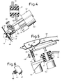
- Fig. 4 shows that on the mounting frame 10 - a piston-cylinder unit 42 is attached via an elastic intermediate member 41, which is provided as an actuating device for parts to be clipped (so-called clip elements).
- clip elements Such a clip element is designated 43 in FIGS. 4 and 6.
- This is a so-called blind plug or cover, which on the one hand serves to connect the headlining 24 to the roof frame 44 and on the other hand has the task of receiving screws 45 and at the same time serving to center the screw connection to be fitted (see FIG. 4) .
- the blind plug 43 has a conical finder pin 46, which is used to make it easier to find the mounting position (FIG. 4).
- a plurality of locking lamellae 47 are attached, with the aid of which the blind plug 43 is held in the assembly position shown in FIG. 4.
- the blind plug 43 is pressed into the assembly position by means of the piston-cylinder unit 42 already mentioned, the piston 48 of which, as can be seen in FIG. 4, can be moved back and forth in the direction of arrow 49.
- a centering sleeve 51 is connected to the piston 48 - at 50 - which, after preassembly of the blind plug 42, is put thereon (FIG. 4).
- screwdriver which is numbered 52
- angle screwdriver This has a rotatable pin 53, the free end of which cooperates within the centering sleeve 51 already mentioned with the self-tapping screw 45 located there.
- the screw 45 is screwed into the blind plug 43.
- the holding elements 20, 21 of the assembly frame 10 can be unlocked, so that the claw of the assembly frame 10 is released.
- the assembly frame 10 can then be lowered by means of the movement device 36 and finally moved out of the body 25.
- the assembly frame 10 can be loaded again with parts to be preassembled, as described above. Before doing so, the correct final assembly positions of the parts mounted on the body 25 should be checked. Signaling switches can be used for this in a manner known per se.
Landscapes
- Engineering & Computer Science (AREA)
- Mechanical Engineering (AREA)
- Manufacturing & Machinery (AREA)
- Chemical & Material Sciences (AREA)
- Combustion & Propulsion (AREA)
- Transportation (AREA)
- Body Structure For Vehicles (AREA)
- Automobile Manufacture Line, Endless Track Vehicle, Trailer (AREA)
- Vehicle Interior And Exterior Ornaments, Soundproofing, And Insulation (AREA)
Abstract
Description
Verfahren zum Einbau eines Dachhimmels nebst anderer von innen am Dach zu befestigender Teile von Kraftfahrzeugen, insbesondere Personenkraftwagen, und Vorrichtung zur Durchführung des VerfahrensMethod for installing a headliner along with other parts of motor vehicles, in particular passenger cars, to be fastened from the inside, and device for carrying out the method
Die Erfindung bezieht sich auf ein Verfahren zum Einbau eines Dachhimmels, nebst anderer von innen am Dach zu befestigender Teile, wie Sonnenblenden, Haltegriffe und dergleichen mehr, in einer Karosserie von Kraftfahrzeugen, insbesondere Personenkraftwagen.The invention relates to a method for installing a headliner, in addition to other parts to be fastened from the inside to the roof, such as sun visors, grab handles and the like, in a body of motor vehicles, in particular passenger cars.
Nach dem bisherigen Stand der Technik ist es üblich, Teile der vorgenannten Art in zeitaufwendiger, schwieriger und anstrengender Uberkopfarbeit manuell in KraftfahrzeugKarosserien einzubauen.According to the prior art, it is customary to manually install parts of the aforementioned type in motor vehicle bodies in time-consuming, difficult and strenuous overhead work.
Aufgabe der Erfindung ist es, Maßnahmen dafür zu treffen, daß die in Rede stehenden Teile einfacher, schneller und unter geringerem Kostenaufwand montiert werden können. Erfindungsgemäß wird die Aufgabe dadurch gelöst, daB der Dachhimmel und die anderen Teile auf einem Montagegestell im Stand neben dem Endmontageband zu einer Montageeinheit vormontiert werden und daß die Montageeinheit anschließend durch eine Fensteröffnung, vorzugsweise durch die Front-oder Heckscheiben- oder Heckklappenöffnung, in die Karosserie eingefahren, in Dachrahmenhöhe angehoben und durch die Fenster- und/oder Türöffnungen - seitlich und/oder längs in Montageposition mit der Karosserie verkrallt wird und daß anschließend die Endmontage der auf der Montageeinheit befindlichen Teile an der Karosserie erfolgt und daß anschließend die Verkrallung gelöst, das Montagegestell abgesenkt und schließlich wieder aus der Karosserie herausgefahren wird.The object of the invention is to take measures so that the parts in question can be assembled more easily, quickly and at lower cost. According to the invention, the object is achieved in that the headliner and the other parts are preassembled on a mounting frame in the stand next to the final assembly line to form an assembly unit, and in that the assembly unit then into the body through a window opening, preferably through the front or rear window or tailgate opening retracted, raised to the roof frame height and through the window and / or door openings - sideways and / or lengthways in Mon day position is clawed to the body and that then the final assembly of the parts located on the assembly unit is carried out on the body and that then the claw is released, the mounting frame is lowered and finally moved out of the body.
Die Erfindung gestattet vorteilhafterweise eine weitgehende Automatisierung der Montage des Dachhimmels, nebst der in diesem Bereich liegenden Einzelteile innerhalb der Kraftfahrzeugkarosserie.The invention advantageously permits extensive automation of the assembly of the roof lining, along with the individual parts located in this area, within the motor vehicle body.
In vorteilhafter Weiterbildung des Grundgedankens der Erfindung kann die Vormontage der Teile am Montagegestell in folgender Reihenfolge vorgenommen werden:
- 1. Einlegen der Haltegriffe
- 2. Einlegen von Blindstopfen anstelle eines Haltegriffes
- 3. Einlegen der Sonnenblenden
- 4. Einlegen der Sonnenblendenböckchen.
- 5. Positionierung der Abschlußleiste hinten.
- 6. Einlegen des Fertighimmels
- 1. Insert the handles
- 2. Insert blind plugs instead of a handle
- 3. Insert the sun visors
- 4. Insert the sun visor lugs.
- 5. Positioning the end strip at the rear.
- 6. Insert the finished roof
Die Vormontage der Teile am Montagegestell kann von Hand oder automatisch erfolgen.The parts can be pre-assembled on the assembly frame by hand or automatically.
Nach weiteren wichtigen Merkmalen der Erfindung ist eine Vorrichtung zur Durchführung des Verfahrens gekennzeichnet durch ein Montagegestell mit Aufnahme- und Lösevorrichtungen für die in die Karosserie einzubauenden Teile, derart, daß die Teile entsprechend ihrer späteren Endmontageposition auf dem Montagegestell vormontierbar sind, und ferner dadurch, daß das Montagegestell mindestens an zwei gegenüberliegenden Seitenkanten, vorzugsweise an allen Seitenkanten, hakenartige bewegliche Halteelemente besitzt, die zugleich als Zentriervorrichtung für die Montageeinheit am Dach im Innern der Karosserie dienen.According to further important features of the invention, a device for performing the method is characterized by an assembly frame with receiving and releasing devices for the parts to be installed in the body, such that the parts can be preassembled on the assembly frame in accordance with their later final assembly position, and further in that the mounting frame has hook-like movable holding elements on at least two opposite side edges, preferably on all side edges, which at the same time serve as a centering device for the mounting unit on the roof inside the body.
Zweckmäßigerweise besitzt das Montagegestell Betätigungsvorrichtungen für die Endmontage der Teile, insbesondere Zylinder für alle zu klipsenden Teile (Klips-Elemente) und Schrauber für alle zu verschraubenden Teile (Schraubelemente).The assembly frame expediently has actuating devices for the final assembly of the parts, in particular cylinders for all parts to be clipped (clip elements) and screwdrivers for all parts to be screwed (screw elements).
Weitere Ausgestaltungen und Vorteile der Erfindung können den Unteransprüchen sowie - anhand von Ausführungsbeispielen - der Zeichnung und der nachstehenden Zeichnungsbeschreibung entnommen werden. Es zeigt:
- Fig. 1 - in perspektivischer Darstellung - ein Montagegestell während der Vormontage des Dachhimmels, nebst benachbarter Teile,
- Fig. 2 die vormontierte Montageeinheit während des Einfahrvorganges in eine Pkw-Karosserie, ebenfalls in perspektivischer Darstellung,
- Fig. 3 die Endstellung der vormontierten Montageeinheit unterhalb des Karosseriedaches, in Darstellung entsprechend Fig. 2,
- Fig. 4 einen Teilausschnitt des in Fig. 1 in seiner Gesamtheit dargestellten Montagegestells, in gegenüber Fig. 1 vergrößerter Darstellung,
- Fig. 5 einen weiteren Teilausschnitt aus dem Montagegestell nach Fig. 1, ebenfalls gegenüber der Darstellung nach Fig. 1 vergrößert, und
- Fig. 6 einen sogenannten Blinddeckel, entsprechend der Einzelheit "A" nach Fig. 4, in gegenüber Fig. 4 leicht vergrößerter Darstellung.
- 1 - in perspective - an assembly frame during the pre-assembly of the headliner, together with neighboring parts,
- Fig. 2, the pre-assembled assembly unit during Einfahrvor g anges in a car body, also in a perspective view,
- 3 shows the end position of the preassembled assembly unit below the body roof, in a representation corresponding to FIG. 2,
- 4 shows a partial section of the assembly frame shown in its entirety in FIG. 1, in an enlarged representation compared to FIG. 1,
- 5 shows a further partial section from the assembly frame according to FIG. 1, also enlarged compared to the illustration according to FIG. 1, and
- Fig. 6 shows a so-called blind cover, corresponding to the detail "A" according to Fig. 4, in a slightly enlarged representation compared to Fig. 4.
Nach Fig. 1 - 3 bezeichnet 10 ein im wesentlichen als Blechplatte ausgebildetes Montagegestell, welches verschiedene Halte- und Betätigungsvorrichtungen 11 - 15 besitzt. An der Unterseite des im wesentlichen Rechteckform aufweisenden Montagegestells 10 sind ferner - an allen vier Seitenkanten 16 - 19 - hakenförmige Halteelemente 20, 21 angebracht. Die Halteelemente 20, 21 sind durch Betätigungsvorrichtungen (nicht gezeigt) in Pfeilrichtung 22 bzw. 23 beweglich angeordnet.According to FIGS. 1-3, 10 denotes an assembly frame which is essentially designed as a sheet metal plate and which has various holding and actuating devices 11-15. On the underside of the
Aus Fig. 1 ist terner ersichtlich ein vorgefertigter Dachhimmel 24 für eine Pkw-Karosserie 25 (siehe Fig. 2 u. 3), welcher ·gerade in Vertikalrichtung von oben nach unten (Pfeilrichtung 26) auf dem Montagegestell 10 montiert wird. An dem Fertighimmel 24 sind verschiedene Ausnehmungen 27 und Aussparungen 28 vorgesehen, die in Vormontageposition des Dachhimmels 24 (siehe hierzu Fig. 2) mit Zentrierstiften 29 bzw. den bereits erwähnten Halteteilen 14 am Montagegestell 10 zusammenwirken. Der Dachhimmel 24 wird hierdurch am Montagegestell 10 fixiert. Außerdem sind an dem Montagegestell 10, wie Fig. 1 desweiteren erkennen läßt, Vertiefungen 30 zum Einlegen von Sonnenblenden (nicht gezeigt), sowie Ausnehmungen 31 zur Vormontage von Blindstopfen (vgl. hierzu Fig. 4 und 6) vorgesehen. Seitliche und obere Haltegriffe, z. B. 32, können an den Stellen 11, 12 und 13'vormontiert werden.Ig from F. 1 can also be seen a
Die Vormontage der erwähnten Teile erfolgt zweckmäßigerweise im Stand neben dem Endmontageband, (nicht gezeigt) entweder von Hand (Fig. 1) oder mit Automaten. Hierbei sollten zunächst die Haltegriffe, z. B. 32, eingelegt werden. Anschließend kann das Einlegen der Blindstopfen (vgl. Fig. 4 und 6) erfolgen. Danach sollten die Sonnenblenden und Sonnenblendenböckchen (nicht gezeigt) an den dafür vorgesehenen Stellen (30) vormontiert werden. Nach Vormontage der Abschlußleiste hinten (nicht gezeigt) kann der Fertigdachhimmel 24 eingelegt werden. Nun kann die vormontierte Montageeinheit - wie Fig. 2 und 3 zeigen - mittels einer in Vertikal- und Horizontalrichtung (vgl. Pfeile 33, 34 und 35 in Fig. 2) verfahrbaren Bewegungseinrichtung 36, die z. B. druckmittelgesteuert bzw. -betätigt sein kann, durch die Frontscheibenöffnung der Karosserie 25 in das Innere der Karosserie 25 eingefahren (vgl. Fig. 3).The preassembly of the parts mentioned is advantageously carried out in the stand next to the final assembly line (not shown) either by hand (FIG. 1) or with machines. Here, the handles, e.g. B. 32, are inserted. The blind plugs can then be inserted (see FIGS. 4 and 6). Then the sun visors and sun visor bracket (not shown) should be preassembled at the designated locations (30). After preassembling the rear cover strip (not shown), the finished
Nach der Positionierung der Montageeinheit in der in Fig. 3 in dünnen Linien angedeuteten Position im vertikalen Abstand unterhalb des Fahrzeugdaches 37 wird schließlich die Montageeinheit - ebenfalls mittels der Bewegungseinrichtung 36 - in Pfeilrichtung 38 vertikal angehoben bis der Fertig-Dachhimmel 24 an der Innenseite des Fahrzeugdaches 37 zur Anlage kommt. Nun ist die Endmontageposition des Fertig-Dachhimmels 24 bzw. der gesamten Montageeinheit erreicht. Die durch die Fenster- bzw. Türöffnungen der Karosserie 25 nach außen ragenden hakenförmigen Halteelemente 20, 21 werden nun in Pfeilrichtung 39 bzw. 40 nach innen bewegt bis ihre hakenförmig nach oben abgebogenen Enden mit den betreffenden Seitenkanten des Dachrahmens in Eingriff kommen (vgl. Pos. 20' bzw. 21' in Fig. 3). Die Montageeinheit ist nun mit der Fahrzeugkarosserie verkrallt und die Bewegungseinrichtung 36 kann von der Montageeinheit gelöst und von der Karosserie 25 wegbewegt werden.After positioning the assembly unit in the position indicated in thin lines in FIG. 3 at a vertical distance below the
Es folgt nunmehr die Endmontage der einzelnen auf der Montageeinheit vormontierten Bauteile. Es wird diesbezüglich insbesondere auf Fig. 4, 5 und 6 verwiesen. Fig. 4 läßt erkennen, daß an dem Montagegestell 10 - über ein elastisches Zwischenglied 41 eine Kolben-Zylinder-Einheit 42 angebracht ist, die als Betätigungsvorrichtung für zu klipsende Teile (sogenannte Klipselemente) vorgesehen ist. Ein derartiges Klipselement ist in Fig. 4 und 6 mit 43 bezeichnet. Es handelt sich hierbei um einen sogenannten Blindstopfen oder -deckel, der einerseits zur Verbindung des Dachhimmels 24 mit dem Dachrahmen 44 dient und andererseits die Aufgabe hat, Schrauben 45 aufzunehmen und gleichzeitig zur Zentrierung für die anzubringende Schraubverbindung zu dienen (vgl. Fig. 4).The final assembly of the individual components preassembled on the assembly unit now follows. In this regard, reference is made in particular to FIGS. 4, 5 and 6. Fig. 4 shows that on the mounting frame 10 - a piston-
Wie im einzelnen Fig. 6 erkennen läßt, besitzt der Blindstopfen 43 einen konischen Sucherstift 46, der zum erleichtei ten Auffinden der Montageposition (Fig. 4) dient. Am mittleren Teil des Sucherstiftes 46 sind mehrere Rastlamellen 47 angebracht, mit deren Hilfe der Blindstopfen 43 in der aus Fig. 4 ersichtlichen Montageposition gehalten wird. Das Eindrücken des Blindstopfens 43 in die Montageposition geschieht mittels der bereits erwähnten Kolben-Zylinder-Einheit 42, deren Kolben 48, wie aus Fig. 4 hervorgeht, in Pfeilrichtung 49 hin- und herbewegbar ist. Mit dem Kolben 48 ist - bei 50 - eine Zentrierhülse 51 verbunden, die nach Vormontage des Blindstopfens 42 auf diesen aufgestülpt wird (Fig. 4). Anschließend können nun die Schraub-elemente eingeschraubt werden. Zu diesem Zweck ist - wie insbesondere aus Fig. 5 ersichtlich ist - zusammen mit der zum Eindrücken der Klips-Elemente dienenden Kolben-Zylinder-Einheit 42 ein sogenannter Schrauber an dem Montagegestell 10 befestigt, der mit 52 beziffert ist. Es handelt sich hierbei um einen sogenannten Winkelschrauber. Dieser weist einen drehbaren Stift 53 auf, dessen freies Ende innerhalb der bereits erwähnten Zentrierhülse 51 mit der dort befindlichen Blechschraube 45 zusammenwirkt. Die Schraube 45 wird in den Blindstopfen 43 eingeschraubt.As can be seen in detail in FIG. 6, the
Nachdem sämtliche auf dem Montagegestell 10 vormontierten Teile in der beschriebenen Weise am Fahrzeugdach endmontiert sind, können die Halteelemente 20, 21 des Montagegestells 10 entriegelt werden, so daB sich die Verkrallung des Montagegestells 10 löst. Das Montagegestell 10 kann anschließend mittels der Bewegungseinrichtung 36 abgesenkt und schließlich aus der Karossierie 25 herausgefahren werden. Nach Wiedererreichen der Anfangsposition (vgl. Fig. 1) kann erneut eine Beladung des Montagegestells 10 mit vorzumontierenden Teilen, wie oben beschrieben, erfolgen. Vorher sollte noch eine Überprüfung der ordnungsgemäßen Endmontagepositionen der an der Karosserie 25 montierten Teile vorgenommen werden. Hierzu können in an sich bekannter Weise Meldeschalter dienen.After all parts preassembled on the
Claims (11)
Applications Claiming Priority (2)
| Application Number | Priority Date | Filing Date | Title |
|---|---|---|---|
| DE3428008 | 1984-07-28 | ||
| DE19843428008 DE3428008A1 (en) | 1984-07-28 | 1984-07-28 | METHOD FOR INSTALLING A ROOF HEADING AND OTHER PARTS OF MOTOR VEHICLES TO BE FIXED FROM THE INSIDE, IN PARTICULAR PERSONAL VEHICLES, AND DEVICE FOR CARRYING OUT THE METHOD |
Publications (3)
| Publication Number | Publication Date |
|---|---|
| EP0170086A2 true EP0170086A2 (en) | 1986-02-05 |
| EP0170086A3 EP0170086A3 (en) | 1987-11-19 |
| EP0170086B1 EP0170086B1 (en) | 1989-10-11 |
Family
ID=6241899
Family Applications (1)
| Application Number | Title | Priority Date | Filing Date |
|---|---|---|---|
| EP85108227A Expired EP0170086B1 (en) | 1984-07-28 | 1985-07-03 | Device for mounting a roof lining, apart from other parts, from the interior of a vehicle body of a motor vehicle, especially a passenger car |
Country Status (2)
| Country | Link |
|---|---|
| EP (1) | EP0170086B1 (en) |
| DE (2) | DE3428008A1 (en) |
Cited By (9)
| Publication number | Priority date | Publication date | Assignee | Title |
|---|---|---|---|---|
| DE4005884A1 (en) * | 1990-02-24 | 1991-08-29 | Webasto Ag Fahrzeugtechnik | Support frame used in assembly of vehicle roof - incorporates variable position bearing elements for roof variants |
| EP0675035A1 (en) * | 1994-03-31 | 1995-10-04 | Mazda Motor Corporation | Apparatus and method for assembling motor vehicle |
| EP0688697A1 (en) * | 1994-06-20 | 1995-12-27 | Grupo Antolin-Ingenieria, S.A. | Self-supporting roof with built-in fittings directly mountable upon vehicle roofs |
| WO1996009952A1 (en) * | 1994-09-27 | 1996-04-04 | Donnelly Corporation | Modular panel assembly |
| WO1999065759A1 (en) * | 1998-06-18 | 1999-12-23 | Alusuisse Technology & Management Ag | Roof unit and floor unit for a road vehicle |
| US6860014B2 (en) * | 1998-06-18 | 2005-03-01 | Alcan Technology & Management Ltd. | Roof unit and basic structure of a road-bound vehicle |
| US6862809B2 (en) | 1998-06-18 | 2005-03-08 | Alcan Technology & Management Ltd. | Manufacturing process of roof unit and basic structure of a road-bound vehicle |
| US6918169B2 (en) * | 2002-05-14 | 2005-07-19 | Mathson Industries | Method of assembling a vehicle |
| US7076877B2 (en) | 1998-06-18 | 2006-07-18 | Alcan Technology & Management, Ltd. | Roof unit and floor unit for a road vehicle |
Families Citing this family (16)
| Publication number | Priority date | Publication date | Assignee | Title |
|---|---|---|---|---|
| DE3618999A1 (en) * | 1986-06-05 | 1987-12-10 | Goeppinger Kaliko Kunstleder | PASSENGER VEHICLE |
| JPH01306139A (en) * | 1988-06-03 | 1989-12-11 | Honda Motor Co Ltd | Automatic assembling device |
| US5267385A (en) * | 1988-06-03 | 1993-12-07 | Honda Giken Kogyo Kabushiki Kaisha | Automatic assembly apparatus |
| DE3820845C2 (en) * | 1988-06-21 | 1994-04-14 | Webasto Ag Fahrzeugtechnik | Mounting unit for vehicle roofs |
| DE4306178A1 (en) * | 1993-02-27 | 1994-09-01 | Goerlitz Waggonbau Gmbh | Method for mounting and dismounting pieces of equipment in the roof area of vehicles, in particular rail vehicles |
| DE4341574A1 (en) * | 1993-02-27 | 1995-06-08 | Goerlitz Waggonbau Gmbh | Method of loading equipment in railway vehicle roof space |
| DE9417791U1 (en) * | 1994-11-05 | 1995-02-02 | Magna Zippex Autotechnik Gmbh | Roof mounting assembly for vehicles |
| US6623068B2 (en) | 1998-06-18 | 2003-09-23 | Alcan Technology & Management Ag | Roof unit and basic structure of a road-bound vehicle |
| DE19847496B4 (en) | 1998-10-15 | 2004-01-29 | Daimlerchrysler Ag | B-pillar roof module |
| DE19847495B4 (en) | 1998-10-15 | 2004-01-29 | Daimlerchrysler Ag | A-pillar roof module |
| DE19853820A1 (en) * | 1998-11-21 | 2000-05-31 | Daimler Chrysler Ag | Roof module for motor vehicle has additional fastening in form of several threaded holes in roof module to accept screws which attach roof module to frame |
| DE19942894A1 (en) * | 1999-09-08 | 2001-03-15 | Volkswagen Ag | Device for stiffening a headliner of a motor vehicle |
| US6575528B2 (en) * | 2001-10-19 | 2003-06-10 | Lear Corporation | Modular overhead console assembly |
| DE10359983B3 (en) * | 2003-12-19 | 2005-09-01 | Misslbeck Technologies Ag | Assembly and tuning stand and method for fit test of a vehicle interior |
| JP7010083B2 (en) * | 2018-03-15 | 2022-01-26 | 日産自動車株式会社 | Assembly method |
| JP7035660B2 (en) * | 2018-03-15 | 2022-03-15 | 日産自動車株式会社 | Assembly method and assembly device |
Citations (3)
| Publication number | Priority date | Publication date | Assignee | Title |
|---|---|---|---|---|
| FR2445247A1 (en) * | 1978-12-29 | 1980-07-25 | Nissan Motor | PAVILION FOR A VEHICLE ROOF, AND ITS MANUFACTURING METHOD |
| DE3249454A1 (en) * | 1982-11-10 | 1984-05-10 | Audi Nsu Auto Union Ag, 7107 Neckarsulm | Method for mounting prefabricated roof linings in vehicle bodies |
| DE3241615A1 (en) * | 1982-11-10 | 1984-05-10 | Audi Nsu Auto Union Ag, 7107 Neckarsulm | METHOD FOR ASSEMBLY OF FINISHED SKIES IN VEHICLES AND DEVICE FOR IMPLEMENTING THE METHOD |
Family Cites Families (5)
| Publication number | Priority date | Publication date | Assignee | Title |
|---|---|---|---|---|
| GB1223598A (en) * | 1968-04-09 | 1971-02-24 | Rootes Motors Ltd | Improvements in or relating to vehicle bodies |
| DE2221192C3 (en) * | 1972-04-29 | 1981-08-13 | Daimler-Benz Ag, 7000 Stuttgart | Fastening the edges of the interior linings of motor vehicle roofs |
| DE8115083U1 (en) * | 1981-05-21 | 1981-11-12 | Translift AG, 6010 Kriens, Luzern | Device for transporting and automatically picking up body parts at different locations |
| DE3208804A1 (en) * | 1982-03-11 | 1983-09-29 | Adam Opel AG, 6090 Rüsselsheim | INTERIOR COVERING (SKY) OF VEHICLE ROOFS |
| IT1158820B (en) * | 1983-03-04 | 1987-02-25 | Comau Spa | PROGRAMMABLE SYSTEM FOR ASSEMBLY BY SCREWING THE VARIOUS MECHANICAL PARTS THE VEHICLES TO THEIR RESPECTIVE BODIES |
-
1984
- 1984-07-28 DE DE19843428008 patent/DE3428008A1/en active Granted
-
1985
- 1985-07-03 EP EP85108227A patent/EP0170086B1/en not_active Expired
- 1985-07-03 DE DE8585108227T patent/DE3573577D1/en not_active Expired
Patent Citations (3)
| Publication number | Priority date | Publication date | Assignee | Title |
|---|---|---|---|---|
| FR2445247A1 (en) * | 1978-12-29 | 1980-07-25 | Nissan Motor | PAVILION FOR A VEHICLE ROOF, AND ITS MANUFACTURING METHOD |
| DE3249454A1 (en) * | 1982-11-10 | 1984-05-10 | Audi Nsu Auto Union Ag, 7107 Neckarsulm | Method for mounting prefabricated roof linings in vehicle bodies |
| DE3241615A1 (en) * | 1982-11-10 | 1984-05-10 | Audi Nsu Auto Union Ag, 7107 Neckarsulm | METHOD FOR ASSEMBLY OF FINISHED SKIES IN VEHICLES AND DEVICE FOR IMPLEMENTING THE METHOD |
Cited By (11)
| Publication number | Priority date | Publication date | Assignee | Title |
|---|---|---|---|---|
| DE4005884A1 (en) * | 1990-02-24 | 1991-08-29 | Webasto Ag Fahrzeugtechnik | Support frame used in assembly of vehicle roof - incorporates variable position bearing elements for roof variants |
| EP0675035A1 (en) * | 1994-03-31 | 1995-10-04 | Mazda Motor Corporation | Apparatus and method for assembling motor vehicle |
| EP0688697A1 (en) * | 1994-06-20 | 1995-12-27 | Grupo Antolin-Ingenieria, S.A. | Self-supporting roof with built-in fittings directly mountable upon vehicle roofs |
| WO1996009952A1 (en) * | 1994-09-27 | 1996-04-04 | Donnelly Corporation | Modular panel assembly |
| WO1999065759A1 (en) * | 1998-06-18 | 1999-12-23 | Alusuisse Technology & Management Ag | Roof unit and floor unit for a road vehicle |
| US6860014B2 (en) * | 1998-06-18 | 2005-03-01 | Alcan Technology & Management Ltd. | Roof unit and basic structure of a road-bound vehicle |
| US6862809B2 (en) | 1998-06-18 | 2005-03-08 | Alcan Technology & Management Ltd. | Manufacturing process of roof unit and basic structure of a road-bound vehicle |
| US7076877B2 (en) | 1998-06-18 | 2006-07-18 | Alcan Technology & Management, Ltd. | Roof unit and floor unit for a road vehicle |
| US7243988B2 (en) | 1998-06-18 | 2007-07-17 | Alcan Technology & Management Ltd. | Roof unit and basic structure of a road-bound vehicle |
| US7568287B2 (en) | 1998-06-18 | 2009-08-04 | Alcan Technology & Management Ltd. | Roof unit and basic structure of road-bound vehicle |
| US6918169B2 (en) * | 2002-05-14 | 2005-07-19 | Mathson Industries | Method of assembling a vehicle |
Also Published As
| Publication number | Publication date |
|---|---|
| DE3428008C2 (en) | 1992-07-02 |
| DE3573577D1 (en) | 1989-11-16 |
| DE3428008A1 (en) | 1986-02-06 |
| EP0170086A3 (en) | 1987-11-19 |
| EP0170086B1 (en) | 1989-10-11 |
Similar Documents
| Publication | Publication Date | Title |
|---|---|---|
| EP0170086B1 (en) | Device for mounting a roof lining, apart from other parts, from the interior of a vehicle body of a motor vehicle, especially a passenger car | |
| DE4313555C1 (en) | Roof construction for motor vehicle - has master points on roof spars, and modular roof inserts are fastened to these via roof battens | |
| DE19946804C2 (en) | Vehicle roof module with integrated sunroof unit | |
| DE3435813C2 (en) | Method and device for height adjustment and assembly of the cover of a sliding and / or lifting roof structure to be built into a motor vehicle roof | |
| DE69930208T2 (en) | Profilteilbefestigung for the load carrier of a motor vehicle | |
| DE19919505A1 (en) | Vehicle roof with inserted roof module and assembly process for it | |
| DE3127998C2 (en) | Guide device for sliding doors on motor vehicles | |
| DE3532104A1 (en) | PRE-ASSEMBLED UNIT FOR VEHICLE SLIDING ROOFS | |
| DE19521061C1 (en) | Installation tool for sliding roof frame into motor vehicles | |
| DE10063459A1 (en) | Lightweight door for motor vehicles | |
| DE3540814C2 (en) | ||
| DE3622483A1 (en) | BUMPER FOR VEHICLES | |
| DE3311599A1 (en) | DOOR OF A MOTOR VEHICLE AND METHOD FOR MOUNTING THE DOOR | |
| EP0096846B1 (en) | Body for motor vehicles, especially for passenger cars, and method of manufacturing such a body | |
| DE19960784A1 (en) | Roof mounting on motor vehicles | |
| DE10301661B4 (en) | Mounting assembly for attaching a sun visor | |
| DE3622165A1 (en) | PRE-ASSEMBLED UNIT FOR THE COCKPIT AREA OF MOTOR VEHICLES, ESPECIALLY PERSONAL VEHICLES, AND METHOD FOR INSTALLING SUCH A UNIT | |
| DE4426155C2 (en) | Motor vehicle, in particular passenger cars | |
| EP0513583B1 (en) | Device for slidable fixing the lateral parts of a bumper to a car body | |
| DE3311441C2 (en) | Upper ridge sunroof | |
| DE19714404A1 (en) | Assembly structure of door frame for motor vehicle | |
| DE60003256T2 (en) | Cladding arrangement for a motor vehicle sheet metal part | |
| DE10334734B4 (en) | Fastening device with tolerance compensation | |
| DE10055664B4 (en) | Roof arrangement for a vehicle | |
| DE202011051781U1 (en) | Door module for a vehicle door |
Legal Events
| Date | Code | Title | Description |
|---|---|---|---|
| PUAI | Public reference made under article 153(3) epc to a published international application that has entered the european phase |
Free format text: ORIGINAL CODE: 0009012 |
|
| AK | Designated contracting states |
Designated state(s): DE FR GB IT SE |
|
| 17P | Request for examination filed |
Effective date: 19860530 |
|
| PUAL | Search report despatched |
Free format text: ORIGINAL CODE: 0009013 |
|
| AK | Designated contracting states |
Kind code of ref document: A3 Designated state(s): DE FR GB IT SE |
|
| 17Q | First examination report despatched |
Effective date: 19880816 |
|
| ITF | It: translation for a ep patent filed |
Owner name: BARZANO' E ZANARDO ROMA S.P.A. |
|
| GRAA | (expected) grant |
Free format text: ORIGINAL CODE: 0009210 |
|
| AK | Designated contracting states |
Kind code of ref document: B1 Designated state(s): DE FR GB IT SE |
|
| GBT | Gb: translation of ep patent filed (gb section 77(6)(a)/1977) | ||
| REF | Corresponds to: |
Ref document number: 3573577 Country of ref document: DE Date of ref document: 19891116 |
|
| ET | Fr: translation filed | ||
| ITTA | It: last paid annual fee | ||
| PLBE | No opposition filed within time limit |
Free format text: ORIGINAL CODE: 0009261 |
|
| STAA | Information on the status of an ep patent application or granted ep patent |
Free format text: STATUS: NO OPPOSITION FILED WITHIN TIME LIMIT |
|
| 26N | No opposition filed | ||
| PGFP | Annual fee paid to national office [announced via postgrant information from national office to epo] |
Ref country code: SE Payment date: 19920610 Year of fee payment: 8 |
|
| REG | Reference to a national code |
Ref country code: GB Ref legal event code: 746 |
|
| PG25 | Lapsed in a contracting state [announced via postgrant information from national office to epo] |
Ref country code: SE Effective date: 19930704 |
|
| PGFP | Annual fee paid to national office [announced via postgrant information from national office to epo] |
Ref country code: FR Payment date: 19940721 Year of fee payment: 10 |
|
| EUG | Se: european patent has lapsed |
Ref document number: 85108227.1 Effective date: 19940210 |
|
| PGFP | Annual fee paid to national office [announced via postgrant information from national office to epo] |
Ref country code: GB Payment date: 19950707 Year of fee payment: 11 |
|
| PG25 | Lapsed in a contracting state [announced via postgrant information from national office to epo] |
Ref country code: FR Effective date: 19960430 |
|
| REG | Reference to a national code |
Ref country code: FR Ref legal event code: ST |
|
| REG | Reference to a national code |
Ref country code: FR Ref legal event code: ST |
|
| REG | Reference to a national code |
Ref country code: FR Ref legal event code: ST |
|
| PG25 | Lapsed in a contracting state [announced via postgrant information from national office to epo] |
Ref country code: GB Effective date: 19960703 |
|
| GBPC | Gb: european patent ceased through non-payment of renewal fee |
Effective date: 19960703 |
|
| PGFP | Annual fee paid to national office [announced via postgrant information from national office to epo] |
Ref country code: DE Payment date: 20000920 Year of fee payment: 16 |
|
| PG25 | Lapsed in a contracting state [announced via postgrant information from national office to epo] |
Ref country code: DE Free format text: LAPSE BECAUSE OF NON-PAYMENT OF DUE FEES Effective date: 20020501 |