EP0169718A2 - Conical cutters for drill bits and processes to produce same - Google Patents
Conical cutters for drill bits and processes to produce same Download PDFInfo
- Publication number
- EP0169718A2 EP0169718A2 EP85305165A EP85305165A EP0169718A2 EP 0169718 A2 EP0169718 A2 EP 0169718A2 EP 85305165 A EP85305165 A EP 85305165A EP 85305165 A EP85305165 A EP 85305165A EP 0169718 A2 EP0169718 A2 EP 0169718A2
- Authority
- EP
- European Patent Office
- Prior art keywords
- core
- combination
- metallic
- inserts
- layer
- Prior art date
- Legal status (The legal status is an assumption and is not a legal conclusion. Google has not performed a legal analysis and makes no representation as to the accuracy of the status listed.)
- Granted
Links
Images
Classifications
-
- B—PERFORMING OPERATIONS; TRANSPORTING
- B22—CASTING; POWDER METALLURGY
- B22F—WORKING METALLIC POWDER; MANUFACTURE OF ARTICLES FROM METALLIC POWDER; MAKING METALLIC POWDER; APPARATUS OR DEVICES SPECIALLY ADAPTED FOR METALLIC POWDER
- B22F7/00—Manufacture of composite layers, workpieces, or articles, comprising metallic powder, by sintering the powder, with or without compacting wherein at least one part is obtained by sintering or compression
- B22F7/06—Manufacture of composite layers, workpieces, or articles, comprising metallic powder, by sintering the powder, with or without compacting wherein at least one part is obtained by sintering or compression of composite workpieces or articles from parts, e.g. to form tipped tools
-
- E—FIXED CONSTRUCTIONS
- E21—EARTH OR ROCK DRILLING; MINING
- E21B—EARTH OR ROCK DRILLING; OBTAINING OIL, GAS, WATER, SOLUBLE OR MELTABLE MATERIALS OR A SLURRY OF MINERALS FROM WELLS
- E21B10/00—Drill bits
- E21B10/08—Roller bits
- E21B10/22—Roller bits characterised by bearing, lubrication or sealing details
-
- E—FIXED CONSTRUCTIONS
- E21—EARTH OR ROCK DRILLING; MINING
- E21B—EARTH OR ROCK DRILLING; OBTAINING OIL, GAS, WATER, SOLUBLE OR MELTABLE MATERIALS OR A SLURRY OF MINERALS FROM WELLS
- E21B10/00—Drill bits
- E21B10/46—Drill bits characterised by wear resisting parts, e.g. diamond inserts
- E21B10/50—Drill bits characterised by wear resisting parts, e.g. diamond inserts the bit being of roller type
- E21B10/52—Drill bits characterised by wear resisting parts, e.g. diamond inserts the bit being of roller type with chisel- or button-type inserts
Definitions
- Thás invention relates generally to conical cutters (usually called cones) used in roller bits employed in oil- well drilling and in drilling of holes for mining purposes.
- the invention further concerns a process through which the conical cutters may be most conveniently manufactured as integrated composite structures, and secondly, novel cutters and cutter component structures as well as composition thereof provide important properties associated with localised sections of the cutters.
- Conical cutters must operate under severe environmental conditions and withstand a variety of "bit-life" reducing interactions with the immediate surroundings. These include abrasive or erosive actions of the rock being drilled, impact, compressive and vibrational forces that result from rotation of the bit under the weight put on the bit, and the sliding wear and impact actions of the journal pin around which the cone is rotating.
- bit-life reducing interactions with the immediate surroundings. These include abrasive or erosive actions of the rock being drilled, impact, compressive and vibrational forces that result from rotation of the bit under the weight put on the bit, and the sliding wear and impact actions of the journal pin around which the cone is rotating.
- the severity, as well as the variety of life-reducing forces acting upon conical cutters dictate that these cutters not be made of a simple material of uniform properties if they are to provide a cost-effective, down-hole service life. Instead, localised properties of cone sections should withstand the localised forces acting on those sections.
- TCI tungsten carbide inserts
- the cone body normally requires surface hardening to withstand the erosive/abrasive effect of rock drilling. This may be accomplished by any of the widely used surface modification or coating techniques, such as transformation hardening, carburizing, nitriding, hard-facing, hard metal coating or brazed-on hard metal cladding.
- interior surfaces of the cone are required in certain areas to be hard, wear and impact resistant to accomodate loading from both the thrust and the radial directions (with respect to the journal pin axial direction). Consequently, these surfaces are also hardened by a surface hardening process.
- the pin surfaces likely to contact "thrust bearing"-surfaces are usually hardfaced and run against a hardened cone or a hardened nose button insert in the cone or a carburized tool steel bushing.
- a row of uncapped balls run in races between the nose pin and the roller or journal bearing. These balls may carry some thrust loading, but their primary function is to retain the cone on the journal pin when not pressing against the bottom of the hole.
- the major load is the radial load and is carried substantially either by a full complement of cylindrical rollers used primarily in mining operations, or a sealed journal bearing used in oil-field drilling.
- the journal bearings are normally operated with grease lubrication and employ additional support to prolong bearing life, i.e. self-lubricating porous floating rings (1) , beryllium-copper alloy bearing coated with a soft metal lubricating film (2,3), a bearing with inlays of soft metal to provide lubrication and heat transfer (4), or an aluminium bronze inlay ( 5 ) in the cone as the soft, lubricating member of the journal-cone bearing couple.
- Cone surfaces must also be treated to impart the desired localised properties. These treatments are usually long i.e., carburizing; or inadequate, i.e. hard coatings that are sprayed or electro-deposited, or have side effects that compromise ovreall properties of the cone, i.e. hardfacing of weld cladding cause heat-affected regions of inferior properties.
- the subject processes involve near isostatic hot pressing of cold formed powders. See U.S. Patents 3,356,496 and 3,689,259.
- the basic process isostatically hot presses near net shape parts in a matter of a few minutes, producing properties similar to those produced by the conventional Hot Isostatic Pressing (HIP) process without the lengthy thermal cycle required by HIPing.
- HIP Hot Isostatic Pressing
- the resultant roller bit cutter basically comprises:
- the inserts may consist of tungsten carbide; the core typically defines multiple recesses receiving the insert anchor portions, the outer metallic layer extending into said recesses and between the core and said insert anchor portions; at least one and typically all of the layers consist s or consist of consolidated power metal; the insert anchor portions typically have non-parallel side surfaces, and said outer layer has non-parallel sided portions compressively engaging said insert ends, in the recesses.
- the core typically consists of steel alloyed with elements that include carbon, manganese, silicon, nickel, chromium, molybdenum, and copper, or the core may consist of cast alloy steel, or of ultra high strength steel.
- the outer layer may consist of a composite mixture of refractory particles in a binder metal such particles typically having micro hardness in excess of 1,000kg/mm 2 , and a melting point in excess of 1,600°C.
- the refractory particles are typically selected from the group consisting of Ti, W, Al, V, Zr, Cr, Mo, Ta, Nb, Hf and carbides, oxides, nitrides and borides thereof.
- the outer layer may consist of tool steel initially in powder form, or of a hardfacing alloy, as will be seen, or of wear resistant, intermetallic Laves phase materials, as will appear.
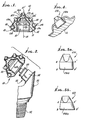
- figure 1 is an elevation, in section of a conical cutter used in three cone rock bits
- the illustrated improved roller bit cutter 10 includes a tough, metallic, generally conical and fracture resistant core 11.
- the core has a hollow interior 12, and defines a central axis 13 of rotation.
- the bottom of the core is tapered at 14, and the interior includes multiple successive zones 12a, 12b, 12c, 12d, 12e and 12f,concentri6:to axis 13, as shown.
- An annular metallic radial (sleeve type) bearing layer 15 is carried by the core at interior zone 12a to support the core for rotation.
- Layer 15 is attached to annular surface - lla of the core, and extends about axis 13. It consists of a bearing alloy, as will appear.
- An impact and wear resistant metallic inner layer 16 is attached to the core at its interior zones 12b - 12f, to provide an axial thrust bearing; as at end surface 16a.
- a plurality of hard metallic inserts 17, as for example of tungsten carbide, have inner anchor portions 17a carried by the core to be partly embedded or received in core recesses 18.
- the inserts also have portions 17b that protrude outwardly, as shown, to define cutters (see also Figures 4, 5a and 5b), at least some of the inserts spaced about axis 13.
- One insert 17' may be located at the extreme outer end of the core, at axis 13.
- a wear resistant outer metallic skin or layer 19 is on and attached to the core exterior surface, to extend completely over that surface including the surfaces of the core portions that define the recesses 18, whereby the inserts are in fact attached to the layer portions 19a in those recesses.
- At least one or two of the layers 15, 16 and 19 consists of consolidated powder metal,and preferably all three layers consist of such consolidated powder metal.
- a variety of manufacturing schemes are possible using the herein disclosed hot pressing technique and the alternative means of applying the surface layers indicated in Figure 1. It is seen from the previous discussion that surface layers, 15, 16 and 19 are to have quite different engineering properties other than the interior core section 11. Similarly, layers 16 and 19 should be different than 15, and even 16 should differ from 19. Each of these layers and the core piece 11 may, therefore, be manufactured separately or applied in place as powder mixtures prior to cold pressing. Thus, there may be a number of possible processing schemes as indicated by arrows in Figure 3. The encircled numbers in this figure refer to the possible processing steps (or operations) listed in below Table 1. Each continuous path in the figure, starting from Step No. 1 and ending at Step No. 15, defines a separate processing scher.e which, when followed, is capable of producing integrally consolidate composite conical cutters.
- the processing schemes outlined include only the major steps involved in the flow of processing operations.
- Other secondary operations that are routinely used in most processing schemes for similarly manufactured products, are not included for sake of simplicity. These may be cleaning, manual patchwork to repair small defects, grit blasting to remove loose particles or oxide scale, dimensional or structural inspections etc.
- Interior core piece 11 should be made of an alloy possessing high strength and toughness, and preferably requiring thermal treatments below 1700°F (to reduce damage due to cooling stresses) to impart its desired mechanical properties. Such restrictions can be met by the following classes of materials:
- refractory hard compounds include carbides, oxides, nitrides and borides (or their mixtures) of elements Ti, W, Al, V, Zr, Cr, Mo, Ta, Nb and Hf.
- Hardfacing alloys based on transition elements Fe, Ni or Co with the following general chemistry ranges:
- Thrust-bearing 16 may be similar in composition to the exterior skin 19. in addition, when they are incorporated into the cone as inserts (pre-formed, separately processed cast, wrought or powder metal-produced shapes), they may be made of any metal or alloy having a hardness above 35 R . They may, in such cases, have a composite structure where part of the structure is a lubricating material such as molybdenum disulfide, tin, copper, silver, lead or their alloys, or graphite.
- a lubricating material such as molybdenum disulfide, tin, copper, silver, lead or their alloys, or graphite.
- Cobalt-cemented Tungsten carbide Inserts 17 in Figure 1 are to be readily available cobalt-tungsten carbide compositions whose cobalt content usually is within the 5 -18% range.
- Bearing alloy 15 if incorporated into the cone as a separately-manufactured insert, may either be a hardened or carburized or nitrided or borided steel or any one of a number of readily available commercial non-ferrous bearing alloys, such as the bronzes. If the bearing 1s weld deposited, the material may still be a bronze. If, however, the.bearing is integrally hot pressed in place from a previously applied powder, or if the insert is produced by any of the known powder metallurgy techniques, then it may also have a composite structure having dispersed within it a phase containing lubricating properties to the bearing.
- the cone configuration accords with the journal pin shape and is affected by the interaction of the cone with the other cones of the same bit. While configuration may vary somewhat, there are certain configurations associated with the cone sections identified as 11, 15, 16, 17 and 19 which are unusually advantageous, and are listed as follows:
- a typical processing route involves the steps numbered 1, 3, 5, 6, 7, 10, 11, 12 and 15 in Table 1.
- a low alloy steel composition is blended to form a powder mixture of composition suitable for the core.
- this mixture constituted an alloy having the following final analysis: 0.22% manganese, 0.23% molybdenum, 1.84% nickel, 0.27% carbon and remainder substantially iron.
- the powder was cold pressed to a preform and sintered at 2050°F for one hour in a reducing furnace atmosphere.
- Carbide inserts were placed in the blind holes created in the preform and the exterior of the cone was painted with a slurry containing hardfacing metal powder, Stellite No. 1, making sure the slurry filled all clearance space between the carbide insert and the preform.
- the slurry was prepared by mixing Stellite powder with 3% cellulose acetate powder and adding sufficient amount of acetone to develop the desired slurry fluidity.
- the Stellite No. 1 alloy powder had a nominal chemistry (in weight percent) of: 30% chromium, 2.5% carbon, 1% silicon, 12.5% tungsten, 1% maximum each of manganese and molybdenum, and 3% maximum each of iron and nickel, with remainder being substantially cobalt.
- a thin layer of a thrust bearing alloy was similarly applied on surfaces identified by 16 in Figure 1.
- the composition of this layer was the same as the exterior skin applied over the core piece.
- a radial bearing alloy tube segment was then fitted within the cylindrical section identified as 15 in Figure 1.
- the AISI 105 carbon steel tube having 0.1 inch wall thickness was fixed in place by placing it on a thin layer of slurry applied core piece alloy steel powder.
- the preform assembly thus prepared, was dried in an oven at 100°F for overnight, driving away all volatile constituents of the slurries. It was then induction heated to 2250°F in less than 4 minutes and immersed in hot ceramic grain, which was also at 2250°F, within a cylindrical die. A pressure of 40 tons per square inch was applied, by way of a hydraulic press, onto the grain which transmitted the pressure, in various degrees, to the preform in all directions. The peak press pressure of 40 tsi was reached within 4 - 5 seconds and the peak pressure was maintained for less than 2 seconds and released. The die contents when emptied separated into grain and the consolidated conical cutter.
- the furnace atmosphere was adjusted to be a reducing atmosphere, e.g. cracked ammonia.
- the hardened part was then tempered for one hour at 1000°F and air cooled to assure
- powder slurry for the wear resistant exterior skin and the thrust bearing surface was prepared using a 1.5% by weight mixture of cellulose acetate with Stellite alloy No. 1 powder. This preform was dried at 250°F for two hours instead of 100°F for overnight and the remaining processing steps were identical to the above example. No visible differences were detected between the two parts produced by the two experiments.
- radial bearing alloy was affixed to the interior wall of the core through the use of a nickel powder slurry similarly prepared as above. -Once again the bond between the radial bearing alloy and the core piece was extremely strong as determined by separately conducted bonding experiments.
- composite is used both in the microstructural sense or form an engineering sense, whichever is more appropriate.
- a material made up of discrete fine phase(s) dispersed within another phase is considered a composite of phases, while a structure made up of discrete, relatively large regions joined or assembled by some means, together is also considered a “composite”.
- An alloy layer composed of a mixture of carbide particles in cobalt would micro-structurally be a composite layer, while a cone cutter composed of various distinct layers, TCl's and other inserts, would be a composite part as well.
- This invention introduces, for the first time, the following novel features to a TCI drill bit cone:
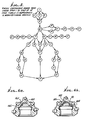
- Figure 2 shows the conical bit cutter 10 of the invention applied to the journal pin 50 on a bit body 51, having a threaded stem 52.
- Pin 50 also provides a ball bearing race 53 adapted to register with race surface 20 about zone 12b, and journal bearing 54 adapted to mount layer 15 as described.
- Step 3 of the process as listed in Table I is for example shown in Figure 7a, the arrows 100 and 101 indicating isostatic pressurisation of both interior and exterior surfaces of the core piece 11. Pressure application is effected for example by the use of rubber moulds or ceramic granules packed about the core, and pressurised. Blind holes are shown at 103. Steps 5 - 10 of the Table I process are indicated in Figure 7b. Step 11 of the process is exemplified by the induction heating step of Figure 7c.
- the hot part (cone, as in Figure 1) is indicated at 99 as embedded in hot ceramic grain 106, in shuttle die 107.
- the latter is then introduced into a press die 108 (see Figure 7e), and the outer wall 107a of the shuttle die is upwardly removed.
- Die 108 has cylindrical wall 108a and bottom wall 108b.
- Figure 7f is like Figure 7e, but shows a plunger 109 applying force to the grain 106, in response to fluid pressure application at 110 to the plunger via actuator cylinder 111. This corresponds to step 12 of the Table I process.
- the part 99 and grain 106 are upwardly ejected by a second plunger 112 elevating the bottom wall 107.
- the grain is removed from the part 106 and is recycled to step 7d.
- the consolidated part including its component may then be finished, as by grit blasting, finish machining and grinding, and inspected. See Step 15 of Table 1.
Landscapes
- Engineering & Computer Science (AREA)
- Geology (AREA)
- Life Sciences & Earth Sciences (AREA)
- Mining & Mineral Resources (AREA)
- Mechanical Engineering (AREA)
- General Life Sciences & Earth Sciences (AREA)
- Fluid Mechanics (AREA)
- Environmental & Geological Engineering (AREA)
- Physics & Mathematics (AREA)
- Geochemistry & Mineralogy (AREA)
- Chemical & Material Sciences (AREA)
- Composite Materials (AREA)
- Manufacturing & Machinery (AREA)
- Materials Engineering (AREA)
- Earth Drilling (AREA)
- Powder Metallurgy (AREA)
- Drilling Tools (AREA)
Abstract
- a) a tough, metallic generally conical and fracture resistant core having a hollow interior, the core defining an axis,
- b) an annular metallic radial bearing layer carried by said core at the interior thereof to support the core for rotation, said bearing layer extending about said axis,
- c) an impact and wear resistant metallic inner layer on the core at the interior thereof, to provide an axial thrust bearing, and
- d) hard metallic inserts having anchor portions carried by the core and partly embedded therein, the inserts protruding outwardly at the exterior of the core to define cutters, at least some of the inserts spaced about said axis,
- e) and a wear resistant outer metallic layer on the exterior of said core.
Description
- Thás invention relates generally to conical cutters (usually called cones) used in roller bits employed in oil- well drilling and in drilling of holes for mining purposes. The invention further concerns a process through which the conical cutters may be most conveniently manufactured as integrated composite structures, and secondly, novel cutters and cutter component structures as well as composition thereof provide important properties associated with localised sections of the cutters.
- Conical cutters must operate under severe environmental conditions and withstand a variety of "bit-life" reducing interactions with the immediate surroundings. These include abrasive or erosive actions of the rock being drilled, impact, compressive and vibrational forces that result from rotation of the bit under the weight put on the bit, and the sliding wear and impact actions of the journal pin around which the cone is rotating. The severity, as well as the variety of life-reducing forces acting upon conical cutters, dictate that these cutters not be made of a simple material of uniform properties if they are to provide a cost-effective, down-hole service life. Instead, localised properties of cone sections should withstand the localised forces acting on those sections.
- Conventional cones utilising tungsten carbide inserts (TCI) are commonly manufactured from a forged shape. Holes are drilled circumferentially around the forged cutter body to receive hard-cutting elements, such as cobalt cemented tungsten carbide inserts or TCI's, which are press -fitted into the holes. TCI shape must, therefore, be the same as the hole shape, and have parallel side surfaces.
- The cone body normally requires surface hardening to withstand the erosive/abrasive effect of rock drilling. This may be accomplished by any of the widely used surface modification or coating techniques, such as transformation hardening, carburizing, nitriding, hard-facing, hard metal coating or brazed-on hard metal cladding.
- In addition, interior surfaces of the cone are required in certain areas to be hard, wear and impact resistant to accomodate loading from both the thrust and the radial directions (with respect to the journal pin axial direction). Consequently, these surfaces are also hardened by a surface hardening process. On the journal side, the pin surfaces likely to contact "thrust bearing"-surfaces are usually hardfaced and run against a hardened cone or a hardened nose button insert in the cone or a carburized tool steel bushing. In most roller cones, a row of uncapped balls run in races between the nose pin and the roller or journal bearing. These balls may carry some thrust loading, but their primary function is to retain the cone on the journal pin when not pressing against the bottom of the hole.
- The major load is the radial load and is carried substantially either by a full complement of cylindrical rollers used primarily in mining operations, or a sealed journal bearing used in oil-field drilling. The journal bearings are normally operated with grease lubrication and employ additional support to prolong bearing life, i.e. self-lubricating porous floating rings (1), beryllium-copper alloy bearing coated with a soft metal lubricating film (2,3), a bearing with inlays of soft metal to provide lubrication and heat transfer (4), or an aluminium bronze inlay (5) in the cone as the soft, lubricating member of the journal-cone bearing couple.
- The present manufacturing of cones for TCI bits is a tedious and precise art, regardless of the manufacturer. Hole sizes and shapes must be matched with those of the TCl's in order to have a tight fit. The fit must not be too tight for fear of causing damage to either the hole periphery or the insert itself during press-fitting operations. If the fit is less than the threshold tightness, the insert may come loose in drilling and be lost, causing major damage to the bit, and most frequently leading to premature (and costly) pull of the bit out of the hole being drilled. This may occur most readily when drilling soft (rock) formations and is one reason to limit the insert extension to prevent insert pull-out. Limiting insert extension (out of the cone), in turn, may slow the rate of penetration into the formation during drilling and thus has a negative influence on the bit performance.
- Cone surfaces, must also be treated to impart the desired localised properties. These treatments are usually long i.e., carburizing; or inadequate, i.e. hard coatings that are sprayed or electro-deposited, or have side effects that compromise ovreall properties of the cone, i.e. hardfacing of weld cladding cause heat-affected regions of inferior properties.
- In addition, each of the above-mentioned operations require prior preparation, labour expertise and multiple inspections to assure the needed accuracy both in dimensions and materials properties. -In short, cone manufacturing, as it is performed presently, is a long, precise and labor-intensive operation.
- It is a major object of the invention to provide manufacturing methods that eliminate separate surface hardening or modification treatments for different cone surfaces and replace them with simple, low-temperature painting, slurry dipping or spraying operations. Desired localised properties are obtained by applications of selected powders or shaped inserts rather than by thermal treatments, thus providing a wider selection of property variation for a more precise means of meeting external wear, impact of simple loading requirements.
- The subject processes involve near isostatic hot pressing of cold formed powders. See U.S. Patents 3,356,496 and 3,689,259. The basic process isostatically hot presses near net shape parts in a matter of a few minutes, producing properties similar to those produced by the conventional Hot Isostatic Pressing (HIP) process without the lengthy thermal cycle required by HIPing.
- The resultant roller bit cutter basically comprises:
- a) a tough, metallic generally conical and fracture resistant core having a hollow interior, the core defining an axis;
- b) an annular metallic radial bearing layer carried by the core at the interior thereof to support the core for rotation, the bearing layer extending about said axis,
- c) an impact and wear resistant metallic inner layer on the core, at the interior thereof, to provide an axial thrust bearing, and
- c) hard metallic inserts having anchor portions carried by the core and partly embedded therein, the inserts protruding outwardly at the exterior of the core to define cutters, at least some of the inserts spaced about said axis,
- e) and a wear resistant outer metallic layer on the exterior of the core.
- Further, and as will be seen, the inserts may consist of tungsten carbide; the core typically defines multiple recesses receiving the insert anchor portions, the outer metallic layer extending into said recesses and between the core and said insert anchor portions; at least one and typically all of the layers consist s or consist of consolidated power metal; the insert anchor portions typically have non-parallel side surfaces, and said outer layer has non-parallel sided portions compressively engaging said insert ends, in the recesses.
- In addition, the core typically consists of steel alloyed with elements that include carbon, manganese, silicon, nickel, chromium, molybdenum, and copper, or the core may consist of cast alloy steel, or of ultra high strength steel. The outer layer may consist of a composite mixture of refractory particles in a binder metal such particles typically having micro hardness in excess of 1,000kg/mm2 , and a melting point in excess of 1,600°C. Also, the refractory particles are typically selected from the group consisting of Ti, W, Al, V, Zr, Cr, Mo, Ta, Nb, Hf and carbides, oxides, nitrides and borides thereof. As an alternative, the outer layer may consist of tool steel initially in powder form, or of a hardfacing alloy, as will be seen, or of wear resistant, intermetallic Laves phase materials, as will appear.
- These and other objects and advantages of the invention, as well as the details of an illustrative embodiment, will be more fully understood from the following specification and drawings, in which:
- figure 1 is an elevation, in section of a conical cutter used in three cone rock bits;
- Figure 2 is a perspective view showing components of a three-cone rotary bit;
- Figure 3 is a flow diagram showing steps of a manufacturing process for the conical cutter;
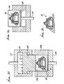
- Figure 4 is an enlarged section showing details of a wear resistant skin or layer in a body means receiving and mounting a tungsten carbide insert;
- Figures 5a and 5b are elevations showing different forms of inserts; and
- Figures 6a and 6b are sections showing modified cutter constructions; and
- Figures 7a to 7h show detailed process steps.
- In Figure 1, the illustrated improved
roller bit cutter 10 incorporating the invention includes a tough, metallic, generally conical and fractureresistant core 11. The core has ahollow interior 12, and defines acentral axis 13 of rotation. The bottom of the core is tapered at 14, and the interior includes multiplesuccessive zones 12a, 12b, 12c, 12d, 12e and 12f,concentri6:toaxis 13, as shown. An annular metallic radial (sleeve type) bearinglayer 15 is carried by the core at interior zone 12a to support the core for rotation.Layer 15 is attached to annular surface-lla of the core, and extends aboutaxis 13. It consists of a bearing alloy, as will appear. - An impact and wear resistant metallic
inner layer 16 is attached to the core at its interior zones 12b - 12f, to provide an axial thrust bearing; as at end surface 16a. A plurality of hard metallic inserts 17, as for example of tungsten carbide, haveinner anchor portions 17a carried by the core to be partly embedded or received incore recesses 18. The inserts also have portions 17b that protrude outwardly, as shown, to define cutters (see also Figures 4, 5a and 5b), at least some of the inserts spaced aboutaxis 13. One insert 17' may be located at the extreme outer end of the core, ataxis 13. - Finally, a wear resistant outer metallic skin or
layer 19 is on and attached to the core exterior surface, to extend completely over that surface including the surfaces of the core portions that define therecesses 18, whereby the inserts are in fact attached to thelayer portions 19a in those recesses. - Preferably, at least one or two of the
layers interior core section 11. Similarly, layers 16 and 19 should be different than 15, and even 16 should differ from 19. Each of these layers and thecore piece 11 may, therefore, be manufactured separately or applied in place as powder mixtures prior to cold pressing. Thus, there may be a number of possible processing schemes as indicated by arrows in Figure 3. The encircled numbers in this figure refer to the possible processing steps (or operations) listed in below Table 1. Each continuous path in the figure, starting from Step No. 1 and ending at Step No. 15, defines a separate processing scher.e which, when followed, is capable of producing integrally consolidate composite conical cutters.


- The processing schemes outlined, include only the major steps involved in the flow of processing operations. Other secondary operations that are routinely used in most processing schemes for similarly manufactured products, are not included for sake of simplicity. These may be cleaning, manual patchwork to repair small defects, grit blasting to remove loose particles or oxide scale, dimensional or structural inspections etc.
- All of the processing steps are unique, as may easily be recognised by those who are familiar with the metallurgical arts in the powder metals processing field. Each provides a number of benefits from the processing point of view, and some of which are listed as follows:
- (1) All assembly operations; i.e. painting, spraying. placing, etc., in preparing the composite cutter structure for the hot-pressing operation (Step No. 12 in Table 1) are performed at or near room temperature. Thus, problems associated with thermal property differences or low strenght, unconsolidated state of the composite cone prior to hot densification, are avoided. Repair work, geometrical or dimensional control, and in-process handling are greatly simplified.
- (2) Application of powdered metal or alloy or metal compound surface layers, using volatile binders, such cellulose acetate, corn starch and various distilled products, provide sturdy powder layers strongly held together by the binding agent, thus adding to the green strength of the total unconsolidated cone structure. This makes it easy to control suface layer thickness, handling of the assembly in processing and provides mechanical support for the TCI's.
- (3) Low temperature application of afore-mentioned surface layers avoids pitfalls associated with high temperature spraying of powders, as promoted by Nederveen (6) et al. As is well known, thermally-sprayed metal powders incorporate oxides into the sprayed layers. Oxide particles in surface layers may act as structural discontinuities or notches, thus weakening the part.
- (4) The proposed schemes in every case produce a near- net-shape product, greatly reducing the labour-intensive machining operations required in the conventional conical cutter production.
- (5) The consolidation of various components of the cone, after applying them in powder or insert form, allows the use of inserts having non-parallel side surfaces, as illustrated in Figure 5b (see
insert 370 with bottom portions 370a to be received in the cone recesses). This provides, in the finished product, a greatly increased support for each insert, practically eliminating in-service pull-out. In addition, the structural integrity thus provided for the inserts allows insert extensions substantially more than is otherwise. Further benefits in insert wear mode and increased rate of penetration into the rock formation can be achieved with one portion of the insert being longer than the other as shown in Figure 5b, where A'B' is longer than AB. - Various sections of the cone cross-section have been identified in Figure 1, each requiring different engineering properties to best function in service. Consequently, materials for each section should be selected separately.
-
Interior core piece 11 should be made of an alloy possessing high strength and toughness, and preferably requiring thermal treatments below 1700°F (to reduce damage due to cooling stresses) to impart its desired mechanical properties. Such restrictions can be met by the following classes of materials: - (1) Hardening grades of low-alloy steels (ferrous base) with carbon contents ranging nominally between 0.1 and 0.65%, manganese 0.01 to 2.0%, silicon 0.01 to 2.2%, nickel 0.4 to 3.75%, chromium 0.01 to 1.2%, molybdenum 0.15 to 0.40%, copper to 0.3% and remainder substantially iron, total of all other elements to be less than 1.0% by weight.
- (2) Castable alloy steel having less than 8% total alloying element content; most typically ASTM-A148-80 grades.
- (3) Ultra-high strength steels most specifically known in the industry as: D-6A, H-11, 9Ni-4Co, 18-Ni maraging, 300-M, 4130, 4330 V, 4340. These steels norinally have the same levels of C, Mn and Si as do the low-alloy steels described in (1) above. However, they have higher contents of other alloying elements: chromium up to 5.0%, nickel to 19.0%, molybdenum to 5.0%, vanadium to 1.0%, cobalt to 8.0%, with remaining substantially iron, and all other elements totalling less than 1.0%.
- (4) (Ferrous) powder metal steels with nominal chemistries falling within: 79 to 98% iron, 0-20% copper, 0.4 to 1.0% carbon, and 0-4.0% nickel.
- (5) Age hardenable and martensitic stainless steels whose compositions fall into the limits described in (3) above, except that they may have chromium up to 20%, aluminium up to 2.5%, titanium up to 1.5%, copper up - to 4.0%, and columbium plus tantalum up to 0.5%.
- In all cases, the core piece mechanical properties should exceed the following:
- 130 ksi ultimate tensile strength
- 80 ksi yield strength
- 5% tensile elongation
- 15% reduction in area
- 10 ft-lb (izod) impact strength
- Wear resistant
exterior skin 19, which may have a thickness within 0.01 to 0.20 inch range, need not be uniform in thickness. This layer of hard wear-resistant material may, indeed, have islands of "inserts" whose thickness, composition, as well as shape, may be quite different than those of the remaining "skin". Materials suitable for the cone skin include: - (1) A composite mixture of particles of refractory hard compounds in a binding metal or alloy where the refractory hard compounds have a micro-hardness of higher than 1,000 kg/mm2 (50-100 g testing load), and a melting point of 1600°C or higher in their commercially pure forms, and where the binding metal or alloy may be those based on iron, nickel, cobalt or copper.
- Examples of such refractory hard compounds include carbides, oxides, nitrides and borides (or their mixtures) of elements Ti, W, Al, V, Zr, Cr, Mo, Ta, Nb and Hf.
- (2) Speciality tool steels, readily available in powder form, having large amounts of strong carbine formers such as Ti, V, Mb, Mo, W and Cr, and a carbon content higher than 2.0% by weight.
- (3) Hardfacing alloys based on transition elements Fe, Ni or Co, with the following general chemistry ranges:


- (4) Wear -resistant intermetallic (Lave phase) materials based on cobalt or nickel as the primary constituent and having molybdenum (25 - 35%), chromium (8 - 18%), silicon (2 - 4%) and carbon 0.08% maximum.
- Thrust-bearing 16 may be similar in composition to the
exterior skin 19. in addition, when they are incorporated into the cone as inserts (pre-formed, separately processed cast, wrought or powder metal-produced shapes), they may be made of any metal or alloy having a hardness above 35 R . They may, in such cases, have a composite structure where part of the structure is a lubricating material such as molybdenum disulfide, tin, copper, silver, lead or their alloys, or graphite. - Cobalt-cemented Tungsten carbide Inserts (TCI's), 17 in Figure 1, are to be readily available cobalt-tungsten carbide compositions whose cobalt content usually is within the 5 -18% range.
-
Bearing alloy 15, if incorporated into the cone as a separately-manufactured insert, may either be a hardened or carburized or nitrided or borided steel or any one of a number of readily available commercial non-ferrous bearing alloys, such as the bronzes. If the bearing 1s weld deposited, the material may still be a bronze. If, however, the.bearing is integrally hot pressed in place from a previously applied powder, or if the insert is produced by any of the known powder metallurgy techniques, then it may also have a composite structure having dispersed within it a phase containing lubricating properties to the bearing. - The cone configuration accords with the journal pin shape and is affected by the interaction of the cone with the other cones of the same bit. While configuration may vary somewhat, there are certain configurations associated with the cone sections identified as 11, 15, 16, 17 and 19 which are unusually advantageous, and are listed as follows:
- (1) Extension of the wear-resistant
alloy skin layer 19 into the clearance between the walls of the blind end hole or recess incore piece 11, as well as the configuration of theinsert 170 in Figure 4 and having anon-parallel anchor portion 170a. - (2) Non-parallel sided inserts or TCI's, where the cross- sectional area at A-A' in Figure 5b is smaller than that at the bottom of the
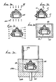
TCI 370. Note anchor portion 370a. In addition, cross-sections on planes parallel to the bottom surface of the TCI need not be a circle, as customary, but may be any shape other than a circle; i.e. elliptical, irregular, polygonal, etc., and sides may not be equal in length. - (3)- Thrust-bearing
layer 16 may or may not be a single piece insert or a continuously applied powder metal layer. Indeed, this layer may be made up of several inserts 160-162 most likely to be circular in shape as indicated in Figure 6(a), or a combination of inserts andpowdered metal layer 40 as exemplified in Figure 6(b). EXAMPLES - A typical processing route involves the steps numbered 1, 3, 5, 6, 7, 10, 11, 12 and 15 in Table 1. A low alloy steel composition is blended to form a powder mixture of composition suitable for the core. In one instance, this mixture constituted an alloy having the following final analysis: 0.22% manganese, 0.23% molybdenum, 1.84% nickel, 0.27% carbon and remainder substantially iron. The powder was cold pressed to a preform and sintered at 2050°F for one hour in a reducing furnace atmosphere. Carbide inserts were placed in the blind holes created in the preform and the exterior of the cone was painted with a slurry containing hardfacing metal powder, Stellite No. 1, making sure the slurry filled all clearance space between the carbide insert and the preform.
- The slurry was prepared by mixing Stellite powder with 3% cellulose acetate powder and adding sufficient amount of acetone to develop the desired slurry fluidity. The Stellite No. 1 alloy powder had a nominal chemistry (in weight percent) of: 30% chromium, 2.5% carbon, 1% silicon, 12.5% tungsten, 1% maximum each of manganese and molybdenum, and 3% maximum each of iron and nickel, with remainder being substantially cobalt. Once applied, the outer skin formed on the core piece quickly dried at room temperature.
- A thin layer of a thrust bearing alloy was similarly applied on surfaces identified by 16 in Figure 1. The composition of this layer was the same as the exterior skin applied over the core piece. A radial bearing alloy tube segment was then fitted within the cylindrical section identified as 15 in Figure 1. The AISI 105 carbon steel tube having 0.1 inch wall thickness was fixed in place by placing it on a thin layer of slurry applied core piece alloy steel powder.
- The preform assembly, thus prepared, was dried in an oven at 100°F for overnight, driving away all volatile constituents of the slurries. It was then induction heated to 2250°F in less than 4 minutes and immersed in hot ceramic grain, which was also at 2250°F, within a cylindrical die. A pressure of 40 tons per square inch was applied, by way of a hydraulic press, onto the grain which transmitted the pressure, in various degrees, to the preform in all directions. The peak press pressure of 40 tsi was reached within 4 - 5 seconds and the peak pressure was maintained for less than 2 seconds and released. The die contents when emptied separated into grain and the consolidated conical cutter. Before the part had a chance to cool below 1600°F it was transferred to-a furnace operating at 1565°F, kept there for an hour and oil quenched. To prevent oxidation, the furnace atmosphere was adjusted to be a reducing atmosphere, e.g. cracked ammonia. The hardened part was then tempered for one hour at 1000°F and air cooled to assure
- A similarly processed tensile test bar when tensile tested exhibited 152 ksi ultimate tensile strength, 141 ksi yield strength, 12% elongation and 39% reduction of area. Another test bar which was processed in the same manner as above, except tempered at 450°F, exhibited 215 ksi ultimate tensile strength, 185 ksi yield strength, 7% elongation and 21% reduction of area. Thus, one may easily develop a desired set of mechanical properties in the consolidated core piece by tempering a selected temperature.
- In another example, powder slurry for the wear resistant exterior skin and the thrust bearing surface was prepared using a 1.5% by weight mixture of cellulose acetate with Stellite alloy No. 1 powder. This preform was dried at 250°F for two hours instead of 100°F for overnight and the remaining processing steps were identical to the above example. No visible differences were detected between the two parts produced by the two experiments.
- In yet another example, radial bearing alloy was affixed to the interior wall of the core through the use of a nickel powder slurry similarly prepared as above. -Once again the bond between the radial bearing alloy and the core piece was extremely strong as determined by separately conducted bonding experiments.
- The term "composite" is used both in the microstructural sense or form an engineering sense, whichever is more appropriate. Thus, a material made up of discrete fine phase(s) dispersed within another phase is considered a composite of phases, while a structure made up of discrete, relatively large regions joined or assembled by some means, together is also considered a "composite". An alloy layer composed of a mixture of carbide particles in cobalt, would micro-structurally be a composite layer, while a cone cutter composed of various distinct layers, TCl's and other inserts, would be a composite part as well.
- The term "green" in Table 1,
line 2, refers to a state where the powder metal part is not yet fully densified, but has sufficient strength to be handled without chipping or breakage. Sintering, (the same table, line 3) is a process by which powdered (or otherwise) material is put in intimate contact and heated to cause a metallurgical bond between them. - This invention introduces, for the first time, the following novel features to a TCI drill bit cone:
- (1) a "high temperature - short heating cycle" means of consolidation of a composite cone into a nearly finished product, saving substantial labour time and allowing the use of multiple materials tailored to meet localised demands on'their properties.
- (2) Various material layers are applied at or near room temperature, thus eliminating damage that would otherwise be occurring if a thermally-activated process was used.
- (3) Unlike hot isostatic pressing (HIP) inside an autoclave pressurised by gas, the hot pressing, as described herein, requires only a short time at high consolidation temperatures. This is partially due to the fact that rapid heating techniques most particularly usuable in hot pressing, may be not suitable for heating inside an autoclave. This is a major advantage for the hot pressing process, whereby bonding of discrete particles takes place quickly (few minutes) without unwanted diffusion reactions. Thus, consolidation of a composite part, such as the conical cutter, is accomplished without any side effects, whereas in HIP, processing cycle takes up to 20 ... sometimes 30 hours, mostly at high temperatures. Diffusion of such elements as carbon from the carbides, for example, then creates metallurgical problems of structural integrity. In the absence of such fears, as in the present method, the conical cutters have superior properties and superior field performance, and furthermore no diffusion barrier layer between the carbides and the cone material would be necessary.
- (4) The use of non-parallel sided inserts.
- (5) The use of a hard wear-resistant exterior layer, for example painted on cold, the same hard layer surrounding and locking the TCI in place after hot consolidation. The latter feature greatly simplifies the method of application of the exterior layer.
- (6) Provision of lubricious inserts or insert, plus powder metal layers providing the thrust-bearing surface layer.
- (7) Elimination of lengthy surface hardening processes such as carburizing.
- (8) Vastly increased freedom of selection of materials.
- (9) Increased freedom to extend the TCI's further outward for more aggressive cutting of the-rock.
- Figure 2 shows the
conical bit cutter 10 of the invention applied to thejournal pin 50 on abit body 51, having a threadedstem 52.Pin 50 also provides aball bearing race 53 adapted to register withrace surface 20 about zone 12b, and journal bearing 54 adapted to mountlayer 15 as described. -
Step 3 of the process as listed in Table I is for example shown in Figure 7a, thearrows 100 and 101 indicating isostatic pressurisation of both interior and exterior surfaces of thecore piece 11. Pressure application is effected for example by the use of rubber moulds or ceramic granules packed about the core, and pressurised. Blind holes are shown at 103. Steps 5 - 10 of the Table I process are indicated in Figure 7b.Step 11 of the process is exemplified by the induction heating step of Figure 7c. - In Figure 7d, the hot part (cone, as in Figure 1) is indicated at 99 as embedded in hot
ceramic grain 106, in shuttle die 107. The latter is then introduced into a press die 108 (see Figure 7e), and theouter wall 107a of the shuttle die is upwardly removed. Die 108 hascylindrical wall 108a and bottom wall 108b. Figure 7f is like Figure 7e, but shows aplunger 109 applying force to thegrain 106, in response to fluid pressure application at 110 to the plunger viaactuator cylinder 111. This corresponds to step 12 of the Table I process. In Figure 7g thepart 99 andgrain 106 are upwardly ejected by asecond plunger 112 elevating thebottom wall 107. - In Figure 7g, the grain is removed from the
part 106 and is recycled to step 7d. The consolidated part including its component may then be finished, as by grit blasting, finish machining and grinding, and inspected. SeeStep 15 of Table 1.
Claims (21)


Priority Applications (1)
| Application Number | Priority Date | Filing Date | Title |
|---|---|---|---|
| AT85305165T ATE42376T1 (en) | 1984-07-23 | 1985-07-19 | CONICAL CUTTING HEAD FOR DRILL BIT AND METHOD OF ITS MANUFACTURE. |
Applications Claiming Priority (2)
| Application Number | Priority Date | Filing Date | Title |
|---|---|---|---|
| US06/633,635 US4597456A (en) | 1984-07-23 | 1984-07-23 | Conical cutters for drill bits, and processes to produce same |
| US633635 | 1984-07-23 |
Publications (3)
| Publication Number | Publication Date |
|---|---|
| EP0169718A2 true EP0169718A2 (en) | 1986-01-29 |
| EP0169718A3 EP0169718A3 (en) | 1987-01-21 |
| EP0169718B1 EP0169718B1 (en) | 1989-04-19 |
Family
ID=24540463
Family Applications (1)
| Application Number | Title | Priority Date | Filing Date |
|---|---|---|---|
| EP85305165A Expired EP0169718B1 (en) | 1984-07-23 | 1985-07-19 | Conical cutters for drill bits and processes to produce same |
Country Status (8)
| Country | Link |
|---|---|
| US (1) | US4597456A (en) |
| EP (1) | EP0169718B1 (en) |
| JP (1) | JPS6160988A (en) |
| AT (1) | ATE42376T1 (en) |
| CA (1) | CA1238630A (en) |
| DE (1) | DE3569595D1 (en) |
| MX (1) | MX166060B (en) |
| SG (1) | SG106391G (en) |
Cited By (5)
| Publication number | Priority date | Publication date | Assignee | Title |
|---|---|---|---|---|
| EP0247255A1 (en) * | 1985-01-07 | 1987-12-02 | Ceracon, Inc. | Pump liners and a method of cladding the same |
| AU2004205106B2 (en) * | 2003-08-13 | 2007-01-04 | Sandvik Intellectual Property Ab | Shaped inserts with increased retention force |
| GB2438855A (en) * | 2006-06-10 | 2007-12-12 | Reedhycalog Uk Ltd | Asymmetric cutting element |
| WO2008073308A3 (en) * | 2006-12-07 | 2008-07-31 | Baker Hughes Inc | Displacement members and methods of using such displacement members to form bit bodies of earth boring rotary drills bits |
| EP2821166A1 (en) * | 2013-07-04 | 2015-01-07 | Sandvik Intellectual Property AB | A method for manufacturing a wear resistant component comprising mechanically interlocked cemented carbide bodies |
Families Citing this family (68)
| Publication number | Priority date | Publication date | Assignee | Title |
|---|---|---|---|---|
| US4679640A (en) * | 1986-02-21 | 1987-07-14 | Dresser Industries, Inc. | Method for case hardening rock bits and rock bits formed thereby |
| US4832139A (en) * | 1987-06-10 | 1989-05-23 | Smith International, Inc. | Inclined chisel inserts for rock bits |
| US4853178A (en) * | 1988-11-17 | 1989-08-01 | Ceracon, Inc. | Electrical heating of graphite grain employed in consolidation of objects |
| US4933140A (en) * | 1988-11-17 | 1990-06-12 | Ceracon, Inc. | Electrical heating of graphite grain employed in consolidation of objects |
| US5294382A (en) * | 1988-12-20 | 1994-03-15 | Superior Graphite Co. | Method for control of resistivity in electroconsolidation of a preformed particulate workpiece |
| US4915605A (en) * | 1989-05-11 | 1990-04-10 | Ceracon, Inc. | Method of consolidation of powder aluminum and aluminum alloys |
| US5279374A (en) * | 1990-08-17 | 1994-01-18 | Sievers G Kelly | Downhole drill bit cone with uninterrupted refractory coating |
| US5032352A (en) * | 1990-09-21 | 1991-07-16 | Ceracon, Inc. | Composite body formation of consolidated powder metal part |
| GB2276886B (en) * | 1993-03-19 | 1997-04-23 | Smith International | Rock bits with hard facing |
| US5421423A (en) * | 1994-03-22 | 1995-06-06 | Dresser Industries, Inc. | Rotary cone drill bit with improved cutter insert |
| US5452771A (en) * | 1994-03-31 | 1995-09-26 | Dresser Industries, Inc. | Rotary drill bit with improved cutter and seal protection |
| US5429200A (en) * | 1994-03-31 | 1995-07-04 | Dresser Industries, Inc. | Rotary drill bit with improved cutter |
| US5615747A (en) * | 1994-09-07 | 1997-04-01 | Vail, Iii; William B. | Monolithic self sharpening rotary drill bit having tungsten carbide rods cast in steel alloys |
| US6547017B1 (en) | 1994-09-07 | 2003-04-15 | Smart Drilling And Completion, Inc. | Rotary drill bit compensating for changes in hardness of geological formations |
| US5492186A (en) * | 1994-09-30 | 1996-02-20 | Baker Hughes Incorporated | Steel tooth bit with a bi-metallic gage hardfacing |
| US5663512A (en) * | 1994-11-21 | 1997-09-02 | Baker Hughes Inc. | Hardfacing composition for earth-boring bits |
| US5755299A (en) * | 1995-08-03 | 1998-05-26 | Dresser Industries, Inc. | Hardfacing with coated diamond particles |
| SE506178C2 (en) * | 1996-01-22 | 1997-11-17 | Sandvik Ab | Friction welded product for rock drilling as well as process for manufacturing the product |
| US5743033A (en) * | 1996-02-29 | 1998-04-28 | Caterpillar Inc. | Earthworking machine ground engaging tools having cast-in-place abrasion and impact resistant metal matrix composite components |
| US5755301A (en) * | 1996-08-09 | 1998-05-26 | Dresser Industries, Inc. | Inserts and compacts with lead-in surface for enhanced retention |
| US5871060A (en) * | 1997-02-20 | 1999-02-16 | Jensen; Kenneth M. | Attachment geometry for non-planar drill inserts |
| US5967248A (en) | 1997-10-14 | 1999-10-19 | Camco International Inc. | Rock bit hardmetal overlay and process of manufacture |
| US6102140A (en) * | 1998-01-16 | 2000-08-15 | Dresser Industries, Inc. | Inserts and compacts having coated or encrusted diamond particles |
| US6170583B1 (en) | 1998-01-16 | 2001-01-09 | Dresser Industries, Inc. | Inserts and compacts having coated or encrusted cubic boron nitride particles |
| US6138779A (en) * | 1998-01-16 | 2000-10-31 | Dresser Industries, Inc. | Hardfacing having coated ceramic particles or coated particles of other hard materials placed on a rotary cone cutter |
| WO2000034002A1 (en) * | 1998-12-04 | 2000-06-15 | Halliburton Energy Services, Inc. | Method for applying hardfacing material to a steel bodied bit and bit formed by such a method |
| CA2345758C (en) * | 2000-05-01 | 2006-02-21 | Smith International, Inc. | Rotary cone bit with functionally engineered composite inserts |
| SE521488C2 (en) * | 2000-12-22 | 2003-11-04 | Seco Tools Ab | Coated cutting with iron-nickel-based bonding phase |
| JP4282284B2 (en) * | 2001-08-22 | 2009-06-17 | 株式会社小松製作所 | Track |
| US6772849B2 (en) * | 2001-10-25 | 2004-08-10 | Smith International, Inc. | Protective overlay coating for PDC drill bits |
| US7044243B2 (en) * | 2003-01-31 | 2006-05-16 | Smith International, Inc. | High-strength/high-toughness alloy steel drill bit blank |
| US20050211475A1 (en) | 2004-04-28 | 2005-09-29 | Mirchandani Prakash K | Earth-boring bits |
| US9428822B2 (en) | 2004-04-28 | 2016-08-30 | Baker Hughes Incorporated | Earth-boring tools and components thereof including material having hard phase in a metallic binder, and metallic binder compositions for use in forming such tools and components |
| US20060210826A1 (en) * | 2005-03-21 | 2006-09-21 | Wu James B C | Co-based wire and method for saw tip manufacture and repair |
| US20060237236A1 (en) * | 2005-04-26 | 2006-10-26 | Harold Sreshta | Composite structure having a non-planar interface and method of making same |
| US8637127B2 (en) | 2005-06-27 | 2014-01-28 | Kennametal Inc. | Composite article with coolant channels and tool fabrication method |
| US7703555B2 (en) * | 2005-09-09 | 2010-04-27 | Baker Hughes Incorporated | Drilling tools having hardfacing with nickel-based matrix materials and hard particles |
| US8002052B2 (en) | 2005-09-09 | 2011-08-23 | Baker Hughes Incorporated | Particle-matrix composite drill bits with hardfacing |
| US7997359B2 (en) * | 2005-09-09 | 2011-08-16 | Baker Hughes Incorporated | Abrasive wear-resistant hardfacing materials, drill bits and drilling tools including abrasive wear-resistant hardfacing materials |
| US7597159B2 (en) | 2005-09-09 | 2009-10-06 | Baker Hughes Incorporated | Drill bits and drilling tools including abrasive wear-resistant materials |
| MX2008012771A (en) | 2006-04-27 | 2008-11-28 | Tdy Ind Inc | Modular fixed cutter earth-boring bits, modular fixed cutter earth-boring bit bodies, and related methods. |
| US7343990B2 (en) * | 2006-06-08 | 2008-03-18 | Baker Hughes Incorporated | Rotary rock bit with hardfacing to reduce cone erosion |
| RU2009111383A (en) * | 2006-08-30 | 2010-10-10 | Бейкер Хьюз Инкорпорейтед (Us) | METHODS FOR APPLICATION OF WEAR-RESISTANT MATERIAL ON EXTERNAL SURFACES OF DRILLING TOOLS AND RELATED DESIGNS |
| BRPI0717332A2 (en) | 2006-10-25 | 2013-10-29 | Tdy Ind Inc | ARTICLES HAVING ENHANCED RESISTANCE TO THERMAL CRACK |
| US8790439B2 (en) | 2008-06-02 | 2014-07-29 | Kennametal Inc. | Composite sintered powder metal articles |
| US20100000798A1 (en) * | 2008-07-02 | 2010-01-07 | Patel Suresh G | Method to reduce carbide erosion of pdc cutter |
| US8025112B2 (en) | 2008-08-22 | 2011-09-27 | Tdy Industries, Inc. | Earth-boring bits and other parts including cemented carbide |
| US8272816B2 (en) | 2009-05-12 | 2012-09-25 | TDY Industries, LLC | Composite cemented carbide rotary cutting tools and rotary cutting tool blanks |
| US8201610B2 (en) | 2009-06-05 | 2012-06-19 | Baker Hughes Incorporated | Methods for manufacturing downhole tools and downhole tool parts |
| US8308096B2 (en) | 2009-07-14 | 2012-11-13 | TDY Industries, LLC | Reinforced roll and method of making same |
| MX340467B (en) | 2010-05-20 | 2016-07-08 | Baker Hughes Incorporated * | METHODS TO FORM AT LEAST A PORTION OF TOOLS TO DRILL THE EARTH AND ITEMS FORMED BY SUCH METHODS. |
| EP2571646A4 (en) | 2010-05-20 | 2016-10-05 | Baker Hughes Inc | METHODS OF FORMING AT LEAST ONE PART OF LAND DRILLING TOOLS |
| MX2012013455A (en) | 2010-05-20 | 2013-05-01 | Baker Hughes Inc | METHODS TO FORM AT LEAST A PORTION OF TOOLS TO DRILL THE EARTH AND ITEMS FORMED BY SUCH METHODS. |
| US9624730B2 (en) | 2010-12-01 | 2017-04-18 | Vermeer Manufacturing Company | Hard facing configuration for a drilling tool |
| US8733475B2 (en) | 2011-01-28 | 2014-05-27 | National Oilwell DHT, L.P. | Drill bit with enhanced hydraulics and erosion-shield cutting teeth |
| US8607899B2 (en) | 2011-02-18 | 2013-12-17 | National Oilwell Varco, L.P. | Rock bit and cutter teeth geometries |
| BR112013027545A2 (en) | 2011-04-26 | 2017-01-10 | Smith International | cutting element, and method for forming a drill bit |
| WO2012149086A2 (en) | 2011-04-26 | 2012-11-01 | Smith International, Inc. | Polycrystalline diamond compact cutters with conic shaped end |
| US8961019B2 (en) | 2011-05-10 | 2015-02-24 | Smith International, Inc. | Flow control through thrust bearing assembly |
| US8800848B2 (en) | 2011-08-31 | 2014-08-12 | Kennametal Inc. | Methods of forming wear resistant layers on metallic surfaces |
| US9016406B2 (en) | 2011-09-22 | 2015-04-28 | Kennametal Inc. | Cutting inserts for earth-boring bits |
| US9249628B2 (en) | 2012-11-16 | 2016-02-02 | National Oilwell DHT, L.P. | Hybrid rolling cone drill bits and methods for manufacturing same |
| US9140071B2 (en) | 2012-11-26 | 2015-09-22 | National Oilwell DHT, L.P. | Apparatus and method for retaining inserts of a rolling cone drill bit |
| US9163660B1 (en) * | 2013-01-08 | 2015-10-20 | Us Synthetic Corporation | Bearing assemblies, apparatuses, and motor assemblies using the same |
| US20170044859A1 (en) * | 2015-08-10 | 2017-02-16 | Tyler W. Blair | Slip Element and Assembly for Oilfield Tubular Plug |
| US11938572B2 (en) * | 2019-11-08 | 2024-03-26 | Att Technology, Ltd. | Method for low heat input welding on oil and gas tubulars |
| CN116287935A (en) * | 2023-03-18 | 2023-06-23 | 西南石油大学 | A kind of preparation method of alloy material for drill bit |
| US12480366B1 (en) | 2024-07-18 | 2025-11-25 | Kennametal Inc. | Earth cutting tool, earth cutting device, and related methods |
Family Cites Families (26)
| Publication number | Priority date | Publication date | Assignee | Title |
|---|---|---|---|---|
| US3310870A (en) * | 1967-03-28 | Process for producing nickel-coated steel | ||
| GB449974A (en) * | 1935-04-29 | 1936-07-08 | John Corstorphine | An improved boring and drilling tool |
| US2833520A (en) * | 1957-01-07 | 1958-05-06 | Robert G Owen | Annular mill for use in oil wells |
| US3235316A (en) * | 1963-04-22 | 1966-02-15 | Hughes Tool Co | Journal bearing with alternating surface areas of wear resistant and antigalling materials |
| US3453849A (en) * | 1965-10-13 | 1969-07-08 | Texas Instruments Inc | Manufacture of clad metals |
| US3800891A (en) * | 1968-04-18 | 1974-04-02 | Hughes Tool Co | Hardfacing compositions and gage hardfacing on rolling cutter rock bits |
| US3721307A (en) * | 1971-04-27 | 1973-03-20 | Murphy Ind Inc | Drill bit bearings |
| US3823030A (en) * | 1972-10-18 | 1974-07-09 | Dresser Ind | Method of making a bearing system having entrained wear-resistant particles |
| US3984158A (en) * | 1973-09-10 | 1976-10-05 | Dresser Industries, Inc. | Journal and pilot bearings with alternating surface areas of wear resistant and anti-galling materials |
| US3995917A (en) * | 1973-11-23 | 1976-12-07 | Smith International, Inc. | Aluminum bronze bearing |
| US4108692A (en) * | 1975-01-13 | 1978-08-22 | Smith International, Inc. | Rock bit roller cutter and method therefor |
| US3990751A (en) * | 1975-08-13 | 1976-11-09 | Reed Tool Company | Drill bit |
| NL7703234A (en) * | 1977-03-25 | 1978-09-27 | Skf Ind Trading & Dev | METHOD FOR MANUFACTURING A DRILL CHUCK INCLUDING HARD WEAR-RESISTANT ELEMENTS, AND DRILL CHAPTER MADE ACCORDING TO THE METHOD |
| US4173457A (en) * | 1978-03-23 | 1979-11-06 | Alloys, Incorporated | Hardfacing composition of nickel-bonded sintered chromium carbide particles and tools hardfaced thereof |
| US4172395A (en) * | 1978-08-07 | 1979-10-30 | Dresser Industries, Inc. | Method of manufacturing a rotary rock bit |
| JPS5526271A (en) * | 1978-08-17 | 1980-02-25 | Toray Industries | Production of hygh grade fabric |
| JPS5625594A (en) * | 1979-08-06 | 1981-03-11 | Tone Boring Co | Tricoen bit and its manufacture |
| NL7908745A (en) * | 1979-12-04 | 1981-07-01 | Skf Ind Trading & Dev | METHOD FOR MANUFACTURING AN ARTICLE APPLIED BY THERMAL SPRAYING AND OBJECT, IN PARTICULAR A DRILLING CHISEL, OBTAINED BY THIS METHOD |
| DE3030010C2 (en) * | 1980-08-08 | 1982-09-16 | Christensen, Inc., 84115 Salt Lake City, Utah | Rotary drill bit for deep drilling |
| US4484644A (en) * | 1980-09-02 | 1984-11-27 | Ingersoll-Rand Company | Sintered and forged article, and method of forming same |
| US4368788A (en) * | 1980-09-10 | 1983-01-18 | Reed Rock Bit Company | Metal cutting tools utilizing gradient composites |
| SE423562B (en) * | 1980-11-13 | 1982-05-10 | Cerac Inst Sa | PROCEDURE FOR PREPARING A STABLE BODY INCLUDING HARD MATERIAL INSTALLATIONS |
| US4365679A (en) * | 1980-12-02 | 1982-12-28 | Skf Engineering And Research Centre, B.V. | Drill bit |
| US4396077A (en) * | 1981-09-21 | 1983-08-02 | Strata Bit Corporation | Drill bit with carbide coated cutting face |
| EP0111600A1 (en) * | 1982-12-13 | 1984-06-27 | Reed Rock Bit Company | Improvements in or relating to cutting tools |
| DE3478627D1 (en) * | 1983-10-24 | 1989-07-13 | Smith International | Rock bit cutter cones having metallurgically bonded cutter inserts |
-
1984
- 1984-07-23 US US06/633,635 patent/US4597456A/en not_active Expired - Lifetime
-
1985
- 1985-06-27 CA CA000485459A patent/CA1238630A/en not_active Expired
- 1985-07-19 AT AT85305165T patent/ATE42376T1/en not_active IP Right Cessation
- 1985-07-19 DE DE8585305165T patent/DE3569595D1/en not_active Expired
- 1985-07-19 EP EP85305165A patent/EP0169718B1/en not_active Expired
- 1985-07-23 JP JP60162782A patent/JPS6160988A/en active Granted
- 1985-07-26 MX MX0206103A patent/MX166060B/en unknown
-
1991
- 1991-12-14 SG SG1063/91A patent/SG106391G/en unknown
Cited By (9)
| Publication number | Priority date | Publication date | Assignee | Title |
|---|---|---|---|---|
| EP0247255A1 (en) * | 1985-01-07 | 1987-12-02 | Ceracon, Inc. | Pump liners and a method of cladding the same |
| US4715313A (en) * | 1985-01-07 | 1987-12-29 | Cdp, Ltd. | Pump liners and a method of cladding the same |
| US4746554A (en) * | 1985-01-07 | 1988-05-24 | Cdp, Ltd. | Pump liners and a method of cladding the same |
| AU2004205106B2 (en) * | 2003-08-13 | 2007-01-04 | Sandvik Intellectual Property Ab | Shaped inserts with increased retention force |
| US7416035B2 (en) | 2003-08-13 | 2008-08-26 | Smith International, Inc. | Shaped inserts with increased retention force |
| GB2438855A (en) * | 2006-06-10 | 2007-12-12 | Reedhycalog Uk Ltd | Asymmetric cutting element |
| WO2008073308A3 (en) * | 2006-12-07 | 2008-07-31 | Baker Hughes Inc | Displacement members and methods of using such displacement members to form bit bodies of earth boring rotary drills bits |
| EP2821166A1 (en) * | 2013-07-04 | 2015-01-07 | Sandvik Intellectual Property AB | A method for manufacturing a wear resistant component comprising mechanically interlocked cemented carbide bodies |
| WO2015001006A3 (en) * | 2013-07-04 | 2015-03-19 | Sandvik Intellectual Property Ab | A method for manufacturing a wear resistant component comprising mechanically interlocked cemented carbide bodies |
Also Published As
| Publication number | Publication date |
|---|---|
| EP0169718A3 (en) | 1987-01-21 |
| JPS6160988A (en) | 1986-03-28 |
| DE3569595D1 (en) | 1989-05-24 |
| JPH0228676B2 (en) | 1990-06-26 |
| SG106391G (en) | 1992-02-14 |
| ATE42376T1 (en) | 1989-05-15 |
| CA1238630A (en) | 1988-06-28 |
| EP0169718B1 (en) | 1989-04-19 |
| MX166060B (en) | 1992-12-16 |
| US4597456A (en) | 1986-07-01 |
Similar Documents
| Publication | Publication Date | Title |
|---|---|---|
| EP0169718B1 (en) | Conical cutters for drill bits and processes to produce same | |
| US4562892A (en) | Rolling cutters for drill bits | |
| US4592252A (en) | Rolling cutters for drill bits, and processes to produce same | |
| US4554130A (en) | Consolidation of a part from separate metallic components | |
| US4630692A (en) | Consolidation of a drilling element from separate metallic components | |
| US4593776A (en) | Rock bits having metallurgically bonded cutter inserts | |
| US12186807B2 (en) | Heterogeneous composite bodies with isolated cermet regions formed by high temperature, rapid consolidation | |
| US4907665A (en) | Cast steel rock bit cutter cones having metallurgically bonded cutter inserts | |
| US4398952A (en) | Methods of manufacturing gradient composite metallic structures | |
| US4372404A (en) | Cutting teeth for rolling cutter drill bit | |
| US4368788A (en) | Metal cutting tools utilizing gradient composites | |
| US9109413B2 (en) | Methods of forming components and portions of earth-boring tools including sintered composite materials | |
| US4683781A (en) | Cast steel rock bit cutter cones having metallurgically bonded cutter inserts, and process for making the same | |
| US20060159376A1 (en) | Sintered sliding member and working implement-connecting apparatus | |
| US6309762B1 (en) | Replaceable wear resistant surfaces | |
| US9394592B2 (en) | Hard-metal body | |
| US20080042484A1 (en) | Cutting bit body and method for making the same | |
| WO2017011825A1 (en) | Composite downhole tool | |
| EP0142941B1 (en) | Rock bit cutter cones having metallurgically bonded cutter inserts | |
| US4037300A (en) | Drilling bit bearing structure | |
| CA1237122A (en) | Rock bits having metallurgically bonded cutter inserts | |
| GB2446245A (en) | Sintered sliding member | |
| GB2440857A (en) | Sintered sliding member | |
| GB2440856A (en) | Sintered sliding member | |
| GB2441482A (en) | Sintered sliding member and connecting device |
Legal Events
| Date | Code | Title | Description |
|---|---|---|---|
| PUAI | Public reference made under article 153(3) epc to a published international application that has entered the european phase |
Free format text: ORIGINAL CODE: 0009012 |
|
| AK | Designated contracting states |
Designated state(s): AT BE CH DE FR GB IT LI LU NL SE |
|
| RHK1 | Main classification (correction) |
Ipc: E21B 10/52 |
|
| PUAL | Search report despatched |
Free format text: ORIGINAL CODE: 0009013 |
|
| AK | Designated contracting states |
Kind code of ref document: A3 Designated state(s): AT BE CH DE FR GB IT LI LU NL SE |
|
| 17P | Request for examination filed |
Effective date: 19870717 |
|
| 17Q | First examination report despatched |
Effective date: 19880502 |
|
| GRAA | (expected) grant |
Free format text: ORIGINAL CODE: 0009210 |
|
| AK | Designated contracting states |
Kind code of ref document: B1 Designated state(s): AT BE CH DE FR GB IT LI LU NL SE |
|
| PG25 | Lapsed in a contracting state [announced via postgrant information from national office to epo] |
Ref country code: SE Effective date: 19890419 Ref country code: LI Effective date: 19890419 Ref country code: IT Free format text: LAPSE BECAUSE OF FAILURE TO SUBMIT A TRANSLATION OF THE DESCRIPTION OR TO PAY THE FEE WITHIN THE PRESCRIBED TIME-LIMIT;WARNING: LAPSES OF ITALIAN PATENTS WITH EFFECTIVE DATE BEFORE 2007 MAY HAVE OCCURRED AT ANY TIME BEFORE 2007. THE CORRECT EFFECTIVE DATE MAY BE DIFFERENT FROM THE ONE RECORDED. Effective date: 19890419 Ref country code: FR Free format text: THE PATENT HAS BEEN ANNULLED BY A DECISION OF A NATIONAL AUTHORITY Effective date: 19890419 Ref country code: CH Effective date: 19890419 Ref country code: BE Effective date: 19890419 Ref country code: AT Effective date: 19890419 |
|
| REF | Corresponds to: |
Ref document number: 42376 Country of ref document: AT Date of ref document: 19890515 Kind code of ref document: T |
|
| REF | Corresponds to: |
Ref document number: 3569595 Country of ref document: DE Date of ref document: 19890524 |
|
| PG25 | Lapsed in a contracting state [announced via postgrant information from national office to epo] |
Ref country code: LU Free format text: LAPSE BECAUSE OF NON-PAYMENT OF DUE FEES Effective date: 19890731 |
|
| REG | Reference to a national code |
Ref country code: CH Ref legal event code: PL |
|
| EN | Fr: translation not filed | ||
| PLBE | No opposition filed within time limit |
Free format text: ORIGINAL CODE: 0009261 |
|
| STAA | Information on the status of an ep patent application or granted ep patent |
Free format text: STATUS: NO OPPOSITION FILED WITHIN TIME LIMIT |
|
| 26N | No opposition filed | ||
| NLS | Nl: assignments of ep-patents |
Owner name: CERACON INC. TE SACRAMENTO, CALIFORNIE, VER. ST. V |
|
| REG | Reference to a national code |
Ref country code: GB Ref legal event code: 732 |
|
| PGFP | Annual fee paid to national office [announced via postgrant information from national office to epo] |
Ref country code: DE Payment date: 19940721 Year of fee payment: 10 |
|
| PGFP | Annual fee paid to national office [announced via postgrant information from national office to epo] |
Ref country code: NL Payment date: 19940731 Year of fee payment: 10 |
|
| PG25 | Lapsed in a contracting state [announced via postgrant information from national office to epo] |
Ref country code: NL Effective date: 19960201 |
|
| GBPC | Gb: european patent ceased through non-payment of renewal fee |
Effective date: 19950719 |
|
| NLV4 | Nl: lapsed or anulled due to non-payment of the annual fee |
Effective date: 19960201 |
|
| PG25 | Lapsed in a contracting state [announced via postgrant information from national office to epo] |
Ref country code: DE Effective date: 19960402 |
|
| REG | Reference to a national code |
Ref country code: GB Ref legal event code: 728V |
|
| REG | Reference to a national code |
Ref country code: GB Ref legal event code: 728Y |
|
| REG | Reference to a national code |
Ref country code: GB Ref legal event code: IF02 |
|
| PGFP | Annual fee paid to national office [announced via postgrant information from national office to epo] |
Ref country code: GB Payment date: 20041208 Year of fee payment: 20 |
|
| PG25 | Lapsed in a contracting state [announced via postgrant information from national office to epo] |
Ref country code: GB Free format text: LAPSE BECAUSE OF EXPIRATION OF PROTECTION Effective date: 20050718 |
|
| REG | Reference to a national code |
Ref country code: GB Ref legal event code: PE20 |