EP0169418B1 - Mechanismus zur vertikalen Verstellung von tragenden Möbelteilen - Google Patents
Mechanismus zur vertikalen Verstellung von tragenden Möbelteilen Download PDFInfo
- Publication number
- EP0169418B1 EP0169418B1 EP85108341A EP85108341A EP0169418B1 EP 0169418 B1 EP0169418 B1 EP 0169418B1 EP 85108341 A EP85108341 A EP 85108341A EP 85108341 A EP85108341 A EP 85108341A EP 0169418 B1 EP0169418 B1 EP 0169418B1
- Authority
- EP
- European Patent Office
- Prior art keywords
- load
- chamber
- chambers
- column
- bearing
- Prior art date
- Legal status (The legal status is an assumption and is not a legal conclusion. Google has not performed a legal analysis and makes no representation as to the accuracy of the status listed.)
- Expired
Links
Images
Classifications
-
- A—HUMAN NECESSITIES
- A47—FURNITURE; DOMESTIC ARTICLES OR APPLIANCES; COFFEE MILLS; SPICE MILLS; SUCTION CLEANERS IN GENERAL
- A47B—TABLES; DESKS; OFFICE FURNITURE; CABINETS; DRAWERS; GENERAL DETAILS OF FURNITURE
- A47B9/00—Tables with tops of variable height
- A47B9/10—Tables with tops of variable height with vertically-acting fluid cylinder
-
- A—HUMAN NECESSITIES
- A47—FURNITURE; DOMESTIC ARTICLES OR APPLIANCES; COFFEE MILLS; SPICE MILLS; SUCTION CLEANERS IN GENERAL
- A47C—CHAIRS; SOFAS; BEDS
- A47C3/00—Chairs characterised by structural features; Chairs or stools with rotatable or vertically-adjustable seats
- A47C3/20—Chairs or stools with vertically-adjustable seats
- A47C3/30—Chairs or stools with vertically-adjustable seats with vertically-acting fluid cylinder
Definitions
- This invention consists of an improved mechanism for selecting the vertical positioning of load-bearing furniture components.
- this invention consists of an improved mechanism for selecting the vertical positioning of load-bearing components for seats, chairs and armchairs, tables and occasional tables and such like (furniture) according to the preamble of claim 1.
- load-bearing components normally comprise a column.
- the lower end of the column is attached to a base which ensures that it rests firmly on the ground.
- the upper end of the column is attached to the seat, chair or armchair, table or occasional table or any other work surface.
- the load-bearing columns are fitted with mechanisms which regulate the height of the seat or work surface from the ground.
- the purpose of this is to allow the user to assume a position which is suitable for his height and physical build and which is more comfortable and appropriate for the work to be done.
- helicoidal load-bearing columns mean that the seat has to be rotated to reach the desired level from the floor or the ground.
- load-bearing column is fitted with components which are made up of several coaxial components.
- a pressurised gas usually nitrogen is enclosed in the hollow space of these components.
- the gas is distributed in various coaxial chambers, the gas being transferred from one to the other as necessary to achieve the change in height or vertical extension of the load-bearing column.
- a lever which can be easily and comfortable reached by the person sitting on the chair, acts on the valves which control the movement of the pressurised gas between the coaxial chambers.
- All the known mechanisms even the most recent and most sophisticated ones, have limitations or certain negative aspects.
- the pressurised gas is contained in spaces which are adjacent to the outermost component of at least one of the aforementioned coaxial chambers of the load-bearing column. Because of this, the gas, which reaches several tens of atmospheres of pressure, can catch fire, particularly if it heats up because of high ambiental temperatures.
- the improved mechanism covered by this invention provides a rational and complete solution to all these defects indicated above and is characterized by the features of the characterizing part of claim 1.
- This mechanism is composed of a multiple structure forming the load-bearing column.
- This structure has at least two coaxial components which enclose the coaxial chambers between which the pressurised gas moves.
- This multiple structure has a double wall which is resistant to pressure and to eventual transitory or persistent superpressures.
- This multiple structure also encloses the various gas passages and has a lever which acts as necessary on the valve components which are present in and act on the pressurised gas transfer circuit whenever it is necessary to adjust the height of the seat and/or other piece of furniture.
- the improved mechanism covered by this invention is also fitted with a series of seals which are distributed among the various fixed and moving components in such a way as to guarantee optimal sealing.
- At least some of the said seals are arranged in the mechanism in such a way that they can be removed and replaced if necessary.
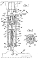
- the mechanism 10 which forms the load-bearing column of furniture components, is made up of an outer tubular component 12 which encloses a coherent coaxial tubular body 14, thereby forming a double structure.
- a piston 32 which runs in the tubular body 14, divides the space into two chambers, 16 and 18.
- the pressurised gas is contained in these chambers and is transferred from one to the other as necessary by the action of valve components which are described on the following pages.
- the outer tubular component 12 has an aperture 20 from which a lever 22 extends. This lever is screwed onto a hinge 24 which is kinematically connected to a moving body 26, part of which has a reduced diameter. The axial movements of this component open and close the circuit.
- the moving piston 32 which defines and separates the two chambers 16 and 18 can be defined as being an "entrainer". It forms a solid body with a rod 34 which contains the passage 30 running through to chamber 16.
- the free end 36 of the above rod 34 has a shaped appendix attached to it. This is locked into a base, indicated as a whole as 38 and indicated in the figure as a broken line, which allows the seat or equivalent piece of furniture to rest firmly on the ground.
- the upper part 40 of the outer tubular component 12 is attached, in the normal way, to the seat 41, which again is indicated by a broken line.
- the structural characteristics of this seat are not described as they are not pertinent to the subject of this invention.
- the lower part of the inner tubular component 34 corresponding to the base 38 is fitted with a step 42.
- the support washer 44 of a flange 46 is kept pressed against this step 42.
- the flange 46 contains the above-mentioned rod 34 by means of a seal 48.
- Another outer seal 50 guarantees the sealing between flange 46 and the shaped end 52 of the inner tubular component 14 mentioned above.
- a valve component 68 is pressure sealed into the upper part of inner tubular component 14, corresponding to the seat 42.
- a hollow space 68' is left between the valve component 68 and the internal walls of tubular component 14 for passage of the gas.
- valve component 68 The hermetic sealing between the upper part of the inner tubular body 14 and the valve component 68 is completed by seals 70 and 72.
- the rod 34 and the piston 32 are pierced along their entire length.
- a pierced pipe 62 preferably made of copper, is inserted into this aperture.
- the upper end of this pipe 62 is attached to a small chamber 66 by means of a pipe-holder 64.
- the passage pierced inside pipe 62 exits into the little chamber 66.
- a hollow space 34' is left between pipe 62 and the inner wall of the aperture in rod 34 to allow passage of the gas.
- Chamber 66 can be made to connect with chamber 18 by means of tubes 28, 28' and hollow space 68', by lowering moving body 26.
- Seals 54 and 56 which are screwed to dorm a kind of stuffing box, by screws 58 and 60 respectively, enclose pipe 62 in correspondence to piston 32 and valve component 68, guaranteeing sealing.
- the way in which the improved mechanism covered by this invention works can be briefly summed up as follows. With the weight of the person seated weighing on the seat 41, let us suppose that the height of the seat has to be adjusted to make the seat lower.
- lever 22 is moved in the direction opposite to that shown by arrow A, thus halting the movement of the gas.
- the pressurised gas moves in the opposite direction, i.e. from chamber 16 to chamber 18, thereby completing the operation of positioning the seat 41 at the height desired by the user.
Landscapes
- Fluid-Damping Devices (AREA)
- Chairs Characterized By Structure (AREA)
- Furniture Connections (AREA)
- Special Chairs (AREA)
- Injection Moulding Of Plastics Or The Like (AREA)
- Hinges (AREA)
- Legs For Furniture In General (AREA)
- Body Structure For Vehicles (AREA)
Claims (3)
Priority Applications (1)
| Application Number | Priority Date | Filing Date | Title |
|---|---|---|---|
| AT85108341T ATE48517T1 (de) | 1984-07-23 | 1985-07-05 | Mechanismus zur vertikalen verstellung von tragenden moebelteilen. |
Applications Claiming Priority (2)
| Application Number | Priority Date | Filing Date | Title |
|---|---|---|---|
| IT2266284U | 1984-07-23 | ||
| ITMI1984U22662U IT8422662U1 (it) | 1984-07-23 | 1984-07-23 | Dispositivo migliorato per il posizionamento selettivo, in altezza di componenti di arredo, quali sedili, poltroncine e/o poltrone. |
Publications (3)
| Publication Number | Publication Date |
|---|---|
| EP0169418A2 EP0169418A2 (de) | 1986-01-29 |
| EP0169418A3 EP0169418A3 (en) | 1986-11-26 |
| EP0169418B1 true EP0169418B1 (de) | 1989-12-13 |
Family
ID=11198998
Family Applications (1)
| Application Number | Title | Priority Date | Filing Date |
|---|---|---|---|
| EP85108341A Expired EP0169418B1 (de) | 1984-07-23 | 1985-07-05 | Mechanismus zur vertikalen Verstellung von tragenden Möbelteilen |
Country Status (5)
| Country | Link |
|---|---|
| EP (1) | EP0169418B1 (de) |
| AT (1) | ATE48517T1 (de) |
| DE (1) | DE3574672D1 (de) |
| ES (1) | ES288264Y (de) |
| IT (1) | IT8422662U1 (de) |
Families Citing this family (3)
| Publication number | Priority date | Publication date | Assignee | Title |
|---|---|---|---|---|
| GB8420623D0 (en) * | 1984-08-14 | 1984-09-19 | Patrick J C | Adjustable supporting column |
| KR100442536B1 (ko) * | 2001-08-28 | 2004-08-04 | 이종환 | 회전의자의 작동레버 설치구조 |
| ES2356202B1 (es) * | 2008-10-10 | 2012-02-17 | Abain Components, S.L. | Columna de mesa con bloqueo y desbloqueo manual y con mecanismo de elevación. |
Family Cites Families (4)
| Publication number | Priority date | Publication date | Assignee | Title |
|---|---|---|---|---|
| DE1062120B (de) * | 1957-04-30 | 1959-07-23 | Ewald Wiemann Maschf | Doppelseitig beaufschlagbarer, druckmittelbetriebener Rueckzylinder |
| BE779062A (fr) * | 1971-02-10 | 1972-05-30 | Corte & Cosso Soc Acc Sempl | Dispositif oleopneumatique de levage et de mise en position, destine notamment a des sieges |
| DE2225342C3 (de) * | 1972-05-25 | 1978-10-12 | Suspa-Federungstechnik Fritz Bauer & Soehne Ohg, 8503 Altdorf | Längenverstellbare Gasfeder |
| IT1136001B (it) * | 1980-05-15 | 1986-08-27 | Sergio Corti | Dispositivo di supporto e di regolazione in altezza del sedile di sedie o poltrone, del ripiano di tavoli e simili |
-
1984
- 1984-07-23 IT ITMI1984U22662U patent/IT8422662U1/it unknown
-
1985
- 1985-07-05 EP EP85108341A patent/EP0169418B1/de not_active Expired
- 1985-07-05 DE DE8585108341T patent/DE3574672D1/de not_active Expired - Fee Related
- 1985-07-05 AT AT85108341T patent/ATE48517T1/de not_active IP Right Cessation
- 1985-07-22 ES ES1985288264U patent/ES288264Y/es not_active Expired
Also Published As
| Publication number | Publication date |
|---|---|
| EP0169418A3 (en) | 1986-11-26 |
| ES288264Y (es) | 1986-07-01 |
| ES288264U (es) | 1985-12-01 |
| EP0169418A2 (de) | 1986-01-29 |
| IT8422662V0 (it) | 1984-07-23 |
| IT8422662U1 (it) | 1986-01-23 |
| DE3574672D1 (de) | 1990-01-18 |
| ATE48517T1 (de) | 1989-12-15 |
Similar Documents
| Publication | Publication Date | Title |
|---|---|---|
| US2859801A (en) | Geometric controller for chairs | |
| FI894905A0 (fi) | Reglerbar oljepneumatisk konsol speciellt foer kontorstolar foersedda med mittpelare. | |
| US5234187A (en) | Chair height adjustment mechanism | |
| EP0169418B1 (de) | Mechanismus zur vertikalen Verstellung von tragenden Möbelteilen | |
| DE3461591D1 (en) | Supporting device for seating furniture with an adjustably inclinable backrest support and an adjustably inclinable seat | |
| US4139175A (en) | Height-adjustable chair or table pedestal | |
| GB1526856A (en) | Lockable supporting spring unit | |
| US4817898A (en) | Adjusting device, particularly for adjustable chairs | |
| JPH053818A (ja) | 椅 子 | |
| US3089741A (en) | Dental equipment | |
| US4784362A (en) | Hydraulic automatically ascending apparatus with a volume-variable oil tank | |
| US3865341A (en) | Dental stool for dentist and dental assistant | |
| FI80990B (fi) | Regleranordning saerskilt foer stolar vars hoejdlaege och lutning kan regleras. | |
| US6427258B1 (en) | Apparatus and method for extending an object | |
| CA2004002C (en) | Chairs | |
| US3240529A (en) | Hoist | |
| FR2350075A1 (fr) | Systeme monte et baisse hydraulique automatique pour siege | |
| US5294086A (en) | Adjustable oleopneumatic amortized support column, for chairs and armchairs | |
| EP0414717B1 (de) | Lastausgleichsvorrichtung | |
| EP0277700A1 (de) | Hydraulische Tragsäule | |
| CN208807899U (zh) | 液动升降椅的升降系统 | |
| GB1514698A (en) | Support structure especially for supporting a vehicle chair comprising an upright supporting post of telescopic construction | |
| KR102856296B1 (ko) | 높이조절 기능을 가지는 의자 | |
| JPH0414966B2 (de) | ||
| WO1989008417A1 (en) | An arrangement for stepless vertical adjustment of a chair seat |
Legal Events
| Date | Code | Title | Description |
|---|---|---|---|
| PUAI | Public reference made under article 153(3) epc to a published international application that has entered the european phase |
Free format text: ORIGINAL CODE: 0009012 |
|
| AK | Designated contracting states |
Kind code of ref document: A2 Designated state(s): AT BE CH DE FR GB LI LU NL SE |
|
| PUAL | Search report despatched |
Free format text: ORIGINAL CODE: 0009013 |
|
| AK | Designated contracting states |
Kind code of ref document: A3 Designated state(s): AT BE CH DE FR GB LI LU NL SE |
|
| 17P | Request for examination filed |
Effective date: 19870312 |
|
| 17Q | First examination report despatched |
Effective date: 19880526 |
|
| GRAA | (expected) grant |
Free format text: ORIGINAL CODE: 0009210 |
|
| AK | Designated contracting states |
Kind code of ref document: B1 Designated state(s): AT BE CH DE FR GB LI LU NL SE |
|
| REF | Corresponds to: |
Ref document number: 48517 Country of ref document: AT Date of ref document: 19891215 Kind code of ref document: T |
|
| REF | Corresponds to: |
Ref document number: 3574672 Country of ref document: DE Date of ref document: 19900118 |
|
| ET | Fr: translation filed | ||
| PLBE | No opposition filed within time limit |
Free format text: ORIGINAL CODE: 0009261 |
|
| STAA | Information on the status of an ep patent application or granted ep patent |
Free format text: STATUS: NO OPPOSITION FILED WITHIN TIME LIMIT |
|
| 26N | No opposition filed | ||
| PGFP | Annual fee paid to national office [announced via postgrant information from national office to epo] |
Ref country code: GB Payment date: 19910628 Year of fee payment: 7 |
|
| PGFP | Annual fee paid to national office [announced via postgrant information from national office to epo] |
Ref country code: LU Payment date: 19910703 Year of fee payment: 7 |
|
| PGFP | Annual fee paid to national office [announced via postgrant information from national office to epo] |
Ref country code: FR Payment date: 19910704 Year of fee payment: 7 |
|
| PGFP | Annual fee paid to national office [announced via postgrant information from national office to epo] |
Ref country code: CH Payment date: 19910708 Year of fee payment: 7 |
|
| PGFP | Annual fee paid to national office [announced via postgrant information from national office to epo] |
Ref country code: SE Payment date: 19910719 Year of fee payment: 7 |
|
| PGFP | Annual fee paid to national office [announced via postgrant information from national office to epo] |
Ref country code: BE Payment date: 19910725 Year of fee payment: 7 |
|
| PGFP | Annual fee paid to national office [announced via postgrant information from national office to epo] |
Ref country code: DE Payment date: 19910729 Year of fee payment: 7 |
|
| PGFP | Annual fee paid to national office [announced via postgrant information from national office to epo] |
Ref country code: NL Payment date: 19910731 Year of fee payment: 7 Ref country code: AT Payment date: 19910731 Year of fee payment: 7 |
|
| EPTA | Lu: last paid annual fee | ||
| PG25 | Lapsed in a contracting state [announced via postgrant information from national office to epo] |
Ref country code: LU Free format text: LAPSE BECAUSE OF NON-PAYMENT OF DUE FEES Effective date: 19920705 Ref country code: GB Effective date: 19920705 Ref country code: AT Effective date: 19920705 |
|
| PG25 | Lapsed in a contracting state [announced via postgrant information from national office to epo] |
Ref country code: SE Effective date: 19920706 |
|
| PG25 | Lapsed in a contracting state [announced via postgrant information from national office to epo] |
Ref country code: LI Effective date: 19920731 Ref country code: CH Effective date: 19920731 Ref country code: BE Effective date: 19920731 |
|
| BERE | Be: lapsed |
Owner name: SOL. ID S.R.L. Effective date: 19920731 |
|
| PG25 | Lapsed in a contracting state [announced via postgrant information from national office to epo] |
Ref country code: NL Effective date: 19930201 |
|
| GBPC | Gb: european patent ceased through non-payment of renewal fee |
Effective date: 19920705 |
|
| NLV4 | Nl: lapsed or anulled due to non-payment of the annual fee | ||
| PG25 | Lapsed in a contracting state [announced via postgrant information from national office to epo] |
Ref country code: FR Effective date: 19930331 |
|
| REG | Reference to a national code |
Ref country code: CH Ref legal event code: PL |
|
| REG | Reference to a national code |
Ref country code: FR Ref legal event code: ST |
|
| PG25 | Lapsed in a contracting state [announced via postgrant information from national office to epo] |
Ref country code: DE Effective date: 19930602 |
|
| EUG | Se: european patent has lapsed |
Ref document number: 85108341.0 Effective date: 19930204 |