EP0169282B1 - Steuergerät - Google Patents
Steuergerät Download PDFInfo
- Publication number
- EP0169282B1 EP0169282B1 EP84305104A EP84305104A EP0169282B1 EP 0169282 B1 EP0169282 B1 EP 0169282B1 EP 84305104 A EP84305104 A EP 84305104A EP 84305104 A EP84305104 A EP 84305104A EP 0169282 B1 EP0169282 B1 EP 0169282B1
- Authority
- EP
- European Patent Office
- Prior art keywords
- stage
- signal
- counter
- output
- input
- Prior art date
- Legal status (The legal status is an assumption and is not a legal conclusion. Google has not performed a legal analysis and makes no representation as to the accuracy of the status listed.)
- Expired - Lifetime
Links
- 230000001419 dependent effect Effects 0.000 claims description 2
- 230000004044 response Effects 0.000 claims description 2
- 238000000034 method Methods 0.000 abstract description 4
- 238000010586 diagram Methods 0.000 description 2
- 230000000694 effects Effects 0.000 description 2
- 238000010276 construction Methods 0.000 description 1
- 230000003247 decreasing effect Effects 0.000 description 1
- 238000003754 machining Methods 0.000 description 1
Images


Classifications
-
- G—PHYSICS
- G05—CONTROLLING; REGULATING
- G05B—CONTROL OR REGULATING SYSTEMS IN GENERAL; FUNCTIONAL ELEMENTS OF SUCH SYSTEMS; MONITORING OR TESTING ARRANGEMENTS FOR SUCH SYSTEMS OR ELEMENTS
- G05B19/00—Programme-control systems
- G05B19/02—Programme-control systems electric
- G05B19/42—Recording and playback systems, i.e. in which the programme is recorded from a cycle of operations, e.g. the cycle of operations being manually controlled, after which this record is played back on the same machine
-
- G—PHYSICS
- G05—CONTROLLING; REGULATING
- G05B—CONTROL OR REGULATING SYSTEMS IN GENERAL; FUNCTIONAL ELEMENTS OF SUCH SYSTEMS; MONITORING OR TESTING ARRANGEMENTS FOR SUCH SYSTEMS OR ELEMENTS
- G05B19/00—Programme-control systems
- G05B19/02—Programme-control systems electric
- G05B19/04—Programme control other than numerical control, i.e. in sequence controllers or logic controllers
- G05B19/045—Programme control other than numerical control, i.e. in sequence controllers or logic controllers using logic state machines, consisting only of a memory or a programmable logic device containing the logic for the controlled machine and in which the state of its outputs is dependent on the state of its inputs or part of its own output states, e.g. binary decision controllers, finite state controllers
Definitions
- the present invention relates to a control apparatus of the multi-level setting type, for example for the control of machine tools, or possibly robots, or positioning means, where a number of successive dimensions, positions, or states have to be achieved in turn.
- Conventional control apparatus of this type sets and displays its preset values mechanically with the resulting inevitable increase in size, so that only 2 to 3 preset values are practicable.
- One object of the invention is to provide a control apparatus so designed that its preset values are set and stored electrically with the resulting increase in the number of preset values and decrease in the size of the apparatus.
- GB-A-1 237 600 discloses a control apparatus of the general type to which this invention relates. Its flexibility is, however, limited, in that a particular sequence of operations always has to start at the beginning and continue through until the end. In addition, at each step of the process further control of the apparatus is entirely dependent upon the result of a single comparison between the desired and expected values of a parameter at the previous step.
- Overrun can of course be reduced or eliminated if an instruction to decelerate is given in advance of the desired stop position, but this requires the user to enter a separate "start decelerating" position for each desired stop position. Every time a stop position is changed, the corresponding "start decelerating" position also has to be changed.
- a control apparatus of the known type defined in the preamble of claim 1 is characterised by the features set out in the characterising portion of Claim 1.
- a facility for storing a plurality of additional preset values, each applicable to more than one stage of the work to be carried out means that, for example, the device may be programmed to start decelerating at a position a predetermined distance short of each of the desired stop points, this predetermined distance requiring to be entered and saved only once when the control apparatus is being set up.
- the device may be programmed to start decelerating at a position a predetermined distance short of each of the desired stop points, this predetermined distance requiring to be entered and saved only once when the control apparatus is being set up.
- FIGURE 1 is a block diagram showing the overall arrangement of the control apparatus
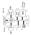
- FIGURE 2 is a block diagram of the control apparatus of FIGURE 1 arranged to simplify understanding of its operation;
- FIGURE 3 is a flow chart showing the operation of the apparatus of FIGURE, 1 and 2.
- the control apparatus includes a counter 11, an input circuit 12; stage computing means 15, preset value input means 18, storage means 13, data transfer means 25, comparison means 21, an output circuit 16, mode selecting means 20, display selective driving means 35 and a display 17 which will be described hereunder.
- the counter 11 is a separate item of hardware which counts a digital input which may represent a position achieved by a work tool for example.
- the input circuit 12 is capable of being supplied with a reset signal, a stepping signal, a start signal, and a stage specifying signal.
- the stage specifying signal enables a selected stage to be specified.
- the stage specifying signal is a signal for specifying the starting stage and is always being input. For example, if the apparatus commences operation from the first stage, a numeral signal corresponding to it shall be input. For another example, if it becomes necessary in the course of operation to bring it back to n-th stage or to skip it to x-th stage after the operation has proceeded foreward or backward successively, a numerical signal corresponding to the n-th or x-th stage shall be input.
- the reset signal is a signal for resetting the output circuit 6 and the stage counter 23 which will be described later.
- the stage counter 23 is reset, it is so arranged that a stage specifying signal is read in.
- the stepping signal is a signal for letting the stage go forward or backward by increasing or decreasing the value of the stage counter 23.
- the starting signal is a signal for instructing the stage set on the stage counter to commence the operation.
- stage specifying signal As the stage specifying signal is always being input as aforesaid, when the apparatus is initially going to start, the reset signal, stepping signal and the starting signal are input in that order. When the apparatus has started the stepping signal and starting signal are input in that order.
- a stage specifying signal corresponding to that specific stage is first input and then a reset signal and a starting signal are input at a proper timing in that order.
- a stage corresponding to said stage is set in the stage counter and the apparatus commences the operation beginning with the specified stage.
- the preset value input means 18 is a means for inputting the preset values corresponding to the various stages of work, and it may for example be a keyboard.
- the values may represent dimensions in a machining operation, or positions in a sequence of movement.
- the storage means 13 stores a large number of the preset values corresponding to the stages of work. It comprises a stage counter 23 and a preset value storage means 33 and it usually includes a RAM.
- the step counter is reset based on a reset signal from the stage computing means, sets a corresponding stage based on a stage specifying signal , and adjusts the count value based on a stepping signal.
- the preset value storage means 33 memorises the preset value signals coming from the preset value input means 18. It memorises singular or plural preset values corresponding to each stage and it gives the relevant present value in accordance with an instruction coming from the stage counter 23.
- the stage computing means 15 is responsive to the signals from the input circuit 12.
- stage computing means sends signals to read the stage counter 23 and output circuit 6.
- the stage computing means 15 checks the status of the stage counter 23 and, if it is not in reset condition, sends a signal to the stage counter 23 to move the count value backwards or forwards. If it is in reset condition, the stage computing means 15 reads a stage specifying signal and sends a signal for setting the stage value corresponding to said stage specifying signal to stage counter 23. If a start checks the status of the stage counter 23 and if it is not in the reset condition sends a signal so that the stage indicated by the stage counter is performed.
- the data transfer means 25 writes the preset signals from the preset value input means 18 in the preset value storage means 33 and it also reads and transfers the preset value corresponding to the current stage of work shown in the stage counter 23 from the preset value storage means 33.
- the comparison means 21 compares the output of the counter 11 and the preset value from the data transfer means 25 as to relative magnitude and equality and generates a signal corresponding to the comparison. It is to be noted that in the operating mode, the comparison means 21 and the data transfer means 25 are each actuated in response to the supply of a start signal.
- the output circuit 16 is responsive to the output of the comparison means 21 to generate a control output.
- the mode selecting means 20 enables the user to select an operating mode or a setting mode.
- the setting mode is for effecting the storage of the number of the stages and their preset values in the storage means 33, and the operating mode is for normal operation to perform those stages.
- the display selective driving means 35 is responsive to the mode signals from the mode selecting means 20 so that the output of the counter 11 is generated in the operating mode and the preset value from the data transfer means 25 is generated in the setting mode.
- the display 17 is responsive to the output from the display selective driving means 35 to display the output of the counter or the preset value and it also displays the number of the running stage. These displays are usually made in the form of digital values.
- stage computing means 15, the data transfer means 25, and the display selective driving means 35 are formed by an ROM with permanently stored programs and a CPU operable in accordance with the programs.
- the comparison means 21 may be provided by the ROM and the CPU mentioned above or alternatively it may comprise a separate comparison computing unit.
- the present invention is not of course limited to this arrangement.
- the control apparatus makes it possible to define a large number of preset values corresponding to the stages of work, while the apparatus can be small.
- the counter 11 is a separate item of computer hardware and is not a part of the ROM and CPU mentioned above, and so is a dedicated item and can count at a high speed.
- numeral 1 designates an up-down counter which counts a digital input. Also in relation to FIGURE 1, the counter 1 incorporates comparators corresponding to the comparison means 21.
- Numeral 2 designates an input circuit which is supplied with input signals including a reset signal, stepping signals, a start signal and a stage specifying signal.
- Numeral 3 designates an RAM storing the preset values corresponding to the stages of work.
- Numeral 4 designates an ROM storing predetermined programs.
- Numeral 5 designates a CPU for performing various computational operations in accordance with the programs in the ROM 4. In relation to FIGURE 1, the CPU 5 includes the stage computing means 15, the data transfer means 25 and the display selective driving means 35.
- Numeral 6 designates an external output in accordance with the comparison result of the comparator in the counter 1 through the CPU 5.
- Numeral 7 designates a display unit for displaying the current stage and the output of the counter 1 or a preset value.
- Numeral 8 designates a keyboard which is used mainly for the purpose of writing the preset values in the RAM 3. In relation to FIGURE 1 the keyboard 8 forms the preset value input means 18.
- Numeral 9 designates a cassette interface which is used to write preset values in the RAM 3 in accordance with an externally reproduced input and to record the preset values of the RAM 3 as a recorded output on an external magnetic tape or the like.
- Numeral 10 designates a mode selector switch which is used for the selection of various modes.
- the control signals to be input into the input circuit 2 are actually input as mentioned hereunder.
- a stage specifying signal is always being input as aforesaid.
- Other signals are input in the order 'a reset signal - a stepping signal - a starting signal... a stepping signal - a starting signal'.
- a stage specifying signal corresponding to that specified stage shall be input beforehand and then a reset signal is input at a proper timing. Then, a stepping signal and a starting signal follow it as described above.
- a stage specifying signal corresponding to said fourth stage shall be input beforehand and, when the current stage is over, a reset signal shall be input.
- the RAM 3 can store a large number of preset values, if the counter apparatus of this embodiment is used as a multipoint positioning apparatus for example, any given supplementary data for positioning control purposes can also be stored in the ram 3.
- the keyboard 8 may be used to input additional present values (X,Y), which are written to the RAM 3.
- the CPU calculates (I c - X) and (I c -Y), thus providing three values to be compared with the output of the counter (11) for the current stage (c) instead of one. In this way it is possible to deliver to external units the control signals corresponding to the preset values and effect a finer and proper positioning control.
- control apparatus of this embodiment is used as a multipoint positioning counter, it is conceivable to provide means for selecting such modes as stop, adjusting, setting, copying, and cassette modes in addition to the above-mentioned operating mode.
- the stop mode stops the operation of the apparatus as a whole and the adjusting mode changes the preset values in the RAM 3, that is, during the continued operation alternative data are written in the RAM 3 by the keyboard 8.
- the setting mode writes the preset values in the RAM 3.
- the copying mode writes the current output of the counter 1 in the RAM 3 in accordance with the actual work
- the cassette mode effects the ensuring operations through the cassette interface 9.
- the same preset values are written in the RAM of each machine and thus, after the data have been recorded on a magnetic tape, the data are written in the RAM 3 through the cassette interface 9. Also, the contents of the RAM of one machine can be written into the RAM of the other machine through the cassette interface 9.
Landscapes
- Physics & Mathematics (AREA)
- General Physics & Mathematics (AREA)
- Engineering & Computer Science (AREA)
- Automation & Control Theory (AREA)
- Numerical Control (AREA)
- Control Of Position Or Direction (AREA)
- Apparatus For Radiation Diagnosis (AREA)
- Vehicle Body Suspensions (AREA)
- Transplanting Machines (AREA)
- Feedback Control In General (AREA)
Claims (8)
- Steuervorrichtung zum Steuern eines Arbeitsvorganges, wobei die Vorrichtung selektiv zumindest zwischen einer Einstell-Betriebsart und einer Arbeits-Betriebsart mit Hilfe einer Betriebsart-Wähleinrichtung (20) schaltbar ist; mit einer Voreinstellwert-Eingabeeinrichtung (18), um in der Einstell-Betriebsart eine Mehrzahl von Voreinstellwerten (Ii) einzugeben, die je einer Stufe (i) der auszuführenden Arbeit entsprechen, und einer Speichereinrichtung (13) zum elektrischen Speichern der Voreinstellwerte (Ii), einem Zähler (11) zum Zählen eines sich auf den Arbeitsvorgang beziehenden digitalen Eingangs in der Arbeits-Betriebsart; einer Vergleichseinrichtung (21), die in Ansprechen auf ein einem Eingangskreis (12) zugeführtes Startsignal betreibbar ist, um einen Ausgang des Zählers (11) und den gespeicherten Voreinstellwert (Ic) entsprechend der erreichten Arbeitsstufe (c) zu vergleichen und ein das Vergleichsergebnis anzeigendes Ausgangssignal zu erzeugen; einem auf das Ausgangssignal ansprechenden Ausgangskreis (16) zum Erzeugen eines Steuerausgangs; und einer Stufenberechnungseinrichtung (15), die auf ein dem Eingangskreis (12) zugeführtes Schrittsignal anspricht, um den Arbeitsvorgang schrittweise zur nächsten (C+1) oder vorhergehenden (C-1) Stufe umzuschalten, und die auf ein selektiv dem Eingangskreis (12) zugeführtes Rückstellsignal anspricht, um den Arbeitsvorgang auf eine ausgewählte Arbeitsstufe zurückzustellen, dadurch gekennzeichnet, daß in der Einstell-Betriebsart die Voreinstellwert-Eingabeeinrichtung (18) eingerichtet ist, einen zusätzlichen Voreinstellwert (X), der für mehr als eine Stufe der durchzuführenden Arbeit anwendbar ist, einzugeben und die Speichereinrichtung (13) eingerichtet ist, diesen zusätzlichen Voreinstellwert (X) zu speichern; und daß in der Arbeits-Betriebsart die Vergleichseinrichtung (21) eingerichtet ist, den Ausgang des Zählers (11) mit einem zusätzlichen Wert (Ic-X), der abhängig ist vom gespeicherten Voreinstellwert (Ic) für die momentane Stufe (c) und vom vorliegenden zusätzlichen Wert (X), zu vergleichen, um eine zusätzliches Ausgangssignal zu erzeugen, welches an den Ausgangskreis (16) angelegt wird, um einen zusätzlichen Steuerausgang zu erzeugen.
- Steuervorrichtung nach Anspruch 1, bei der die Stufenberechnungseinrichtung (15) eingerichtet ist, ein Momentanstufensignal zu erzeugen.
- Steuervorrichtung nach Anspruch 1 oder 2, bei der die Vergleichseinrichtung (21) eingerichtet ist, den Ausgang des Zählers (11) mit dem entsprechenden Voreinstellwert hinsichtlich der relativen Größe und Gleichheit zu vergleichen.
- Steuervorrichtung nach einem der vorhergehenden Ansprüche, weiters mit einer Anzeige-selektiven Treibereinrichtung, die auf die Betriebsart-Wähleinrichtung (20) anspricht, um ein Signal entsprechend dem Zählerausgang oder dem Voreinstellwert für die momentane Stufe zu erzeugen.
- Steuervorrichtung nach Anspruch 4, weiters mit einer Anzeigeeinrichtung (17), die auf das Signal aus der Anzeigeselektiven Treibereinrichtung (35) anspricht, um den Zählerausgang oder den Voreinstellwert der momentanen Stufe und die momentane Stufe anzuzeigen.
- Steuervorrichtung nach einem der vorhergehenden Ansprüche, bei der der Zähler (11) von allen anderen Bauteilen der Vorrichtung getrennt ist.
- Steuervorrichtung nach einem der vorhergehenden Ansprüche, zur Verwendung bei der Steuerung einer aufeinanderfolgenden Reihe von Arbeitsgängen, die von einer Maschine ausgeführt werden.
- Steuervorrichtung nach einem der vorhergehenden Ansprüche, eingerichtet zum neuerlichen Starten des Betriebs von der ausgewählten Stufe an auf den Empfang eines eine Stufe angebenden Signals, gefolgt vom Rückstellsignal, durch den Eingabekreis (12).
Priority Applications (3)
| Application Number | Priority Date | Filing Date | Title |
|---|---|---|---|
| EP84305104A EP0169282B1 (de) | 1984-07-26 | 1984-07-26 | Steuergerät |
| AT84305104T ATE62080T1 (de) | 1984-07-26 | 1984-07-26 | Steuergeraet. |
| DE8484305104T DE3484349D1 (de) | 1984-07-26 | 1984-07-26 | Steuergeraet. |
Applications Claiming Priority (1)
| Application Number | Priority Date | Filing Date | Title |
|---|---|---|---|
| EP84305104A EP0169282B1 (de) | 1984-07-26 | 1984-07-26 | Steuergerät |
Publications (2)
| Publication Number | Publication Date |
|---|---|
| EP0169282A1 EP0169282A1 (de) | 1986-01-29 |
| EP0169282B1 true EP0169282B1 (de) | 1991-03-27 |
Family
ID=8192703
Family Applications (1)
| Application Number | Title | Priority Date | Filing Date |
|---|---|---|---|
| EP84305104A Expired - Lifetime EP0169282B1 (de) | 1984-07-26 | 1984-07-26 | Steuergerät |
Country Status (3)
| Country | Link |
|---|---|
| EP (1) | EP0169282B1 (de) |
| AT (1) | ATE62080T1 (de) |
| DE (1) | DE3484349D1 (de) |
Citations (1)
| Publication number | Priority date | Publication date | Assignee | Title |
|---|---|---|---|---|
| GB1237600A (en) * | 1968-02-22 | 1971-06-30 | Siemens Ag | Storage arrangements for injection moulding machines |
Family Cites Families (1)
| Publication number | Priority date | Publication date | Assignee | Title |
|---|---|---|---|---|
| US3689892A (en) * | 1970-03-18 | 1972-09-05 | Electroglas Inc | Electronic control apparatus having learn and automatic operate modes |
-
1984
- 1984-07-26 EP EP84305104A patent/EP0169282B1/de not_active Expired - Lifetime
- 1984-07-26 AT AT84305104T patent/ATE62080T1/de not_active IP Right Cessation
- 1984-07-26 DE DE8484305104T patent/DE3484349D1/de not_active Expired - Fee Related
Patent Citations (1)
| Publication number | Priority date | Publication date | Assignee | Title |
|---|---|---|---|---|
| GB1237600A (en) * | 1968-02-22 | 1971-06-30 | Siemens Ag | Storage arrangements for injection moulding machines |
Also Published As
| Publication number | Publication date |
|---|---|
| EP0169282A1 (de) | 1986-01-29 |
| ATE62080T1 (de) | 1991-04-15 |
| DE3484349D1 (de) | 1991-05-02 |
Similar Documents
| Publication | Publication Date | Title |
|---|---|---|
| US6885909B2 (en) | Numerical controller | |
| EP0172486A2 (de) | Spurfolgendes Robotergerät | |
| US5315503A (en) | Numerical control apparatus having a teaching function and a method of teaching a machining program thereby | |
| US4649252A (en) | Wire-cut electric discharge machining method | |
| US4700313A (en) | Plural turret system with display of permitted and non-permitted simultaneous machining operations | |
| EP0046343A2 (de) | Verfahren und Gerät zur numerischen Steuerung | |
| EP0127122B1 (de) | Numerisches Steuersystem mit einer Anzeige-Einheit und vom System gesteuerte Werkzeugmaschine | |
| US4661912A (en) | Numerical control device for scheduling machining of groups of workpieces | |
| US5298843A (en) | Method for restarting punch press machine and numerical controller | |
| US4150427A (en) | Machine tool data system and method | |
| US4059746A (en) | Pulse distribution apparatus for linear interpolation in a numerical control system | |
| EP0169282B1 (de) | Steuergerät | |
| CA1215763A (en) | Electronic sewing machine with a pattern display | |
| WO1994017459A1 (en) | Method of execution of nc machining program | |
| US4056850A (en) | Absolute relative position encoder processor and display | |
| US3895354A (en) | Program editor for machine control | |
| US4164693A (en) | Method and system for producing linear contouring movement | |
| US5473535A (en) | Method and apparatus for preparing pattern data for machine tool | |
| US3824550A (en) | Read-only-memory storage apparatus for controlling data logging apparatus | |
| EP0099733A2 (de) | Verfahren und Einrichtung zur Herstellung von NS-Programmen | |
| JP4310018B2 (ja) | Nc工作機械における工具の位置補正方法 | |
| US3609323A (en) | Interpolating servomechanism control system with operations carried out in binary coded decimal format due to a {37 plus-six{38 {0 correction factor | |
| JPH10301614A (ja) | 数値制御装置 | |
| US5270940A (en) | Contour configuration machining method | |
| EP0935179A1 (de) | Numerische steuerung mit lehr-/wiedergabefunktion |
Legal Events
| Date | Code | Title | Description |
|---|---|---|---|
| PUAI | Public reference made under article 153(3) epc to a published international application that has entered the european phase |
Free format text: ORIGINAL CODE: 0009012 |
|
| AK | Designated contracting states |
Designated state(s): AT BE CH DE FR GB IT LI LU NL SE |
|
| 17P | Request for examination filed |
Effective date: 19860718 |
|
| 17Q | First examination report despatched |
Effective date: 19880620 |
|
| ITF | It: translation for a ep patent filed | ||
| GRAA | (expected) grant |
Free format text: ORIGINAL CODE: 0009210 |
|
| AK | Designated contracting states |
Kind code of ref document: B1 Designated state(s): AT BE CH DE FR GB IT LI LU NL SE |
|
| PG25 | Lapsed in a contracting state [announced via postgrant information from national office to epo] |
Ref country code: SE Effective date: 19910327 |
|
| REF | Corresponds to: |
Ref document number: 62080 Country of ref document: AT Date of ref document: 19910415 Kind code of ref document: T |
|
| REF | Corresponds to: |
Ref document number: 3484349 Country of ref document: DE Date of ref document: 19910502 |
|
| PGFP | Annual fee paid to national office [announced via postgrant information from national office to epo] |
Ref country code: LU Payment date: 19910508 Year of fee payment: 8 |
|
| ET | Fr: translation filed | ||
| PGFP | Annual fee paid to national office [announced via postgrant information from national office to epo] |
Ref country code: BE Payment date: 19910613 Year of fee payment: 8 |
|
| PGFP | Annual fee paid to national office [announced via postgrant information from national office to epo] |
Ref country code: AT Payment date: 19910730 Year of fee payment: 8 |
|
| PGFP | Annual fee paid to national office [announced via postgrant information from national office to epo] |
Ref country code: NL Payment date: 19910731 Year of fee payment: 8 Ref country code: CH Payment date: 19910731 Year of fee payment: 8 |
|
| EPTA | Lu: last paid annual fee | ||
| PLBE | No opposition filed within time limit |
Free format text: ORIGINAL CODE: 0009261 |
|
| STAA | Information on the status of an ep patent application or granted ep patent |
Free format text: STATUS: NO OPPOSITION FILED WITHIN TIME LIMIT |
|
| 26N | No opposition filed | ||
| PG25 | Lapsed in a contracting state [announced via postgrant information from national office to epo] |
Ref country code: LU Free format text: LAPSE BECAUSE OF NON-PAYMENT OF DUE FEES Effective date: 19920726 Ref country code: AT Effective date: 19920726 |
|
| PG25 | Lapsed in a contracting state [announced via postgrant information from national office to epo] |
Ref country code: LI Effective date: 19920731 Ref country code: CH Effective date: 19920731 Ref country code: BE Effective date: 19920731 |
|
| BERE | Be: lapsed |
Owner name: KOYO DENSHI KOGYO K.K. (KOYO ELECTRONICS INDUSTRI Effective date: 19920731 |
|
| PG25 | Lapsed in a contracting state [announced via postgrant information from national office to epo] |
Ref country code: NL Effective date: 19930201 |
|
| NLV4 | Nl: lapsed or anulled due to non-payment of the annual fee | ||
| REG | Reference to a national code |
Ref country code: CH Ref legal event code: PL |
|
| PGFP | Annual fee paid to national office [announced via postgrant information from national office to epo] |
Ref country code: FR Payment date: 19940627 Year of fee payment: 11 |
|
| PGFP | Annual fee paid to national office [announced via postgrant information from national office to epo] |
Ref country code: GB Payment date: 19940718 Year of fee payment: 11 |
|
| PGFP | Annual fee paid to national office [announced via postgrant information from national office to epo] |
Ref country code: DE Payment date: 19940819 Year of fee payment: 11 |
|
| PG25 | Lapsed in a contracting state [announced via postgrant information from national office to epo] |
Ref country code: GB Effective date: 19950726 |
|
| GBPC | Gb: european patent ceased through non-payment of renewal fee |
Effective date: 19950726 |
|
| PG25 | Lapsed in a contracting state [announced via postgrant information from national office to epo] |
Ref country code: DE Effective date: 19960402 |
|
| PG25 | Lapsed in a contracting state [announced via postgrant information from national office to epo] |
Ref country code: FR Effective date: 19960430 |
|
| REG | Reference to a national code |
Ref country code: FR Ref legal event code: ST |
|
| REG | Reference to a national code |
Ref country code: FR Ref legal event code: ST |
|
| REG | Reference to a national code |
Ref country code: FR Ref legal event code: ST |