EP0169065B1 - Model flying vehicle with smooth landing - Google Patents
Model flying vehicle with smooth landing Download PDFInfo
- Publication number
- EP0169065B1 EP0169065B1 EP85305104A EP85305104A EP0169065B1 EP 0169065 B1 EP0169065 B1 EP 0169065B1 EP 85305104 A EP85305104 A EP 85305104A EP 85305104 A EP85305104 A EP 85305104A EP 0169065 B1 EP0169065 B1 EP 0169065B1
- Authority
- EP
- European Patent Office
- Prior art keywords
- spindle portion
- wing means
- cap member
- wing
- flying body
- Prior art date
- Legal status (The legal status is an assumption and is not a legal conclusion. Google has not performed a legal analysis and makes no representation as to the accuracy of the status listed.)
- Expired - Lifetime
Links
- 238000010137 moulding (plastic) Methods 0.000 claims description 3
- 125000006850 spacer group Chemical group 0.000 claims description 3
- 230000003028 elevating effect Effects 0.000 claims description 2
- 230000005484 gravity Effects 0.000 description 2
- 230000001174 ascending effect Effects 0.000 description 1
- 238000000465 moulding Methods 0.000 description 1
- 230000006641 stabilisation Effects 0.000 description 1
- 238000011105 stabilization Methods 0.000 description 1
Images


Classifications
-
- A—HUMAN NECESSITIES
- A63—SPORTS; GAMES; AMUSEMENTS
- A63H—TOYS, e.g. TOPS, DOLLS, HOOPS OR BUILDING BLOCKS
- A63H27/00—Toy aircraft; Other flying toys
- A63H27/12—Helicopters ; Flying tops
Definitions
- This invention relates to a model flying vehicle, and more particularly to a model flying vehicle with a configuration for stabilization of the vehicle during landing.
- Model flying vehicles especially helicopter toys are given a sufficient force of lift to take off through a source of power such as a twisted rubber coil.
- a source of power such as a twisted rubber coil.
- the conventional vehicle descends while the elevation angle of the main wings remains the same as that during take-off, and the vehicle will therefore land in an unstable state (that is, at an angle with respect to the ground) and in some cases the flying body will whirl several times prior to landing. It is, therefore, highly likely that the flying body will be subject to a large impact during landing and that the flying body, the main wings or the tail wings will be damaged.
- US-A-2 931 132 discloses a model flying vehicle in which the angle of elevation of the wings varies according to the action of centrifugal forces due to their speed of rotation.
- the model vehicle disclosed relies on the rotor being freely rotatable after the vehicle has been given an initial upward thrust, and does not include a built-in power source.
- a model flying vehicle structure comprising: a flying body; a spindle portion rotatably mounted on said flying body; wing means secured to said spindle portion for rotation therewith, said wing means comprising two blade portions; a shaft extending through said spindle portion; an axially movable cap member on said shaft arranged to be selectively engageable with said spindle portion; spring means disposed between said spindle portion and said cap member for normally biasing said cap member out of engagement with said spindle portion; an elastic member operatively connected to said flying body and said shaft for engaging said cap member with said spindle portion to provide a force of rotation to said spindle portion and said wing means for elevating said flying body by lift produced by said rotating wing means; and projections disposed on one side of each blade portion for selective engagement with said cap member; wherein manually rotating said wing means relative to said flying body twists said elastic member to provide stored energy for rotating said spindle portion and said wing means and displaces said cap member into engagement with
- the elevation angle of the wing means may be reduced into a zero (a flat state), permitting the flying body to descend naturally only due to its gravity and with a high degree of stability as if it floats in the sky. This avoids the objectionable situation where the flying body bumps against the ground with a large impact and the flying body or the wing means become damaged or battered.
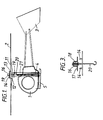
- Fig. 1 is a side view of a flying vehicle according to the present invention
- Fig. 2 is an exploded perspective of the flying vehicle shown in Fig. 1
- Fig. 3 is a cross sectional view of a shaft assembly in the flying vehicle of Figs. 1 and 2.
- Figs. 4(a) to 4(d) show how to assemble a main wing in the flying vehicle as shown in Figs. 1 and 2.
- Figs. 1 and 2 there are illustrated a side view and exploded perspective view of a flying vehicle, a helicopter toy, according to an embodiment of the present invention.
- the flying vehicle generally comprises a flying body 1, a main wing 2, a tail wing 3, a power source 4 such as twisted rubber and a leg 5.
- the majority of the flying vehicle, except for a few components, is made of a plastic molding and designed in shape and weight so that it may easily be given the force of lift.
- the main wing 2 has a pair of blades 11, 11 each having a projection 13, 13 in the vicinity of the periphery of a spindle portion 12.
- the main wing 2 is made of plastic molding as described above, which molding is so flexible that its elevation angle is easily variable.
- the spindle portion 12 of the main wing 2 is molded separately from the blade portions 11, 11 and shaped into a cylinder with a pair of engaging pawls 14, 14 at its top. Then, the blade portions 11, 11 and the spindle portion 12 are jointed into a single unit through the use of joints 15, 15.
- Disposed over the main wing 2 is a cap member 16 which has on its base a pair of openings 17, 17 for receiving the engaging pawls 14, 14 therein.
- the stem portion of the cap member 16 is also adapted to receive a spring 18 therein.
- the rubber coil of the power source 4 is secured in the following manner. While the spring 18 is inserted into the stem portion of the cap member 16 and a pair of spacers 19, 19 are secured above and below the spindle portion 12 of the main wing 2, a shaft 20 is positioned to pass through the center of the spindle portion 12 and the cap member 16 with its upper end engaging into the cap member 16 and a hook at its lower end extending into a stud 21 at the center of the flying body 1. The rubber coil is wound between the hooked lower end of the shaft 20 and the leg 5.
- Fig. 3 depicts in more detail the shaft 20 secured in the above manner.
- the operator places the engaging pawls 14, 14 into alignment with the openings 17, 17 in the cap member 16 and winds up the rubber coil by rotating the main wing 2 while holding the body 1.
- the main wing 2 is forced down together with the cap member 16 by the force of the twisted rubber coil against the spring 18. Because of the projections on the cap member 16 being in contact with the counterparts 13, 13 on the main wing 1, the periphery of the projections on the blade portions are pushed down to provide the main wing with a given elevation angle.
- the flying body 1 is given thrust by the rubber coil 4 and lift by the elevation angle of the main wing, thus starting take-off.
- the pawls 14, 14 of the spindle portion 12 are kept in engagement with the openings 17, 17 in the cap member 16 so that the flying body 2 can keep ascending due to the proper elevation angle of the main wing 2.
- the flying body 1 loses the thrust and starts descending. Under these circumstances, the rubber coil has no pulling power so that the spring 18 acts to lift the cap member 16 and disengage the pawls 14, 14 of the spindle portion 12 from the openings 17, 17 in the cap member 17. Upon such disengagement, there is nothing that pushes down the projections 13, 13, so that the blade portions 11, 11 of the main wing resume a flat state due to its flexibility. The result is that the whole of the flying vehicle descends naturally only due to its gravity while keeping a stable flying position in the sky. There is no likelihood of the flying body losing balance or abruptly whirling during landing. The impact on the flying body during landing is reduced to a minimum, whereby damage to the vehicle is prevented.
- Figs. 4(a) to 4(d) illustrates how to assemble the main wing 2.
- the main wing 2 comprises the spindle portion 12 and the blade portions 11 both molded separately from each other.
- the spindle portion 12 further has an insert 27 with a stop 22 at a higher level and a stay 23 with a pair of openings 24, 24 at a lower level.
- the blade portion 11, on the other hand, further includes a curved groove 25 and a pair of projections 26, 26 which are to be received within the respective openings 24, 24 in the stay 23.
- the blade portion 11 is placed topside down, with the curved groove receiving the insert 27 of the spindle portion 12.
- the stop 22 extends out of the groove 25 so that the blade portion 11 is prevented from separating from the spindle portion 12. Then, the blade portion 11 is turned by 180 degrees as indicated in Fig. 4(b) so as to place the projections 26, 26 into alignment with the openings 24, 24. Finally, the tip of the stay 23 (that is, the openings) are tightly secured into the projections 26, 26. It is important to note that the stay 23 itself is flexible and forces the blade portion 11 to a flat position when the power source is disenabled or when the pawls 14, 14 of the spindle portion 12 are disengaged from the openings 17, 17 in the cap member 17. Another important function of the stay 23 is to keep the blade portion 11 from erecting in a vertical direction.
- the main wing returns from the slanting position (that is, with a proper elevation angle) to the flat position when the power is disengaged, thereby ensuring stable and smooth landing without impact or damage to the flying body or the wing.
Landscapes
- Toys (AREA)
- Transition And Organic Metals Composition Catalysts For Addition Polymerization (AREA)
- Holo Graphy (AREA)
- Molds, Cores, And Manufacturing Methods Thereof (AREA)
Priority Applications (1)
| Application Number | Priority Date | Filing Date | Title |
|---|---|---|---|
| AT85305104T ATE62826T1 (de) | 1984-07-17 | 1985-07-17 | Modellflugzeug fuer weiche landung. |
Applications Claiming Priority (2)
| Application Number | Priority Date | Filing Date | Title |
|---|---|---|---|
| JP148278/84 | 1984-07-17 | ||
| JP14827884A JPS6129381A (ja) | 1984-07-17 | 1984-07-17 | 模型飛行体 |
Publications (3)
| Publication Number | Publication Date |
|---|---|
| EP0169065A2 EP0169065A2 (en) | 1986-01-22 |
| EP0169065A3 EP0169065A3 (en) | 1987-06-10 |
| EP0169065B1 true EP0169065B1 (en) | 1991-04-24 |
Family
ID=15449185
Family Applications (1)
| Application Number | Title | Priority Date | Filing Date |
|---|---|---|---|
| EP85305104A Expired - Lifetime EP0169065B1 (en) | 1984-07-17 | 1985-07-17 | Model flying vehicle with smooth landing |
Country Status (5)
| Country | Link |
|---|---|
| US (1) | US4674986A (enExample) |
| EP (1) | EP0169065B1 (enExample) |
| JP (1) | JPS6129381A (enExample) |
| AT (1) | ATE62826T1 (enExample) |
| DE (1) | DE3582619D1 (enExample) |
Families Citing this family (4)
| Publication number | Priority date | Publication date | Assignee | Title |
|---|---|---|---|---|
| JP2646267B2 (ja) * | 1989-06-06 | 1997-08-27 | 有限会社ワイルドギヤー | ヘリコプター玩具 |
| US5304090A (en) * | 1993-01-19 | 1994-04-19 | Vanni Robert R | Toy helicopter having forwardly inclined rotor shaft |
| CN102743883B (zh) * | 2012-07-13 | 2014-12-10 | 罗之洪 | 一种航模直升机 |
| US9352241B1 (en) | 2015-01-07 | 2016-05-31 | James C Gast | Rubber band powered toy vehicle |
Family Cites Families (13)
| Publication number | Priority date | Publication date | Assignee | Title |
|---|---|---|---|---|
| CA716768A (en) * | 1965-08-31 | K. Bross Helmut | Toy | |
| US1669758A (en) * | 1925-04-07 | 1928-05-15 | Isacco | Helicopter |
| US2308916A (en) * | 1940-09-26 | 1943-01-19 | Halligan John Francis | Vertically rising flying device |
| US2389170A (en) * | 1941-10-18 | 1945-11-20 | Edward A Stalker | Rotary wing aircraft |
| US2537393A (en) * | 1946-07-27 | 1951-01-09 | Paul E Bisch | Toy helicopter |
| DE875468C (de) * | 1950-01-02 | 1953-05-04 | Jacob Berg K G Blechwarenfabri | Hubschrauber als Spielzeug oder Lehrmittel |
| DE884771C (de) * | 1950-01-02 | 1953-07-30 | Jacob Berg K G Blechwarenfabri | Hubschrauber als Spielzeug oder Lehrmittel |
| GB751828A (en) * | 1953-11-30 | 1956-07-04 | Adam Krautkramer I | Toy helicopter |
| DE1692292U (de) * | 1954-11-13 | 1955-01-27 | Bernhard Eickenbrock | Flugrotor mit automatischer fluegelumstellung, geeignet als tragwerk fuer spielzeughubschrauber. |
| US2931132A (en) * | 1955-02-25 | 1960-04-05 | Griessl Rudolf | Toy helicopter |
| US3108641A (en) * | 1961-03-16 | 1963-10-29 | Taylor Dana Lee | Helicopter control system |
| US3194521A (en) * | 1962-10-19 | 1965-07-13 | George H Rider | Kite |
| FR2269986A1 (en) * | 1974-05-07 | 1975-12-05 | Nitti Italo | Model helicopter powered by miniature combustion engine - has cable operated linkage controlling lift blade angles of incidence |
-
1984
- 1984-07-17 JP JP14827884A patent/JPS6129381A/ja active Granted
-
1985
- 1985-07-17 US US06/756,072 patent/US4674986A/en not_active Expired - Fee Related
- 1985-07-17 DE DE8585305104T patent/DE3582619D1/de not_active Expired - Lifetime
- 1985-07-17 AT AT85305104T patent/ATE62826T1/de not_active IP Right Cessation
- 1985-07-17 EP EP85305104A patent/EP0169065B1/en not_active Expired - Lifetime
Also Published As
| Publication number | Publication date |
|---|---|
| ATE62826T1 (de) | 1991-05-15 |
| EP0169065A3 (en) | 1987-06-10 |
| DE3582619D1 (de) | 1991-05-29 |
| US4674986A (en) | 1987-06-23 |
| JPS6129381A (ja) | 1986-02-10 |
| JPH0421512B2 (enExample) | 1992-04-10 |
| EP0169065A2 (en) | 1986-01-22 |
Similar Documents
| Publication | Publication Date | Title |
|---|---|---|
| US6769949B2 (en) | Power-driven ornithopter | |
| US5163861A (en) | Wing-operated flying toy, and a process for automatically locking the wings, at the end of a flight | |
| US3955817A (en) | Toy boomerang | |
| US20100120321A1 (en) | Vertical take off plane | |
| US4084345A (en) | Toy helicopter | |
| US3082572A (en) | Aerial toy | |
| US5173069A (en) | Autorotative flyer | |
| JP2646267B2 (ja) | ヘリコプター玩具 | |
| US5259802A (en) | Component frisbee | |
| US3273834A (en) | Air drop autorotating gyroplane drop chutes | |
| US4335537A (en) | Toy aircraft | |
| CN115140302B (zh) | 一种共轴无人机的飞控系统 | |
| EP0169065B1 (en) | Model flying vehicle with smooth landing | |
| US7971824B2 (en) | Flying object | |
| US3108641A (en) | Helicopter control system | |
| US4030238A (en) | Rotating toys, particularly flying toys | |
| US2035531A (en) | Toy aeroplane | |
| JPS5950559B2 (ja) | ヘリコプタ主回転翼の羽ばたき運動制限装置 | |
| KR100498743B1 (ko) | 전동식 모형비행기 | |
| US3479764A (en) | Aerial toy | |
| US3654729A (en) | Model airplane | |
| US4805853A (en) | Automatic action toy glider-kite string flyer | |
| US2845746A (en) | Toy flying machine | |
| US3930332A (en) | Airfoil rotor for a toy helicopter | |
| US4655719A (en) | Delayed-release suspension device |
Legal Events
| Date | Code | Title | Description |
|---|---|---|---|
| PUAI | Public reference made under article 153(3) epc to a published international application that has entered the european phase |
Free format text: ORIGINAL CODE: 0009012 |
|
| AK | Designated contracting states |
Designated state(s): AT BE CH DE FR GB IT LI LU NL SE |
|
| PUAL | Search report despatched |
Free format text: ORIGINAL CODE: 0009013 |
|
| AK | Designated contracting states |
Kind code of ref document: A3 Designated state(s): AT BE CH DE FR GB IT LI LU NL SE |
|
| 17P | Request for examination filed |
Effective date: 19871209 |
|
| 17Q | First examination report despatched |
Effective date: 19881014 |
|
| GRAA | (expected) grant |
Free format text: ORIGINAL CODE: 0009210 |
|
| AK | Designated contracting states |
Kind code of ref document: B1 Designated state(s): AT BE CH DE FR GB IT LI LU NL SE |
|
| PG25 | Lapsed in a contracting state [announced via postgrant information from national office to epo] |
Ref country code: SE Effective date: 19910424 Ref country code: NL Effective date: 19910424 Ref country code: LI Effective date: 19910424 Ref country code: IT Free format text: LAPSE BECAUSE OF FAILURE TO SUBMIT A TRANSLATION OF THE DESCRIPTION OR TO PAY THE FEE WITHIN THE PRESCRIBED TIME-LIMIT;WARNING: LAPSES OF ITALIAN PATENTS WITH EFFECTIVE DATE BEFORE 2007 MAY HAVE OCCURRED AT ANY TIME BEFORE 2007. THE CORRECT EFFECTIVE DATE MAY BE DIFFERENT FROM THE ONE RECORDED. Effective date: 19910424 Ref country code: CH Effective date: 19910424 Ref country code: BE Effective date: 19910424 Ref country code: AT Effective date: 19910424 |
|
| REF | Corresponds to: |
Ref document number: 62826 Country of ref document: AT Date of ref document: 19910515 Kind code of ref document: T |
|
| REF | Corresponds to: |
Ref document number: 3582619 Country of ref document: DE Date of ref document: 19910529 |
|
| ET | Fr: translation filed | ||
| PG25 | Lapsed in a contracting state [announced via postgrant information from national office to epo] |
Ref country code: LU Free format text: LAPSE BECAUSE OF NON-PAYMENT OF DUE FEES Effective date: 19910731 |
|
| REG | Reference to a national code |
Ref country code: CH Ref legal event code: PL |
|
| NLV1 | Nl: lapsed or annulled due to failure to fulfill the requirements of art. 29p and 29m of the patents act | ||
| PLBE | No opposition filed within time limit |
Free format text: ORIGINAL CODE: 0009261 |
|
| STAA | Information on the status of an ep patent application or granted ep patent |
Free format text: STATUS: NO OPPOSITION FILED WITHIN TIME LIMIT |
|
| 26N | No opposition filed | ||
| PGFP | Annual fee paid to national office [announced via postgrant information from national office to epo] |
Ref country code: GB Payment date: 19980708 Year of fee payment: 14 |
|
| PGFP | Annual fee paid to national office [announced via postgrant information from national office to epo] |
Ref country code: FR Payment date: 19980709 Year of fee payment: 14 |
|
| PGFP | Annual fee paid to national office [announced via postgrant information from national office to epo] |
Ref country code: DE Payment date: 19980724 Year of fee payment: 14 |
|
| PG25 | Lapsed in a contracting state [announced via postgrant information from national office to epo] |
Ref country code: GB Free format text: LAPSE BECAUSE OF NON-PAYMENT OF DUE FEES Effective date: 19990717 |
|
| PG25 | Lapsed in a contracting state [announced via postgrant information from national office to epo] |
Ref country code: FR Free format text: THE PATENT HAS BEEN ANNULLED BY A DECISION OF A NATIONAL AUTHORITY Effective date: 19990731 |
|
| GBPC | Gb: european patent ceased through non-payment of renewal fee |
Effective date: 19990717 |
|
| PG25 | Lapsed in a contracting state [announced via postgrant information from national office to epo] |
Ref country code: DE Free format text: LAPSE BECAUSE OF NON-PAYMENT OF DUE FEES Effective date: 20000503 |
|
| REG | Reference to a national code |
Ref country code: FR Ref legal event code: ST |