EP0168403B1 - Method for permeability measurement - Google Patents
Method for permeability measurement Download PDFInfo
- Publication number
- EP0168403B1 EP0168403B1 EP84902108A EP84902108A EP0168403B1 EP 0168403 B1 EP0168403 B1 EP 0168403B1 EP 84902108 A EP84902108 A EP 84902108A EP 84902108 A EP84902108 A EP 84902108A EP 0168403 B1 EP0168403 B1 EP 0168403B1
- Authority
- EP
- European Patent Office
- Prior art keywords
- sample
- pulp
- screening plate
- suspension
- permeability
- Prior art date
- Legal status (The legal status is an assumption and is not a legal conclusion. Google has not performed a legal analysis and makes no representation as to the accuracy of the status listed.)
- Expired
Links
- 238000005259 measurement Methods 0.000 title claims abstract description 19
- 230000035699 permeability Effects 0.000 title claims abstract description 15
- 238000000034 method Methods 0.000 title claims abstract description 10
- 238000012216 screening Methods 0.000 claims abstract description 26
- 239000000725 suspension Substances 0.000 claims abstract description 19
- 239000000835 fiber Substances 0.000 claims abstract description 17
- 238000005070 sampling Methods 0.000 claims abstract description 16
- 238000010790 dilution Methods 0.000 claims abstract description 12
- 239000012895 dilution Substances 0.000 claims abstract description 12
- 238000005406 washing Methods 0.000 claims abstract description 3
- 238000013019 agitation Methods 0.000 claims abstract 3
- XLYOFNOQVPJJNP-UHFFFAOYSA-N water Substances O XLYOFNOQVPJJNP-UHFFFAOYSA-N 0.000 claims description 26
- 239000012634 fragment Substances 0.000 claims description 5
- 238000004891 communication Methods 0.000 abstract description 5
- 239000011521 glass Substances 0.000 description 9
- 238000011010 flushing procedure Methods 0.000 description 8
- 239000000463 material Substances 0.000 description 4
- 230000015572 biosynthetic process Effects 0.000 description 2
- 244000144992 flock Species 0.000 description 2
- 238000010008 shearing Methods 0.000 description 2
- 238000004140 cleaning Methods 0.000 description 1
- 238000010276 construction Methods 0.000 description 1
- 238000009434 installation Methods 0.000 description 1
- 238000013208 measuring procedure Methods 0.000 description 1
- 239000000203 mixture Substances 0.000 description 1
- 230000001105 regulatory effect Effects 0.000 description 1
- 230000000630 rising effect Effects 0.000 description 1
- 238000000926 separation method Methods 0.000 description 1
Images
Classifications
-
- G—PHYSICS
- G01—MEASURING; TESTING
- G01N—INVESTIGATING OR ANALYSING MATERIALS BY DETERMINING THEIR CHEMICAL OR PHYSICAL PROPERTIES
- G01N1/00—Sampling; Preparing specimens for investigation
- G01N1/02—Devices for withdrawing samples
- G01N1/10—Devices for withdrawing samples in the liquid or fluent state
- G01N1/20—Devices for withdrawing samples in the liquid or fluent state for flowing or falling materials
- G01N1/2035—Devices for withdrawing samples in the liquid or fluent state for flowing or falling materials by deviating part of a fluid stream, e.g. by drawing-off or tapping
-
- G—PHYSICS
- G01—MEASURING; TESTING
- G01N—INVESTIGATING OR ANALYSING MATERIALS BY DETERMINING THEIR CHEMICAL OR PHYSICAL PROPERTIES
- G01N15/00—Investigating characteristics of particles; Investigating permeability, pore-volume, or surface-area of porous materials
- G01N15/08—Investigating permeability, pore-volume, or surface area of porous materials
Definitions
- the present invention relates to a method based on permeability measurements for determining the drainage properties of a suspension flowing through a pipe and particularly a fibrous suspension with the aid of a drainage rate transmitter including a sampling piston housing mounted in an opening made in the wall of the pipe, the housing being open towards the interior of the pipe and accommodating concentrically an axially displaceable sampling piston, adapted for taking out a suspension sample and supplying it into a mixing and dilution chamber, in which there is an agitating or mixing device, said chamber being provided with a screening plate, through which measuring water is transported to following measuring means for determining permeability of the sample.
- a type of such a drainage meter is e.g. illustrated in SE-B-384 269, US-4 114 427 and US-A-1 970 521.
- the present invention has the object of providing a method based on permeability measurements of the kind measured in the introduction which is distinguished in the characteristics of the following claim.
- the mixture of the sample is modified by the washing so that two fibre fractions are received, one consisting of the original sample and one consisting of a sample from which fine material is removed.
- This makes a measurement possible of the permeability on the whole pulp sample and also on the long fiber portion of the pulp sample.
- the sample-taking chamber arranged in line with the spaces required for achieving a homogenous pulp bed from a suspension sample there is obtained according to the invention better formation or growth of the pulp on the screening plate, as well as complete flushing after each sampling procedure, since there are no dead spaces where the remains of previous samples can catch and negatively affect the measuring result.
- the simple construction means that no heavy details need to be removed for inspecting the screen and neither are any tools required, since the cylindrical wall and the end wall member carrying the screening plate with the intermediate mixing chamber may be fastened to the housing with the aid of toggle catches.
- the drainage rate transmitter 1 illustrated on the drawing includes a cylindrical sampling piston housing 4, fixable to an opening 3 made in a pipe 2 or a vessel with agitated contents.
- the housing 4 concentrically accommodates a sampling position and a retracted position with the aid of a piston rod means 7 attached to its outer end portion 6, the piston rod being associated with a pneumatic cylinder 8.
- these holes are also preferably cylindrically formed and of the same diameter as the chamber 9.
- the upper hole 10 continues into a space 13 defined by a cylindrical wall 14 of the same diameter as the hole 10 and by an end wall 12.
- the space 13, hole 10, sample chamber 9 and hole 11 thus form a continuous chamber, such as to avoid dead spaces which can give rise to collections of fibres from different samplings.
- a measuring water nozzle 15 opens out into the space 13, and the nozzle is in communication with a water supply via a valve 16.
- the space 13 is in communication with an outlet 17 via a hole in the end wall 12, this communication being regulated by an outlet valve 18.
- the piston rod 7 may be exchanged for two mutually parallel partial piston rods, or attached, as illustrated on the drawing, to the outward end portion 6 of the piston 5 at a point situated at a distance from the axis of the piston 5.
- the duct 24 is in communication with a measuring glass 26 containing two electrodes 27, 28, and in an area directly under its conical portion is connected to a flushing water supply via a valve 29.
- the measuring glass 26 may be emptied via an outlet 31 and an outflow control valve 30.
- the length of the casing 32 may be varied with a variation in the volume of the mixing chamber as a result. Dilution of the suspension sample may be carried out to give it a suitable concentration level with the aid of the variation in volume of the mixing chamber 35 between the housing 4 and end member 23. The intention with the dilution is to arrive at a concentration level in the sample where the pulp flocking properties are reduced, and also to facilitate separation of smaller fibre fragments.
- the revolutionary speed of the motor and the implementation of the propeller 36 are such that during the simultaneous introducion of measuring water at a suitable pressure such large shearing forces may be achieved at the screening plate 22 that a pulp plug is not formed. Short fibre fragments can thus be separated by passing through the perforations in the screening plate 22.
- the pneumatic cylinder 8 is activated so that the sampling piston 5 is thrust into the pipe 2 simultaneously as the outflow control valve 30 under the measuring glass 26 and outlet valve 18 are open and the flushing water valve 29, measuring water valve 16 and dewatering valve 25 under the screening plate 22 are closed.
- Superfluous water runs out through a vent 38 in the outer end portion of the housing 4.
- the outer valve 18 is closed and the measuring water valve 16 and the dewatering valve 25 under the screening plate 22 are opened.
- the outflow control valve 30 under the measuring glass 26 is still open and the flushing water valve 29 still closed. This means that during draining, which takes place in the mixing chamber 35, the fibres in the suspension are deposited on the screening plate 22 to form a pulp bed, with the aid of the measuring water.
- the drained water goes through the pulp on the screening plate 22 via the outflow control valve 30 under the measuring glass and out through the outlet 31.
- the smaller fibre fragments and fine material are separated by the valves being put into the operational state as in item C while the propeller 36 is still activated. There are thus obtained sufficiently large shearing forces to prevent the formation of a fibre bed.
- the perforations in the . screening plate 22 therefore allow passage of fine material, which is thus removed from the sample.
- Measurement according to item D is carried out on the sample impoverished of fine material.
- the pressure can be varied, if so required, and a new measurement carried out at a different pressure.
- This measurement can be carried out with or without an intermediate slushing according to item E.
- the measuring values now obtained are subsequently compared with the measuring value or values obtained according to item D to determine the content of fine fraction in the pulp suspension.
- the flushing water valve 29 and the outlet valve 18 are opened. Simultaneous with closing the measuring water valve 16 and the dewatering valve 25 under the screening plate 22, while the outflow control valve 30 under the measuring glass 26 is open so that the measuring water in the measuring glass 26 can be tapped off. When flushing is terminated, the flushing water valve 29 is closed and the water remaining in the chamber 35 is used to dilute the next sample. A new sample can now be taken.
Abstract
Description
- The present invention relates to a method based on permeability measurements for determining the drainage properties of a suspension flowing through a pipe and particularly a fibrous suspension with the aid of a drainage rate transmitter including a sampling piston housing mounted in an opening made in the wall of the pipe, the housing being open towards the interior of the pipe and accommodating concentrically an axially displaceable sampling piston, adapted for taking out a suspension sample and supplying it into a mixing and dilution chamber, in which there is an agitating or mixing device, said chamber being provided with a screening plate, through which measuring water is transported to following measuring means for determining permeability of the sample.
- Drainage transmitters or meters provided so far usually have a very complicated structure, which results in expensive service, as well as the installation of these meters in a pulp line requiring special arrangements. Due to this the weight of this type of meter rarely falls below 50 kg, which makes dismantling the meter more difficult when it is to be cleaned, for example. Other problems with this kind of meter is that they are easily blocked up by fibers remaining from the fiber suspension after sampling. These meters moreover lack the possibility of determining the permeability of the long fiber portion of the pump sample. A type of such a drainage meter is e.g. illustrated in SE-B-384 269, US-4 114 427 and US-A-1 970 521. In SE-B-384 269 also the pressure in the pulp line influences on the dilution of the pulp sample so in that case the pulp line pressure has a high value there is no dilution at all. In US-A-4114 427 the mixing is carried out with the aid of air. This results in that small air bubbles adheres to the fibres, said fibres tend to flow upwards during the measurement. None of the above mentioned documents discloses the measure of reformating a pulp bed by slushing it up, furthermore, none of said documents disclose nor hint towards the feature of ending up with a measure of the fine fraction content of the pump sample by carrying out the measurement in two steps whereby in the second step the fine fraction is separated from the sample.
- The present invention has the object of providing a method based on permeability measurements of the kind measured in the introduction which is distinguished in the characteristics of the following claim. According to the method the mixture of the sample is modified by the washing so that two fibre fractions are received, one consisting of the original sample and one consisting of a sample from which fine material is removed. This makes a measurement possible of the permeability on the whole pulp sample and also on the long fiber portion of the pulp sample. In having the sample-taking chamber arranged in line with the spaces required for achieving a homogenous pulp bed from a suspension sample there is obtained according to the invention better formation or growth of the pulp on the screening plate, as well as complete flushing after each sampling procedure, since there are no dead spaces where the remains of previous samples can catch and negatively affect the measuring result. The simple construction means that no heavy details need to be removed for inspecting the screen and neither are any tools required, since the cylindrical wall and the end wall member carrying the screening plate with the intermediate mixing chamber may be fastened to the housing with the aid of toggle catches.
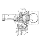
- The invention is described in detail below with reference to the appended drawing, which illustrates an axial section through a preferred embodiment of a drainage rate transmitter in accordance with the present invention.
- The drainage rate transmitter 1 illustrated on the drawing includes a cylindrical sampling piston housing 4, fixable to an
opening 3 made in a pipe 2 or a vessel with agitated contents. The housing 4 concentrically accommodates a sampling position and a retracted position with the aid of a piston rod means 7 attached to itsouter end portion 6, the piston rod being associated with apneumatic cylinder 8. There is a sample chamber 9 in thepiston 5 in the form of a through- hole transverse the longitudinal direction of thepiston 5, and when the piston is in its retracted position inside the housing 4 the chamber 9 forms part of a measuring space and has its axis coinciding with those of two holes 10 and 11 in the cylindrical surface of the housing 4. As with the sample chamber 9 these holes are also preferably cylindrically formed and of the same diameter as the chamber 9. The upper hole 10 continues into aspace 13 defined by a cylindrical wall 14 of the same diameter as the hole 10 and by anend wall 12. Thespace 13, hole 10, sample chamber 9 and hole 11 thus form a continuous chamber, such as to avoid dead spaces which can give rise to collections of fibres from different samplings. A measuring water nozzle 15 opens out into thespace 13, and the nozzle is in communication with a water supply via a valve 16. Thespace 13 is in communication with an outlet 17 via a hole in theend wall 12, this communication being regulated by anoutlet valve 18. - For eliminating rotation of the
sampling piston 5 in relation to the housing 4, thepiston rod 7 may be exchanged for two mutually parallel partial piston rods, or attached, as illustrated on the drawing, to theoutward end portion 6 of thepiston 5 at a point situated at a distance from the axis of thepiston 5. - The drainage rate transmitter in accordance with the present invention is suitably used for sampling suspensions which have . a concentration of about 1-10%, and for the cases where the permeability of a sample, liberated from smaller fibre fragments is to be determined. The lower hole 1 of the housing 4 opens out into a mixing and
dilution chamber 35 formed by acasing 32 which has twoopposing openings 33, 34, of which the upper 33 fits sealingly into the hole 11 and the lower 34 is adapted to seal against anend member 23 carrying ascreening plate 22. Theend member 23 includes adrainage collecting duct 24 arranged under thescreening plate 22, the duct opening out conically in the area under the screening plate. Via a dewateringvalve 25 theduct 24 is in communication with ameasuring glass 26 containing twoelectrodes 27, 28, and in an area directly under its conical portion is connected to a flushing water supply via avalve 29. Themeasuring glass 26 may be emptied via anoutlet 31 and anoutflow control valve 30. Depending on the pulp concentration, the length of thecasing 32 may be varied with a variation in the volume of the mixing chamber as a result. Dilution of the suspension sample may be carried out to give it a suitable concentration level with the aid of the variation in volume of themixing chamber 35 between the housing 4 andend member 23. The intention with the dilution is to arrive at a concentration level in the sample where the pulp flocking properties are reduced, and also to facilitate separation of smaller fibre fragments. With higher concentrations the pulp sample is usually heavily flocked, which affects the measurement procedure, since waterways are formed between the flocks, causing the measuring water to flow in the waterways between the flocks and in turn cause an unsteady output signal, which may give a faulty measuring result. The measuring result is considerably improved when the pulp is diluted down to about 0.8% or lower, with the aid of a mixing and dilution chamber of appropriate volume. For mixing during the dilution of the sample to the desired concentration and also for achieving sufficient turbulence for taking away the fine fraction there is a mixing or agitatingpropeller 36 in themixing chamber 35, the propeller being driven by amotor 37. The revolutionary speed of the motor and the implementation of thepropeller 36 are such that during the simultaneous introducion of measuring water at a suitable pressure such large shearing forces may be achieved at thescreening plate 22 that a pulp plug is not formed. Short fibre fragments can thus be separated by passing through the perforations in thescreening plate 22. - It is desirable, inter alia for cleaning purposes, quickly and easily to remove the
upper end wall 12,casing 32 andend member 23 with thescreening plate 22. This is enabled with the end of suitably placed, unillustrated toggle catches. - The measuring procedure in accordance with the present invention and using the equipment described hereinbefore, when the suspension sample has a pulp concentration of about 1-10%, or when measurement of the drainability properties of the entire pulp as well as those of the long fibre content takes place, is performed in the following manner:
- The
pneumatic cylinder 8 is activated so that thesampling piston 5 is thrust into the pipe 2 simultaneously as theoutflow control valve 30 under themeasuring glass 26 andoutlet valve 18 are open and the flushingwater valve 29, measuring water valve 16 anddewatering valve 25 under thescreening plate 22 are closed. This means that themixing chamber 35, which also serves as a measure chamber, is filled with water to the bottom edge of thepiston 5. Superfluous water runs out through avent 38 in the outer end portion of the housing 4. When sampling is finished, thepiston 5 has been completely retracted into its retracted position and mixing begins. - All the valves have the same operational status as under A. The sample taken out of the pipe 2 with the aid of the
piston 5 is mixed with the water in themixing chamber 35 with the aid of thepropeller 36. Mixing conditions may vary depending on the pulp concentration, as mentioned previously. The intention with dilution is to obtain a concentration level in which the flocking properties of the pulp are heavily reduced, which is the case when the concentration is at about 0.8% or less. - The
outer valve 18 is closed and the measuring water valve 16 and thedewatering valve 25 under thescreening plate 22 are opened. Theoutflow control valve 30 under themeasuring glass 26 is still open and the flushingwater valve 29 still closed. This means that during draining, which takes place in themixing chamber 35, the fibres in the suspension are deposited on thescreening plate 22 to form a pulp bed, with the aid of the measuring water. The drained water goes through the pulp on thescreening plate 22 via theoutflow control valve 30 under the measuring glass and out through theoutlet 31. - Excepting the
outflow control valve 30 under themeasuring glass 26, all the valves have the same operational status as under C. Theoutflow control valve 30 is now closed. This means that the drainage which passes through the pulp on thescreening plate 22 is collected in themeasuring glass 26, where the rising time between theelectrodes 27, 28 is measured for determining the permeability and/or the freeness level in the sample. This measurement can be repeated at one or more different pressures, with possible intermediate slushing. - All valves are closed. The
propeller 36 is activated and the fibre bed formed is slushed up again. - The smaller fibre fragments and fine material are separated by the valves being put into the operational state as in item C while the
propeller 36 is still activated. There are thus obtained sufficiently large shearing forces to prevent the formation of a fibre bed. The perforations in the . screeningplate 22 therefore allow passage of fine material, which is thus removed from the sample. - Measurement according to item D is carried out on the sample impoverished of fine material. When the measuring result has been registered the pressure can be varied, if so required, and a new measurement carried out at a different pressure. This measurement can be carried out with or without an intermediate slushing according to item E. The measuring values now obtained are subsequently compared with the measuring value or values obtained according to item D to determine the content of fine fraction in the pulp suspension.
- The flushing
water valve 29 and theoutlet valve 18 are opened. Simultaneous with closing the measuring water valve 16 and thedewatering valve 25 under thescreening plate 22, while theoutflow control valve 30 under the measuringglass 26 is open so that the measuring water in the measuringglass 26 can be tapped off. When flushing is terminated, the flushingwater valve 29 is closed and the water remaining in thechamber 35 is used to dilute the next sample. A new sample can now be taken.
Claims (1)
- Method based on permeability measurements for determining the drainage properties of a suspension particularly a fibre suspension, flowing through a pipe (2), with the aid of a drainage rate transmitter including a sampling piston housing (4) mounted in an opening (3) made in the wall of the pipe (2), the housing being open towards the interior of the pipe (2) and accommodating concentrically an axially displaceable sampling piston (5), adapted for taking out a suspension sample and supplying it into a mixing and dilution chamber (35), in which there is an agitating or mixing device (36), said chamber being provided with a screening plate (22), through which measuring water is transported to following measuring means (26-28) for determining permeability of the sample, said method comprising a first step of taking a pulp sample from the fibre suspension flowing in the pipe (2) and introducing it into the mixing and dilution chamber (35) with mixing being carried out with the aid of said mixing device (36), a second step of terminating the agitation after a predetermined time and forming a pulp bed on the screening plate (22) with the aid of preferably pressure controlled measuring water and a third step of determining the permeability of the sample with the aid of the pulp bed by allowing water to pass through the bed and the screening plate (22), characterized in that during the third step a given quantity of water is allowed to pass through the wholly or partially ready-formed pulp bed and the screening plate (22) at one or more pressure drops, possibly with intermediate slushing-up and reformation of the bed, said water being taken from under the plate (22) to said following measuring means (26-28) for determining a first measurement value, that subsequent thereto the pulp bed is slushed up from the screening plate (22) into suspension with the aid of an agitation by said mixing device (36), whereupon a flow of water is added, smaller fibre fragments thus being separated from the sample to pass through the screening plate (22), that the sample depleted of fine fraction is reformed against the screening plate (22) after washing has terminated, the permeability of the pulp bed on the screening plate (22) then being measured during one or more pressure drops, possibly with intermediate slushing-up and reformation, for determining a second measurement value and that both the values obtained are subsequently compared for determining not only the permeability of the pulp suspension but also the quantity of fine fraction in the pulp suspension.
Priority Applications (1)
| Application Number | Priority Date | Filing Date | Title |
|---|---|---|---|
| AT84902108T ATE52336T1 (en) | 1983-05-11 | 1984-05-11 | PROCEDURE FOR MEASURING PERMEABILITY. |
Applications Claiming Priority (2)
| Application Number | Priority Date | Filing Date | Title |
|---|---|---|---|
| SE8302719A SE436602B (en) | 1983-05-11 | 1983-05-11 | PROCEDURE FOR DETERMINING THE DRAINAGE CHARACTERISTICS THROUGH A PIPE CIRCULATING SUSPENSION, IN PARTICULAR FIBER SUSPENSION |
| SE8302719 | 1983-05-11 |
Publications (2)
| Publication Number | Publication Date |
|---|---|
| EP0168403A1 EP0168403A1 (en) | 1986-01-22 |
| EP0168403B1 true EP0168403B1 (en) | 1990-04-25 |
Family
ID=20351179
Family Applications (1)
| Application Number | Title | Priority Date | Filing Date |
|---|---|---|---|
| EP84902108A Expired EP0168403B1 (en) | 1983-05-11 | 1984-05-11 | Method for permeability measurement |
Country Status (7)
| Country | Link |
|---|---|
| US (1) | US4635470A (en) |
| EP (1) | EP0168403B1 (en) |
| JP (1) | JPS60501270A (en) |
| DE (1) | DE3482056D1 (en) |
| FI (1) | FI81912C (en) |
| SE (1) | SE436602B (en) |
| WO (1) | WO1984004591A1 (en) |
Cited By (1)
| Publication number | Priority date | Publication date | Assignee | Title |
|---|---|---|---|---|
| DE29713919U1 (en) * | 1997-08-05 | 1997-10-09 | Hoechst Marion Roussel De Gmbh | Device for removing solids from pressure-superimposed systems |
Families Citing this family (12)
| Publication number | Priority date | Publication date | Assignee | Title |
|---|---|---|---|---|
| US5186792A (en) * | 1989-07-19 | 1993-02-16 | Kyoritsu Electric Corporation | Apparatus for making dry sheet-like sample of solid particles from a suspension |
| US5319987A (en) * | 1992-04-17 | 1994-06-14 | Jeffrey Vassel | Sample collecting apparatus |
| SE503720C2 (en) * | 1994-02-28 | 1996-08-12 | Sunds Defibrator Ind Ab | Methods and apparatus for continuous sampling for analysis of a material mixture |
| SE9401956L (en) * | 1994-06-05 | 1995-12-06 | Arne Lindahl | Measurement of drainage and resilience properties |
| US5637808A (en) * | 1995-11-30 | 1997-06-10 | Jaeger; Ben E. | Liquid product sampler |
| US6564657B1 (en) * | 1996-05-30 | 2003-05-20 | Markku Mustonen | Sampling method and apparatus for consistency measurement |
| US5844152A (en) * | 1997-02-28 | 1998-12-01 | Thompson Equipment Company, Inc. | Serviceable measuring device |
| US6886420B2 (en) * | 2001-02-01 | 2005-05-03 | Rhe Haendel Engineering Gmbh & Co Kg | Sampling apparatus |
| SE520622C2 (en) * | 2002-01-25 | 2003-08-05 | Btg Kaelle Inventing Ab | Method and apparatus for measuring concentrations |
| US8365617B2 (en) | 2010-06-25 | 2013-02-05 | Mettler-Toledo Ag | Sampling device |
| US8312780B2 (en) | 2010-06-25 | 2012-11-20 | Mettler-Toledo Ag | Sampling device and method |
| FI129064B (en) * | 2020-05-19 | 2021-06-15 | Valmet Automation Oy | Apparatus for collecting dust samples |
Family Cites Families (10)
| Publication number | Priority date | Publication date | Assignee | Title |
|---|---|---|---|---|
| US1966712A (en) * | 1930-06-10 | 1934-07-17 | Fisher Flouring Mills Co | Grain sampling device |
| US1970521A (en) * | 1931-04-25 | 1934-08-14 | Gardner Richardson Co | Freeness tester |
| US3847022A (en) * | 1973-05-29 | 1974-11-12 | Seismograph Service Corp | Slurry sampler for polymer separation |
| BE822079A (en) * | 1973-11-29 | 1975-03-03 | VOLUMETRIC COLLECTOR OF FLUID MATERIAL SAMPLES | |
| SE384269B (en) * | 1975-04-10 | 1976-04-26 | Kaelle Regulatorer Ab | APPLY THAT WHEN AN APPARATUS FOR DETERMINATION OF THE MOLDING DEGREE OF A FIBER SUSPENSION THROUGH A PIPE PIPE SUSPENSED FROM A SAMPLE |
| JPS597944B2 (en) * | 1975-04-18 | 1984-02-21 | 本州製紙株式会社 | Method and device for measuring freeness of papermaking raw materials |
| US4262533A (en) * | 1979-05-03 | 1981-04-21 | Jaeger Ben E | Heated liquid sampler |
| SE417645B (en) * | 1979-05-23 | 1981-03-30 | Svenska Traeforskningsinst | Arrangement for taking samples from a suspension flowing through a pipe section |
| US4269064A (en) * | 1979-05-31 | 1981-05-26 | Johnson Julius T | On-line sampler |
| US4475410A (en) * | 1982-11-26 | 1984-10-09 | Jaeger Ben E | Sampler for viscous materials |
-
1983
- 1983-05-11 SE SE8302719A patent/SE436602B/en not_active IP Right Cessation
-
1984
- 1984-05-11 DE DE8484902108T patent/DE3482056D1/en not_active Expired - Lifetime
- 1984-05-11 WO PCT/SE1984/000177 patent/WO1984004591A1/en active IP Right Grant
- 1984-05-11 US US06/694,389 patent/US4635470A/en not_active Expired - Lifetime
- 1984-05-11 JP JP59502018A patent/JPS60501270A/en active Granted
- 1984-05-11 EP EP84902108A patent/EP0168403B1/en not_active Expired
-
1985
- 1985-06-10 FI FI852310A patent/FI81912C/en not_active IP Right Cessation
Cited By (1)
| Publication number | Priority date | Publication date | Assignee | Title |
|---|---|---|---|---|
| DE29713919U1 (en) * | 1997-08-05 | 1997-10-09 | Hoechst Marion Roussel De Gmbh | Device for removing solids from pressure-superimposed systems |
Also Published As
| Publication number | Publication date |
|---|---|
| US4635470A (en) | 1987-01-13 |
| SE436602B (en) | 1985-01-07 |
| FI81912B (en) | 1990-08-31 |
| JPS60501270A (en) | 1985-08-08 |
| WO1984004591A1 (en) | 1984-11-22 |
| SE8302719D0 (en) | 1983-05-11 |
| JPH0435020B2 (en) | 1992-06-09 |
| FI852310A0 (en) | 1985-06-10 |
| FI81912C (en) | 1990-12-10 |
| EP0168403A1 (en) | 1986-01-22 |
| FI852310L (en) | 1985-06-10 |
| SE8302719L (en) | 1984-11-12 |
| DE3482056D1 (en) | 1990-05-31 |
Similar Documents
| Publication | Publication Date | Title |
|---|---|---|
| EP0168403B1 (en) | Method for permeability measurement | |
| CA1071892A (en) | Method and apparatus for accurately measuring the freeness of paper stock in a short time | |
| KR940001648B1 (en) | Method for recycling wash residue of ready mixed concrete and system therefor | |
| US4836017A (en) | Method and apparatus for determining oil content of oil well production | |
| US4299495A (en) | Density meter | |
| EP1331480B1 (en) | A method and a device for measuring concentrations | |
| FI57664C (en) | SAETT ATT VID EN MALGRADSPROVARE UTTAGA ETT SUSPENSIONSPROV FOER BILDANDE AV EN FILTRERANDE FIBERKAKA SAMT HAERFOER AVSEDD ANORDNING | |
| CN109115656A (en) | A kind of device and method of automatic measurement consistency of mortar | |
| US6125688A (en) | Method of determining pulp properties | |
| US3456494A (en) | Method and apparatus for determining the viscosity of fluids | |
| CA1231553A (en) | Apparatus and method for permeability measurement | |
| CN212646264U (en) | Pollute plot soil sample analytical equipment | |
| US3946596A (en) | Leaf filter test and apparatus | |
| US3464272A (en) | Continuous slurry sampler and deaerator | |
| US6018989A (en) | Method and apparatus for measuring the properties of a fiber or colloid suspension | |
| JPH0625991A (en) | Pulsation type method for preparing sheet and its apparatus | |
| US4344321A (en) | Slurry measuring apparatus | |
| CN209043747U (en) | A kind of coal-water fluid concentration on-line measuring device | |
| CN219224468U (en) | Sand mud content measuring device | |
| SU1488018A1 (en) | Device for determining flotation reagents consumption | |
| CN100462721C (en) | Instrument for determining retention and drainage of fibrous suspensions | |
| GB2028164A (en) | Device for introducing samples into analyzer of apparatus for granulometric analysis of particles contained in fluids | |
| CN108367215A (en) | Equipment for filtering suspended matter | |
| KR20030005606A (en) | An analyzer of papermaking process;RDA-HSF(Retention & Drainage Analyzer - Handsheet Former) | |
| SU581411A1 (en) | Mechanical pulp sampler |
Legal Events
| Date | Code | Title | Description |
|---|---|---|---|
| PUAI | Public reference made under article 153(3) epc to a published international application that has entered the european phase |
Free format text: ORIGINAL CODE: 0009012 |
|
| AK | Designated contracting states |
Designated state(s): AT BE CH DE FR GB LI LU NL SE |
|
| 17P | Request for examination filed |
Effective date: 19851116 |
|
| RBV | Designated contracting states (corrected) |
Designated state(s): AT DE FR GB |
|
| 17Q | First examination report despatched |
Effective date: 19870710 |
|
| RAP1 | Party data changed (applicant data changed or rights of an application transferred) |
Owner name: BTG KAELLE INVENTING AKTIEBOLAG |
|
| GRAA | (expected) grant |
Free format text: ORIGINAL CODE: 0009210 |
|
| AK | Designated contracting states |
Kind code of ref document: B1 Designated state(s): AT DE FR GB |
|
| PG25 | Lapsed in a contracting state [announced via postgrant information from national office to epo] |
Ref country code: FR Effective date: 19900425 Ref country code: AT Effective date: 19900425 |
|
| REF | Corresponds to: |
Ref document number: 52336 Country of ref document: AT Date of ref document: 19900515 Kind code of ref document: T |
|
| REF | Corresponds to: |
Ref document number: 3482056 Country of ref document: DE Date of ref document: 19900531 |
|
| PG25 | Lapsed in a contracting state [announced via postgrant information from national office to epo] |
Ref country code: GB Effective date: 19900625 |
|
| EN | Fr: translation not filed | ||
| PLBE | No opposition filed within time limit |
Free format text: ORIGINAL CODE: 0009261 |
|
| STAA | Information on the status of an ep patent application or granted ep patent |
Free format text: STATUS: NO OPPOSITION FILED WITHIN TIME LIMIT |
|
| GBPC | Gb: european patent ceased through non-payment of renewal fee | ||
| 26N | No opposition filed | ||
| PGFP | Annual fee paid to national office [announced via postgrant information from national office to epo] |
Ref country code: DE Payment date: 20020522 Year of fee payment: 19 |
|
| PG25 | Lapsed in a contracting state [announced via postgrant information from national office to epo] |
Ref country code: DE Free format text: LAPSE BECAUSE OF NON-PAYMENT OF DUE FEES Effective date: 20031202 |