EP0168153A2 - Crankshaft for an internal combustion engine - Google Patents
Crankshaft for an internal combustion engine Download PDFInfo
- Publication number
- EP0168153A2 EP0168153A2 EP85303835A EP85303835A EP0168153A2 EP 0168153 A2 EP0168153 A2 EP 0168153A2 EP 85303835 A EP85303835 A EP 85303835A EP 85303835 A EP85303835 A EP 85303835A EP 0168153 A2 EP0168153 A2 EP 0168153A2
- Authority
- EP
- European Patent Office
- Prior art keywords
- crankshaft
- main
- flywheel
- groove
- journal
- Prior art date
- Legal status (The legal status is an assumption and is not a legal conclusion. Google has not performed a legal analysis and makes no representation as to the accuracy of the status listed.)
- Pending
Links
Images


Classifications
-
- F—MECHANICAL ENGINEERING; LIGHTING; HEATING; WEAPONS; BLASTING
- F16—ENGINEERING ELEMENTS AND UNITS; GENERAL MEASURES FOR PRODUCING AND MAINTAINING EFFECTIVE FUNCTIONING OF MACHINES OR INSTALLATIONS; THERMAL INSULATION IN GENERAL
- F16C—SHAFTS; FLEXIBLE SHAFTS; ELEMENTS OR CRANKSHAFT MECHANISMS; ROTARY BODIES OTHER THAN GEARING ELEMENTS; BEARINGS
- F16C3/00—Shafts; Axles; Cranks; Eccentrics
- F16C3/04—Crankshafts, eccentric-shafts; Cranks, eccentrics
- F16C3/06—Crankshafts
-
- F—MECHANICAL ENGINEERING; LIGHTING; HEATING; WEAPONS; BLASTING
- F16—ENGINEERING ELEMENTS AND UNITS; GENERAL MEASURES FOR PRODUCING AND MAINTAINING EFFECTIVE FUNCTIONING OF MACHINES OR INSTALLATIONS; THERMAL INSULATION IN GENERAL
- F16C—SHAFTS; FLEXIBLE SHAFTS; ELEMENTS OR CRANKSHAFT MECHANISMS; ROTARY BODIES OTHER THAN GEARING ELEMENTS; BEARINGS
- F16C2360/00—Engines or pumps
- F16C2360/22—Internal combustion engines
Definitions
- the present invention relates to a crankshaft for an internal combustion engine.
- a crankshaft a comprises crank arms e and h, connecting-rod journals (crankpin) f and g, and a main-bearing journal d which is connected to a flywheel b.
- crankshaft a of a four-cylinder in-line engine for example, crank arm e of the fourth cylinder adjacent to the flywheel b, connecting-rod journal f, crank arm h, and connecting-rod journal g of the third cylinder are deflected by the force as shown by the broken line E in Figure 4a.
- the bending of the crankshaft is schematically indicated in Figure 4b by a broken line C in relation to the axis of the crankshaft shown by a broken line D. It will be seen that the crankshaft is bent at a point B. In other words, at the point B, which is the juncture of the fourth connecting-rod journal f and the crank arm e, stress concentration occurs.
- the present invention seeks to provide a crankshaft which may overcome the above-mentioned problems and improve the fatigue limit and the strength of the crankshaft.
- the present invention provides a crankshaft for connection by an end to a flywheel in an internal combustion engine, the crankshaft having a main-bearing journal at the end where the crankshaft and flywheel connect, and characterised by a groove at the periphery of the main-bearing journal, whereby when the crankshaft is subject to a bending force the shaft can flex at the groove.
- a plurality of arcuate grooves are formed on the main-bearing journal.
- a crankshaft of a four-cylinder in-line combustion engine generally indicated by the numeral 1 has a flywheel 6 secured thereto at an output end, and a drive pulley 7 mounted on the other end thereof.
- the crankshaft 1 is supported at a first main-bearing journal 21, second main-bearing journal 22, and a third main-bearing journal 23 by main bearings 91, 92 and 93 provided in bulkheads 81, 82 and 83.
- a first connecting-rod journal 31, second connecting-rod journal 32, third connecting-rod journal 33 and fourth connecting-rod journal 34 are formed on the crankshaft at ends of crank arms 41 to 46, respectively.
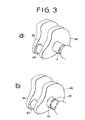
- annular groove 5 formed on the periphery of the third main-bearing journal 23 adjacent to the flywheel 6 is an annular groove 5, the inside diameter of which is made to maintain sufficient strength in the crankshaft.
- the bottom of the groove 5 has an arcuate portion in longitudinal section of the main-bearing journal 23.
- crankshaft 1 constructed as explained above will now be explained.
- a crankshaft having the heavy flywheel at its output end may be subject to great stresses at the point B of Figure 4a. In the embodiment of the present invention, such stresses are diverged by the function of the annular groove 5.
- crankshaft is bent at the point F and the deflection is shown by line C' (broken line) with respect to the axis D of the crankshaft (a chain line).
- line C' broken line
- the stresses conventionally concentrated at the point B of the crankshaft is now divided between two positions, i.e. the point B and the point F by the provision of the annular groove 5.
- the stress at the juncture B is reduced compared with the conventional crankshaft, so that the fatigue limit at the point B is improved.
- the third main-bearing journal 23 is made sufficiently strong despite the annular groove 5, the strength and rigidity of the crankshaft is maintained.
- annular groove 5 is formed on the whole of the periphery of the third main-bearing journal 23 in the first embodiment of the present invention, a plurality of arcuate grooves 51 and 52 may be provided as shown in Figure 3b, so as to divert the stress at the juncture B.
- the present invention provides a crankshaft having, at an end adjacent a flywheel, a journal provided with an annular groove so as to diverge stresses.
- the crankshaft of the present invention can be employed in an engine having large torque and large output.
- the crankshaft can be made light in weight and simple in construction.
Abstract
Description
- The present invention relates to a crankshaft for an internal combustion engine.
- In a conventional internal combustion engine, stress concentration occurs in the juncture of a crank arm and a crankpin which receives a connecting-rod of a piston, adjacent to a flywheel. In order to prevent the concentration of stresses, heretofore various improvements on shape, material, and manufacturing process of the crankshaft have been proposed.
- Factors causing such stress concentration are explained hereinafter with reference to Figures 4a and 4b. In Figure 4a, a crankshaft a comprises crank arms e and h, connecting-rod journals (crankpin) f and g, and a main-bearing journal d which is connected to a flywheel b. When a force is applied in the direction A to the connecting-rod journal f through a connecting-rod (not shown) for an end cylinder adjacent to the flywheel b, the flywheel b and the main-bearing journal d adjacent to the flywheel b are hardly deflected because of their great masses. On the other hand, in the case of crankshaft a of a four-cylinder in-line engine, for example, crank arm e of the fourth cylinder adjacent to the flywheel b, connecting-rod journal f, crank arm h, and connecting-rod journal g of the third cylinder are deflected by the force as shown by the broken line E in Figure 4a. The bending of the crankshaft is schematically indicated in Figure 4b by a broken line C in relation to the axis of the crankshaft shown by a broken line D. It will be seen that the crankshaft is bent at a point B. In other words, at the point B, which is the juncture of the fourth connecting-rod journal f and the crank arm e, stress concentration occurs. Such stress may cause the crankshaft to be bent or to fracture. In order to prevent such failures, Japanese Utility Model Laid Open 56-49312 and Japanese Patent Laid Open 59-16126, for example, suggest improving the rigidity and strength of the crankshaft by increasing sectional areas of appropriate portions of the crankshaft. However, some problems remain, for example: the mass of the crankshaft is increased by the reinforcement; stress concentration still occurs in spite of the reinforcement; and design and manufacturing process of the crankshaft become more complicated.
- Therefore, the present invention seeks to provide a crankshaft which may overcome the above-mentioned problems and improve the fatigue limit and the strength of the crankshaft.
- The present invention provides a crankshaft for connection by an end to a flywheel in an internal combustion engine, the crankshaft having a main-bearing journal at the end where the crankshaft and flywheel connect, and characterised by a groove at the periphery of the main-bearing journal, whereby when the crankshaft is subject to a bending force the shaft can flex at the groove.
- In one embodiment of the present invention, a plurality of arcuate grooves are formed on the main-bearing journal.
- Preferred embodiment of the present invention will now be described, by way of example and with reference to the accompanying drawings, wherein:
- Figures 1 shows the construction of a crankshaft of an internal combustion engine according to a preferred embodiment of the present invention;
- Figure 2a shows the bending of the crankshaft of Figure 1;
- Figure 2b schematically shows the bending of the crankshaft shown in Figure 2a; .
- Figure 3a is a perspective view showing a part of the crankshaft of Figure 1;
- Figure 3b is a similar view to the Figure 3a but shows another embodiment of the present invention;
- Figure 4a shows a part of a conventional crankshaft; and
- Figure 4b schematically shows the bending of the crankshaft of Figure 4a.
- Referring to Figures 1 to 3, a crankshaft of a four-cylinder in-line combustion engine, generally indicated by the numeral 1 has a
flywheel 6 secured thereto at an output end, and a drive pulley 7 mounted on the other end thereof. The crankshaft 1 is supported at a first main-bearingjournal 21, second main-bearingjournal 22, and a third main-bearingjournal 23 bymain bearings bulkheads rod journal 31, second connecting-rod journal 32, third connecting-rod journal 33 and fourth connecting-rod journal 34 are formed on the crankshaft at ends ofcrank arms 41 to 46, respectively. - As shown in detail in Figure 3a, formed on the periphery of the third main-bearing
journal 23 adjacent to theflywheel 6 is anannular groove 5, the inside diameter of which is made to maintain sufficient strength in the crankshaft. The bottom of thegroove 5 has an arcuate portion in longitudinal section of the main-bearingjournal 23. - The function of the crankshaft 1 constructed as explained above will now be explained. As mentioned above, a crankshaft having the heavy flywheel at its output end may be subject to great stresses at the point B of Figure 4a. In the embodiment of the present invention, such stresses are diverged by the function of the
annular groove 5. - Referring to Figure 2a, when a force is applied to the fourth connecting-
rod journal 34 in the direction of the arrow A through the connecting-rod (not shown) of the piston, themassive flywheel 6 is hardly deflected, but the third main-bearingjournal 23 of the crankshaft 1,arm 46, fourth connecting-rod journal 34,arm 45, and third connecting-rod journal 33 may be deflected as shown by the broken line E in Figure 2a. However, the stresses are divided between two positions, one of which is the juncture B of the fourth connecting-rod journal 34 and thearm 46 and the other is a point F in the bottom of theannular groove 5 of the third main-bearingjournal 23. As shown in Figure 2b, the crankshaft is bent at the point F and the deflection is shown by line C' (broken line) with respect to the axis D of the crankshaft (a chain line). Accordingly, the stresses conventionally concentrated at the point B of the crankshaft is now divided between two positions, i.e. the point B and the point F by the provision of theannular groove 5. Thus, the stress at the juncture B is reduced compared with the conventional crankshaft, so that the fatigue limit at the point B is improved. Further, since the third main-bearingjournal 23 is made sufficiently strong despite theannular groove 5, the strength and rigidity of the crankshaft is maintained. - Although the
annular groove 5 is formed on the whole of the periphery of the third main-bearingjournal 23 in the first embodiment of the present invention, a plurality ofarcuate grooves - From the foregoings, it is now clear that the present invention provides a crankshaft having, at an end adjacent a flywheel, a journal provided with an annular groove so as to diverge stresses. Thus, the crankshaft of the present invention can be employed in an engine having large torque and large output. Further, when used in an engine of the same torque and output as the conventional engine, the crankshaft can be made light in weight and simple in construction.
Claims (5)
Applications Claiming Priority (2)
| Application Number | Priority Date | Filing Date | Title |
|---|---|---|---|
| JP59141758A JPS6121413A (en) | 1984-07-09 | 1984-07-09 | Crankshaft of internal-combustion engine |
| JP141758/84 | 1984-07-09 |
Publications (2)
| Publication Number | Publication Date |
|---|---|
| EP0168153A2 true EP0168153A2 (en) | 1986-01-15 |
| EP0168153A3 EP0168153A3 (en) | 1986-12-30 |
Family
ID=15299504
Family Applications (1)
| Application Number | Title | Priority Date | Filing Date |
|---|---|---|---|
| EP85303835A Pending EP0168153A3 (en) | 1984-07-09 | 1985-05-30 | Crankshaft for an internal combustion engine |
Country Status (3)
| Country | Link |
|---|---|
| EP (1) | EP0168153A3 (en) |
| JP (1) | JPS6121413A (en) |
| DE (1) | DE168153T1 (en) |
Cited By (4)
| Publication number | Priority date | Publication date | Assignee | Title |
|---|---|---|---|---|
| FR2847314A1 (en) * | 2002-11-14 | 2004-05-21 | Renault Sa | Automobile engine crankshaft comprises crank arm delimited by lateral faces and axial cylindrical sections delimited by convex machined surface delimiting annular connection zone and comprising stress discharge groove |
| FR2885187A1 (en) * | 2005-04-28 | 2006-11-03 | Renault Sas | Internal combustion engine`s crankshaft for motor vehicle, has annular connection zone with increased width and depth in zone, where constraints are high, to form discharge groove that is interfaced with cylindrical carrier |
| EP2730791A1 (en) * | 2012-11-09 | 2014-05-14 | MAN Diesel & Turbo, filal af MAN Diesel & Turbo SE, Tyskland | Crankshaft, bearing assembly and large multi-cylinder two-stroke diesel engine |
| US20150247525A1 (en) * | 2012-09-24 | 2015-09-03 | Thyssenkrupp Matalúrgica Campo Limpo Ltda. | Weight optimized crank-shaft |
Families Citing this family (1)
| Publication number | Priority date | Publication date | Assignee | Title |
|---|---|---|---|---|
| CN106514161B (en) * | 2016-11-04 | 2018-09-11 | 安徽江淮汽车集团股份有限公司 | The processing method and engine crankshaft of engine crankshaft |
Citations (2)
| Publication number | Priority date | Publication date | Assignee | Title |
|---|---|---|---|---|
| FR799099A (en) * | 1935-03-01 | 1936-06-05 | Anciens Etablissements Panhard | Improvement in crankshafts of internal combustion engines |
| DE2160586A1 (en) * | 1971-12-07 | 1973-06-14 | Schmidt Gmbh Karl | CRANKSHAFT |
-
1984
- 1984-07-09 JP JP59141758A patent/JPS6121413A/en active Pending
-
1985
- 1985-05-30 DE DE198585303835T patent/DE168153T1/en active Pending
- 1985-05-30 EP EP85303835A patent/EP0168153A3/en active Pending
Patent Citations (2)
| Publication number | Priority date | Publication date | Assignee | Title |
|---|---|---|---|---|
| FR799099A (en) * | 1935-03-01 | 1936-06-05 | Anciens Etablissements Panhard | Improvement in crankshafts of internal combustion engines |
| DE2160586A1 (en) * | 1971-12-07 | 1973-06-14 | Schmidt Gmbh Karl | CRANKSHAFT |
Cited By (6)
| Publication number | Priority date | Publication date | Assignee | Title |
|---|---|---|---|---|
| FR2847314A1 (en) * | 2002-11-14 | 2004-05-21 | Renault Sa | Automobile engine crankshaft comprises crank arm delimited by lateral faces and axial cylindrical sections delimited by convex machined surface delimiting annular connection zone and comprising stress discharge groove |
| FR2885187A1 (en) * | 2005-04-28 | 2006-11-03 | Renault Sas | Internal combustion engine`s crankshaft for motor vehicle, has annular connection zone with increased width and depth in zone, where constraints are high, to form discharge groove that is interfaced with cylindrical carrier |
| US20150247525A1 (en) * | 2012-09-24 | 2015-09-03 | Thyssenkrupp Matalúrgica Campo Limpo Ltda. | Weight optimized crank-shaft |
| EP2730791A1 (en) * | 2012-11-09 | 2014-05-14 | MAN Diesel & Turbo, filal af MAN Diesel & Turbo SE, Tyskland | Crankshaft, bearing assembly and large multi-cylinder two-stroke diesel engine |
| CN103807282A (en) * | 2012-11-09 | 2014-05-21 | 曼柴油机欧洲股份公司曼柴油机德国分公司 | Crankshaft, bearing assembly and large multi-cylinder two-stroke diesel engine |
| CN103807282B (en) * | 2012-11-09 | 2015-10-28 | 曼柴油机欧洲股份公司曼柴油机德国分公司 | Bent axle, bearing unit and large scale multi-cylinder body two stroke diesel engine |
Also Published As
| Publication number | Publication date |
|---|---|
| EP0168153A3 (en) | 1986-12-30 |
| DE168153T1 (en) | 1986-04-30 |
| JPS6121413A (en) | 1986-01-30 |
Similar Documents
| Publication | Publication Date | Title |
|---|---|---|
| KR920006622B1 (en) | Engine & low vibration crank shaft therefor | |
| US4463550A (en) | Silent chain | |
| US6237442B1 (en) | High value static unbalance-type balance shafts | |
| JPH04231716A (en) | Built-up type crankshaft for two cycle engine | |
| EP0168153A2 (en) | Crankshaft for an internal combustion engine | |
| GB2190169A (en) | Power transmission belt | |
| US20060090724A1 (en) | Crankshaft support structure of internal combustion engine | |
| KR100941204B1 (en) | A crankshaft for a ?-type internal combustion engine | |
| KR102201465B1 (en) | Cylinder block assembly | |
| US4622932A (en) | V-crankarm | |
| JPH08226432A (en) | Crank shaft | |
| KR100310085B1 (en) | Cross stroke for 2-stroke V-engine | |
| US9803685B2 (en) | Crankshaft | |
| EP0679229B1 (en) | A crankshaft for a twostroke internal combustion engine and a method for adjusting same | |
| SU699249A1 (en) | Bearing assembly of connecting-rod crank head | |
| US4708106A (en) | Acute angle crankarm transmitting reciprocating motion in a rotary fashion | |
| JP7425234B2 (en) | Large turbocharged 2-stroke uniflow crosshead crankshaft for internal combustion engines | |
| WO2016199711A1 (en) | Crankshaft for reciprocating engine | |
| JPH0435565Y2 (en) | ||
| US2359306A (en) | Engine crankshaft | |
| KR100513450B1 (en) | Mounting apparatus for crank shaft and connecting rod | |
| JPS629020A (en) | Crankshaft for multiple cylinder engine | |
| GB2342696A (en) | Longitudinally tapering single unbalance type engine balance shaft | |
| JPH07243433A (en) | Connecting rod | |
| SU1677385A1 (en) | Flexible shaft |
Legal Events
| Date | Code | Title | Description |
|---|---|---|---|
| PUAI | Public reference made under article 153(3) epc to a published international application that has entered the european phase |
Free format text: ORIGINAL CODE: 0009012 |
|
| 17P | Request for examination filed |
Effective date: 19850614 |
|
| AK | Designated contracting states |
Designated state(s): DE GB |
|
| DET | De: translation of patent claims | ||
| PUAL | Search report despatched |
Free format text: ORIGINAL CODE: 0009013 |
|
| AK | Designated contracting states |
Kind code of ref document: A3 Designated state(s): DE GB |
|
| STAA | Information on the status of an ep patent application or granted ep patent |
Free format text: STATUS: EXAMINATION IS IN PROGRESS |
|
| 17Q | First examination report despatched |
Effective date: 19880804 |
|
| RIN1 | Information on inventor provided before grant (corrected) |
Inventor name: OZAWA, MASAHIRO Inventor name: MATSUNAGA, SEIKI Inventor name: TAYAMA, MASAHIRO |