EP0168002A2 - Sliding arches for a tarpaulin - Google Patents
Sliding arches for a tarpaulin Download PDFInfo
- Publication number
- EP0168002A2 EP0168002A2 EP85108361A EP85108361A EP0168002A2 EP 0168002 A2 EP0168002 A2 EP 0168002A2 EP 85108361 A EP85108361 A EP 85108361A EP 85108361 A EP85108361 A EP 85108361A EP 0168002 A2 EP0168002 A2 EP 0168002A2
- Authority
- EP
- European Patent Office
- Prior art keywords
- sliding
- frame according
- tarpaulin
- tarpaulin frame
- longitudinal
- Prior art date
- Legal status (The legal status is an assumption and is not a legal conclusion. Google has not performed a legal analysis and makes no representation as to the accuracy of the status listed.)
- Withdrawn
Links
Images


Classifications
-
- B—PERFORMING OPERATIONS; TRANSPORTING
- B60—VEHICLES IN GENERAL
- B60J—WINDOWS, WINDSCREENS, NON-FIXED ROOFS, DOORS, OR SIMILAR DEVICES FOR VEHICLES; REMOVABLE EXTERNAL PROTECTIVE COVERINGS SPECIALLY ADAPTED FOR VEHICLES
- B60J7/00—Non-fixed roofs; Roofs with movable panels, e.g. rotary sunroofs
- B60J7/02—Non-fixed roofs; Roofs with movable panels, e.g. rotary sunroofs of sliding type, e.g. comprising guide shoes
- B60J7/04—Non-fixed roofs; Roofs with movable panels, e.g. rotary sunroofs of sliding type, e.g. comprising guide shoes with rigid plate-like element or elements, e.g. open roofs with harmonica-type folding rigid panels
- B60J7/041—Non-fixed roofs; Roofs with movable panels, e.g. rotary sunroofs of sliding type, e.g. comprising guide shoes with rigid plate-like element or elements, e.g. open roofs with harmonica-type folding rigid panels for utility vehicles, e.g. with slidable and foldable rigid panels
- B60J7/042—Non-fixed roofs; Roofs with movable panels, e.g. rotary sunroofs of sliding type, e.g. comprising guide shoes with rigid plate-like element or elements, e.g. open roofs with harmonica-type folding rigid panels for utility vehicles, e.g. with slidable and foldable rigid panels with a vertical lifting or folding movement
-
- B—PERFORMING OPERATIONS; TRANSPORTING
- B60—VEHICLES IN GENERAL
- B60J—WINDOWS, WINDSCREENS, NON-FIXED ROOFS, DOORS, OR SIMILAR DEVICES FOR VEHICLES; REMOVABLE EXTERNAL PROTECTIVE COVERINGS SPECIALLY ADAPTED FOR VEHICLES
- B60J7/00—Non-fixed roofs; Roofs with movable panels, e.g. rotary sunroofs
- B60J7/02—Non-fixed roofs; Roofs with movable panels, e.g. rotary sunroofs of sliding type, e.g. comprising guide shoes
- B60J7/06—Non-fixed roofs; Roofs with movable panels, e.g. rotary sunroofs of sliding type, e.g. comprising guide shoes with non-rigid element or elements
- B60J7/061—Non-fixed roofs; Roofs with movable panels, e.g. rotary sunroofs of sliding type, e.g. comprising guide shoes with non-rigid element or elements sliding and folding
- B60J7/062—Non-fixed roofs; Roofs with movable panels, e.g. rotary sunroofs of sliding type, e.g. comprising guide shoes with non-rigid element or elements sliding and folding for utility vehicles
Definitions
- the invention relates to a sliding roof tarpaulin frame, in particular for trucks and trailers, according to the preamble of claim 1.
- Sliding roofs are desirable for trucks and trailers, on the one hand to allow loading from above and on the other hand to completely cover the load during transport and to protect it against the weather.
- the sliding roof should be easy and quick to open and close. When opened, the loading area should be as free as possible.
- the tarpaulin frame should be quick and easy to dismantle and reassemble.
- the cross brackets are supported by scissor-like and movable support struts on roller carriages which can be moved on the longitudinal brackets designed as guide rails.
- the scissor-like support struts prevent the crossbars from one another in such a way that When the convertible top is opened, the scissors formed in pairs by the support struts close and the crossbars are pushed together while lifting.
- a cable drive that can be operated from the ground is used with a cable loop that is guided over deflection pulleys and a cable drum and is attached to the rearmost roller carriage.
- One of the deflection rollers must be arranged on the rear longitudinal end of the bow so that the rearmost roller carriage can be pulled back to the rear longitudinal bow when the sliding roof is closed.
- the crossbars of the known arrangement which are supported movably supported on the longitudinal bars via support strut scissor assemblies and roller carriages, naturally require a correspondingly complex and costly construction.
- the rear longitudinal bow end is necessary as a fixed point for the cable deflection of the cable drive used to open and close the sliding roof and, like the fact that the roller carriages are secured against lifting off on the longitudinal bow and the cross bow all through the support strut scissor arrangements with each other and with the Roller carriages are connected to the fact that, if necessary, dismantling and reconstruction of the tarpaulin frame is not very practical and, in particular, can hardly be carried out by the maximum of two men on a truck.
- the invention is based on the object to design a sliding roof tarpaulin frame of the type mentioned in such a way that it is light, simple and inexpensive construction, yet easy to open and close and can be assembled and dismantled by a truck crew alone without difficulty.
- a cable drive can be used in a manner known per se, the cable of which is attached to the rearmost cross bow and can be wound onto a cable drum arranged in the region of the front end of the loading area.
- a traction rope or the like which is also attached to the rearmost crossbar, is sufficient, by means of which the sliding roof can be pulled back into its closed position without the need for a cable drive.
- the individual cross brackets are connected to one another by flexible intermediate links, namely connecting belts or the like, which tighten when the convertible top is closed, and the correct mutual distances between the cross brackets are automatically set during the closing process.
- the construction according to the invention has the advantage of a very simple construction, consequently also a very inexpensive to manufacture, and in addition the entire construction is light in weight and can be easily disassembled or assembled at any time if, for example to facilitate the loading process, the tarpaulin frame is complete or should be partially removed. Since in the sliding roof tarpaulin frame according to the invention, because of its light construction, no double-acting cable drive is necessary to open and close, and therefore a cable deflection fixed point arranged at the rear longitudinal bow end as well as the other complicated cable deflection mechanics that are sensitive to sliding of the cable are unnecessary, assembly and disassembly are unnecessary of the tarpaulin frame considerably easier.
- the sliding bodies are preferably designed as sliding bodies which are connected to the transverse brackets so as to be rotatable about a vertical axis. This prevents the sliding bodies from tilting with respect to the guide rails even if a one-sided pull acts on the cross brackets when opening or closing, since then the sliding bodies can always run parallel to the guide rail, even if the cross brackets move somewhat obliquely in the course of their displacement should ask.
- the longitudinal bars are expediently designed as hollow-profile guide rails that receive the sliding bodies. As a result, the sliding bodies are protected against external influences at the same time.
- the sliding bodies are expediently designed as elongated prism bodies, the length of which is selected to be sufficiently large to reliably prevent tilting in the guide rails.
- the sliding bodies are preferably designed with sliding surfaces that extend over their entire length and interact with guide surfaces of the guide rails, but are partially designed such that they can be pushed into one another.
- the sliding bodies are formed at their two ends with mutually complementary cross-sectional profiles, in each of which part of their circumference is formed by a sliding surface.
- one end of this sliding body is fork-like and the other end is complementary web-like.
- diagonally offset Za p fenprofile or the like are possible.
- the sliding bodies are preferably made of low-friction plastic.
- the longitudinal bars of the tarpaulin frame can be divided and their length sections can be separated or connected by means of a quick coupling, so that a partial dismantling of the tarpaulin frame is also possible quickly and easily if necessary.
- the vertical supports are advantageously guided in and out of the hollow stanchions and can be locked in certain vertical positions.
- This type of height adjustability of a tarpaulin frame is already known per se (DE-OS 31 83 338).
- the invention therefore proposes sideways to be attached to the stanchions side wall closures, which consists of a bolt and two concentric, rotatable sleeves, the two sleeves are each provided with a lateral insertion slot for inserting the bolt.
- One of the two sleeves is provided with an actuator for turning, while one of the other two parts is attached to the side wall and the other to the hollow stanchion. If one sleeve is now rotated by means of the actuating member in such a way that the lateral insertion slots of both sleeves overlap, the bolt can be inserted or carried out, and the one sleeve is rotated so that the insertion slots of both sleeves no longer overlap until the inserted one Bolt locked in the sleeve arrangement.
- the bolt expediently has a head which is thickened in diameter, the rear end face of which cooperates with a corresponding axial shoulder of the inner sleeve in order to secure the bolt against axial sliding out of the sleeve arrangement.
- the actuating member can be a lever that can be bent in the closed position of the dropside lock and has a nose that engages in a corresponding opening of the stanchion when the lever is bent in order to secure the lever in the closed position of the sleeve arrangement.
- the tarpaulin frame according to the invention is preferably assigned a clamping device for fixing the tarpaulin to the side walls, which consists of a rotatable rod running at a distance along the side wall and of finger-like or cam-like clamping pieces rigidly connected therewith, which by rotating the Rod can be pivoted towards the side wall or away from it.
- a clamping device for fixing the tarpaulin to the side walls which consists of a rotatable rod running at a distance along the side wall and of finger-like or cam-like clamping pieces rigidly connected therewith, which by rotating the Rod can be pivoted towards the side wall or away from it.
- the longitudinal bow is provided with longitudinal guides for moving such pendulum partition walls in the longitudinal direction of the loading area.
- the pendulum partition walls can be moved on rollers on this longitudinal guide of the longitudinal bow. This allows a variable load compartment subdivision, with locking options for the pendulum partitions only having to be provided at certain short intervals.
- the pendulum partitions are locked with the aid of pins arranged on their lower edges and engaging in corresponding openings in the load compartment floor.
- the pendulum partitions are preferably suspended on the guides running along the longitudinal bars via eccentric crank mechanisms by means of which the pendulum partitions can optionally be raised to an unlocking position or a locking position can be lowered.
- the roller axis can serve as an eccentric crankshaft and can be rotated at its outer end by means of an insertable or insertable key, while an eccentric crank pin arranged thereon is designed as a hinge pin for the suspension of the pendulum partition walls and by rotating the eccentric crankshaft to a stop position above the top dead center is also pivotable so that the pendulum partition is in the raised position in a stable, easily movable position.
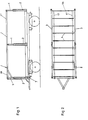
- FIG. 1 and 2 show a side view and top view of a sliding tarpaulin frame according to the invention on a truck trailer.
- the tarpaulin frame consists of vertical supports 1 arranged on both sides of the loading area, which can be extended and retracted in hollow stanchions 2 for the height adjustability of the tarpaulin frame and can be locked in certain height positions, further from two longitudinal bars 3 carried by the vertical supports 1 and a number of them Top view according to FIG. 2 visible cross bars 4 running between the two longitudinal bars 3.
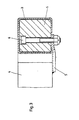
- the two longitudinal bows 3 are each designed as hollow profile guide rails, the cross-sectional profile of FIG. 3, for example, can be approximately square or rectangular, but can also be polygonal or circular in another way.
- Sliding bodies 5 with a corresponding cross-sectional profile are slidably guided in these guide rails, which are connected to the ends of the crossbars 4.
- the connection to the crossbar end in question takes place, for example, by means of a tab 5 fastened to the crossbar end and a bolt 6 which extends through a corresponding bore in the sliding body 5 and is attached to the tab 5 with its lower end.
- the bolt 6 is rotatably seated in the bore of the sliding body 5 and forms a hinge pin with a vertical axis, about which the sliding body 5 can be rotated. In this way, tilting of the slider 5 in the guide rail is avoided if the crossbar in question should be inclined somewhat from its exactly transverse position.
- the cross brackets 4 are all slidably guided in the manner just described via sliding bodies 5 in the longitudinal bow 3 designed as guide rails, the cross bow can be opened in order to open the top Push together towards the front end of the tarpaulin frame.
- a cable drive with a cranked cable drum 7 arranged in the floor area of the front loading space end can be used, which is shown in FIG. 1, the cable of which is attached to the rearmost cross bow 4a (see FIG. 2).
- This cable drive only works in the opening direction, but is extremely simple.
- a pull strap (not shown), which is also attached to the rearmost cross bow 4a, is sufficient, with which the driver can pull the convertible top back into its closed position.
- the individual cross brackets are connected to one another by connecting straps 41 or the like, so that when the top is closed the correct mutual distances of the cross brackets from one another are automatically set by tightening these connecting straps.
- sliding bodies 5 are intended to avoid tilting in the guide rails leading them and thereby to enable the crossbars to be moved easily, have a sufficient guide length, but on the other hand the transverse bow should be able to be pushed together as closely as possible to open the convertible top as far as possible.
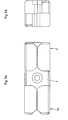
- the two possible embodiments of sliding bodies 5 shown take these two requirements into account in that they are partially collapsible without, however, reducing their guide length.
- one end 5a of the sliding body 5 is forked and the other end 5b of this sliding body is complementary thereto web-like design, so that the successive sliders can be partially pushed into one another.
- the upper sliding surface 51 and the lower sliding surface 52 (FIG. 4a) of this sliding body only extend over a little more than half the length of the sliding body, the effective length of the two lateral sliding surfaces 53, which counteract lateral tilting of the sliding body, corresponds to the full Sliding body length and thus result in optimal guidance.
- the design of the mutually complementary cross-sectional profiles of the two sliding body ends 5a and 5b has been modified such that, as can be seen from the front view according to FIG. 5b, these end sections each by two-fourths of the full cross-section of the sliding body Corresponding pins are formed, which are located on one end section 5a on the one diagonal of the sliding body and on the other end section 5b on the other diagonal of the sliding body, so that the successive sliding bodies can in turn be partially pushed together.
- the latter embodiment has the advantage that both the upper and lower and the two lateral sliding surfaces of the sliding body 5 have an effective length which corresponds to the total length of the sliding body.
- the stiffness of the former embodiment variant according to FIGS. 4a and 4b with respect to the lateral guidance is greater than the stiffness of the latter embodiment variant according to FIGS. 5a and 5b.
- the sliding bodies are preferably made of a low-friction plastic such as PVC or polyamide, which on the one hand allows the cross bend to be moved easily with minimal effort for lubrication and, on the other hand, the construction is highly resistant to wear.
- a low-friction plastic such as PVC or polyamide
- sliding bodies sliding bodies guided in or on the longitudinal bars can also be used, the advantage achieved thereby of an even lower friction when moving the transverse bars, however, having to be bought through a considerably higher design effort.
- the two longitudinal struts 3 are expediently designed to be split, the length of the front part 3a of the cross straps corresponding to the length of the pushed-together convertible top, that is to say to accommodate all the cross straps in the pushed-together state, while the rear part 3b is the Longitudinal bow extends over the remaining length.
- the two longitudinal bow parts 3a and 3b are each connected to one another by means of a quick coupling 8 of any design. This makes it possible to dismantle the entire rear part of the tarpaulin frame, consisting of the rear longitudinal bow parts 3b and the associated supports 1, quickly and easily when the top is open, for example to facilitate loading or unloading.
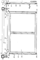
- FIG. 6 shows a clamping device to be used in connection with the tarpaulin frame for fixing the tarpaulin of the sliding roof in the closed state on the side walls of the vehicle.
- This clamping device has, as can be seen from the front view of a side wall section in FIG. 6 and the cross section according to FIG. 7, a rod 9 which runs a little distance in front of and along the side wall 10 and can be rotated about its longitudinal axis by means of holders 11 the side wall is supported.
- This rod 9 carries a plurality of finger-like or cam-like clamping pieces 12, which serve to clamp the tarpaulin 13 against the side wall 10.
- At least one end of the rod 9 is according to FIG. 8 a lever 14 is arranged for rotating the rod.
- This lever 14 is slidably guided in an eyelet 15 which is rigidly attached to the rod 9.
- the lever 14 in the eyelet 15 In its rest position, in which the clamping pieces 12 are in the clamping position, the lever 14 in the eyelet 15 according to FIG. 8 is pushed down and its lower end 14a is supported on the side wall 10 in order to prevent the lever 14 from pivoting unintentionally to prevent in the opening direction of the clamping pieces 12.
- the lever 14 in the eyelet 15 is pulled upwards and can then be swung away from the side wall, whereby the rod 9 is rotated with the clamping pieces 12 so that these clamping pieces are pivoted upwards into their release position.
- a rope 13a or the like is expediently sewn into the lower edge of the tarpaulin 13 in order to prevent the tarpaulin from slipping out from under the closed clamping pieces 12 due to the thickening of the tarpaulin lower edge.
- the closed tarpaulin can be fixed or detached to the side wall with a handle, so that the lengthy threading or unthreading of the cords required in the conventional tying of the tarpaulin is eliminated.
- the pendulum partition 20 consists of a rigid frame 21 made of profiled bars and a partition wall surface 22, which can consist of sheet metal plates or of a sufficiently stable flexible covering of the frame 21.
- the pendulum partition is locked with pins 23 arranged at its lower end in corresponding openings in the load compartment floor bar and suspended at its upper end by means of brackets 24 on a crossbar 25.
- additional guide rails 30 are arranged on the two longitudinal bars, on which the transverse rod 25 carrying the pendulum partition 20 can be moved in the longitudinal direction of the loading space by means of rollers 31.
- the pendulum partition Since the locking pins 23 are rigidly arranged at the lower end of the pendulum partition, the pendulum partition must be raised in an unlocking position for unlocking so that it can swing out for unloading when the loading surface is tilted, and for moving along the guide rails 30 of the two longitudinal bars 3.
- the crossbar 25 is cranked at both ends, the cranked ends 25a forming the bearing journal for the roller 31 in question.
- the cranked end is formed with a key polygon 26, which is accessible at the possible locking points along the length of the loading space through a recess 30a in the guide rail 30 for inserting a key, by means of which the crossbar 25 can be rotated about the longitudinal axis of its cranked longitudinal sections 25a.
- cranks of the crossbar 25 act as eccentric cranks for pivoting up the central portion of the crossbar 25 carrying the pendulum partition 20 into the unlocking position or for pivoting the same into the locking position. These two positions are shown in side view in FIG. 12.
- the crossbar 25 When swiveling up into the unlocking position, the crossbar 25 is rotated up to a stop above the top dead center of the eccentric crank arrangement, so that the pendulum partition hangs stable in its raised position and can be moved comfortably along the guide rails 30.
- a side wall lock 40 is shown, which can be arranged laterally on the hollow stanchions 2 and therefore protrudes with the outside over the closed side wall.
- This side wall lock 40 consists of a bolt 41 fastened to the side wall and two concentric sleeves 42 and 43 which can be rotated relative to one another, of which the inner sleeve 42 is fastened to the stanchion 2 and the outer sleeve 43 is provided with an "actuating lever 44.
- the two 13, sleeves 42 and 43 each have a lateral insertion slot 42a and 43a, through which the bolt 41 can be moved laterally into and out of these sleeves.
- FIG Relative position of the two sleeves 42 and 43 with overlapping slots 42a and 43a represents the opening position of the drop side lock, in which the bolt 41 can be inserted or carried out, while FIG. 14 shows the closed position of the drop side closure with sleeves 42 and 43 rotated relative to one another shows that the bolt 41 is locked within the sleeve assembly.
- the actuating lever 44 arranged on the outer sleeve 43 is also shown, which can be bent around an axis 45.
- This lever has a nose 44a which, when the lever is bent in the closed position of the side wall lock, engages in a corresponding opening 2a in the stanchion and thus secures the lever 44 against an unintentional opening movement.
- the weight of the lever keeps this lever in its bent position by itself.
Landscapes
- Engineering & Computer Science (AREA)
- Mechanical Engineering (AREA)
- Tents Or Canopies (AREA)
- Operating, Guiding And Securing Of Roll- Type Closing Members (AREA)
Abstract
Description
Die Erfindung betrifft ein Schiebeverdeck-Planengestell, insbesondere für Lastkraftwagen und Anhänger, nach dem Oberbegriff des Anspruchs 1.The invention relates to a sliding roof tarpaulin frame, in particular for trucks and trailers, according to the preamble of claim 1.
Schiebeverdecke sind bei Lastkraftwagen und Anhängern wünschenswert, um einerseits ein Beladen von oben zu ermöglichen und andererseits das Ladegut während der Transportfahrt vollständig abzudecken und gegen Witterungseinflüsse zu schützen. Dabei soll das Schiebeverdeck leicht und schnell zu öffnen und zu schließen sein. Im geöffneten Zustand soll die Ladefläche möglichst frei sein. Außerdem soll das Planengestell schnell und leicht abbaubar und wieder aufbaubar sein.Sliding roofs are desirable for trucks and trailers, on the one hand to allow loading from above and on the other hand to completely cover the load during transport and to protect it against the weather. The sliding roof should be easy and quick to open and close. When opened, the loading area should be as free as possible. In addition, the tarpaulin frame should be quick and easy to dismantle and reassemble.
Bei einem aus der DE-PS 30 14 385 bekannten Schiebeverdeck-Planengestell der eingangs genannten Gattung sind die Querspriegel über scherenartig angeordnete und bewegliche Stützstreben auf Rollenwagen abgestützt, die auf den als Führungsschienen ausgebildeten Längsspriegeln verfahrbar sind. Gleichzeitig verhinden die scherenartigen Stützstreben die Querspriegel untereinander derart, daß beim öffnen des Verdecks sich die von den Stützstreben paarweise gebildeten Scheren schließen und die Querspriegel unter gleichzeitigem Anheben zusammengeschoben werden. Zum öffnen und Schließen des bekannten Schiebeverdecks dient ein vom Boden aus bedienbarer Seiltrieb mit einer über Umlenkrollen und eine Seiltrommel geführten Seilschlaufe, die am hintersten Rollenwagen befestigt ist. Eine der Umlenkrollen muß dabei am hinteren Längsspriegelende angeordnet sein, um beim Schließen des Schiebeverdecks den hintersten Rollenwagen bis zum hinteren Längsspriegelende zurückziehen zu können.In a sliding roof tarpaulin frame of the type mentioned at the beginning of DE-PS 30 14 385, the cross brackets are supported by scissor-like and movable support struts on roller carriages which can be moved on the longitudinal brackets designed as guide rails. At the same time, the scissor-like support struts prevent the crossbars from one another in such a way that When the convertible top is opened, the scissors formed in pairs by the support struts close and the crossbars are pushed together while lifting. To open and close the known sliding roof, a cable drive that can be operated from the ground is used with a cable loop that is guided over deflection pulleys and a cable drum and is attached to the rearmost roller carriage. One of the deflection rollers must be arranged on the rear longitudinal end of the bow so that the rearmost roller carriage can be pulled back to the rear longitudinal bow when the sliding roof is closed.
Die über Stützstreben-Scherenanordnungen und Rollenwagen auf den Längsspriegeln verfahrbar abgestützten Querspriegel der bekannten Anordnung bedingen natürlich eine entsprechend aufwendige und kostenträchtige Konstruktion. Außerdem ist das hintere Längsspriegelende als Fixpunkt für die Seilumlenkung des zum Öffnen und Schließen des Schiebeverdecks dienenden Seiltriebs notwendig und trägt ebenso wie die Tatsache, daß die Rollenwagen gegen Abheben gesichert auf den Längsspriegeln geführt und die Querspriegel alle durch die Stützstreben-Scherenanordnungen untereinander und mit den Rollenwagen verbunden sind, dazu bei, daß im Bedarfsfall ein Abbau und Wiederaufbau des Planengestells wenig praktikabel ist und insbesondere von den höchstens zwei Mann Besatzung eines Lastzuges kaum allein durchgeführt werden kann.The crossbars of the known arrangement, which are supported movably supported on the longitudinal bars via support strut scissor assemblies and roller carriages, naturally require a correspondingly complex and costly construction. In addition, the rear longitudinal bow end is necessary as a fixed point for the cable deflection of the cable drive used to open and close the sliding roof and, like the fact that the roller carriages are secured against lifting off on the longitudinal bow and the cross bow all through the support strut scissor arrangements with each other and with the Roller carriages are connected to the fact that, if necessary, dismantling and reconstruction of the tarpaulin frame is not very practical and, in particular, can hardly be carried out by the maximum of two men on a truck.
Der Erfindung liegt demgegenüber die Aufgabe zugrunde, ein Schiebeverdeck-Planengestell der eingangs genannten Gattung dahingehend auszubilden, daß es leicht, von einfacher und kostengünstiger Konstruktion, trotzdem leicht zu öffnen und zu schließen und von einer Lastwagenbesatzung allein ohne Schwierigkeiten auf- und abbaubar ist.The invention is based on the object to design a sliding roof tarpaulin frame of the type mentioned in such a way that it is light, simple and inexpensive construction, yet easy to open and close and can be assembled and dismantled by a truck crew alone without difficulty.
Diese Aufgabe wird bei einem Schiebeverdeck-Planengestell der in Rede stehenden Gattung gemäß der Erfindung durch die im kennzeichnenden Teil des Anspruchs 1 angegebenen Konstruktionsmerkmale gelöst.This object is achieved in a sliding roof tarpaulin frame of the type in question according to the invention by the design features specified in the characterizing part of claim 1.
Zum öffnen des erfindungsgemäßen Schiebeverdecks kann in an sich bekannter Weise ein Seiltrieb Anwendung finden, dessen Seil am hintersten Querspriegel befestigt und auf eine im Bereich des vorderen Endes der Ladefläche angeordnete Seiltrommel aufspulbar ist. Zum öffnen des Schiebeverdecks genügt ein ebenfalls am hintersten Querspriegel befestigtes Zugseil oder dergleichen, mittels welchem das Schiebeverdeck nach hinten in seine Schließstellung gezogen werden kann, ohne daß dazu ein Seiltrieb erforderlich ist. Die einzelnen Querspriegel sind erfindungsgemäß durch flexible Zwischenglieder, nämlich Verbindungsgurte oder ähnliches miteinander verbunden, die sich beim Schließen des Verdecks spannen und dadurch die richtigen gegenseitigen Abstände der Querspriegel sich während des Schließvorgangs automatisch einstellen.To open the sliding roof according to the invention, a cable drive can be used in a manner known per se, the cable of which is attached to the rearmost cross bow and can be wound onto a cable drum arranged in the region of the front end of the loading area. To open the sliding roof, a traction rope or the like, which is also attached to the rearmost crossbar, is sufficient, by means of which the sliding roof can be pulled back into its closed position without the need for a cable drive. According to the invention, the individual cross brackets are connected to one another by flexible intermediate links, namely connecting belts or the like, which tighten when the convertible top is closed, and the correct mutual distances between the cross brackets are automatically set during the closing process.
Die erfindungsgemäße Konstruktion hat den Vorteil eines sehr einfachen konstruktiven Aufbaus, demzufolge auch einer sehr kostengünstigen Herstellbarkeit, und außerdem ist die gesamte Konstruktion gewichtsmäßig leicht und läßt sich jederzeit einfach auseinandernehmen bzw. zusammenbauen, wenn, beispielsweise um den Ladevorgang zu erleichtern, das Planengestell vollständig oder teilweise abgenommen werden soll. Da bei dem erfindungsgemäßen Schiebeverdeck-Planengestell wegen seiner leichten Bauweise kein doppeltwirkender Seiltrieb zum öffnen und-Schließen notwendig ist und dadurch auch ein am hinteren Längsspriegelende angeordneter Seilumlenkungsfixpunkt sowie die übrige komplizierte und gegen Abgleiten des Seils empfindliche Seilumlenkungsmechanik entbehrlich sind, wird das Auf- und Abbauen des Planengestells beträchtlich erleichtert.The construction according to the invention has the advantage of a very simple construction, consequently also a very inexpensive to manufacture, and in addition the entire construction is light in weight and can be easily disassembled or assembled at any time if, for example to facilitate the loading process, the tarpaulin frame is complete or should be partially removed. Since in the sliding roof tarpaulin frame according to the invention, because of its light construction, no double-acting cable drive is necessary to open and close, and therefore a cable deflection fixed point arranged at the rear longitudinal bow end as well as the other complicated cable deflection mechanics that are sensitive to sliding of the cable are unnecessary, assembly and disassembly are unnecessary of the tarpaulin frame considerably easier.
Vorteilhafte Ausgestaltungen der Erfindung sind Gegenstand der Unteransprüche.Advantageous embodiments of the invention are the subject of the dependent claims.
Demgemäß sind die Schiebekörper vorzugsweise als Gleitkörper ausgebildet, die um eine vertikale Achse drehbar mit den Querspriegeln verbunden sind. Dadurch wird ein Verkanten der Schiebekörper mit Bezug auf die Führungsschienen auch dann vermieden, wenn beim öffnen oder Schließen ein einseitiger Zug auf die Querspriegel wirkt, da dann die Schiebekörper stets parallel zur Führungsschiene laufen können, selbst wenn sich die Querspriegel im Verlaufe ihrer Verschiebung etwas schräg stellen sollten.Accordingly, the sliding bodies are preferably designed as sliding bodies which are connected to the transverse brackets so as to be rotatable about a vertical axis. This prevents the sliding bodies from tilting with respect to the guide rails even if a one-sided pull acts on the cross brackets when opening or closing, since then the sliding bodies can always run parallel to the guide rail, even if the cross brackets move somewhat obliquely in the course of their displacement should ask.
Die Längsspriegel sind zweckmäßigerweise als die Schiebekörper aufnehmende Hohlprofil-Führungsschienen ausgebildet. Dadurch sind die Schiebekörper gleichzeitig gegen äußere Einwirkungen geschützt.The longitudinal bars are expediently designed as hollow-profile guide rails that receive the sliding bodies. As a result, the sliding bodies are protected against external influences at the same time.
Die Schiebekörper sind zweckmäßig als längliche Prismenkörper ausgebildet, deren Länge ausreichend groß gewählt ist, um ein Verkanten in den Führungsschienen sicher zu vermeiden. Aber um in der öffnungsstellung des Schiebeverdecks die Querspriegel trotzdem möglichst eng aneinander anliegend zusammenschieben zu können, sind die Schiebekörper vorzugsweise zwar mit über ihre ganze Länge verlaufenden, mit Führungsflächen der Führungsschienen zusammenwirkenden Gleitflächen, jedoch teilweise ineinanderschiebbar gestaltet. Dies läßt sich dadurch realisieren, daß die Schiebekörper an ihren beiden Enden mit zueinander komplementären Querschnittsprofilen ausgebildet sind, bei denen jeweils ein Teil ihres Umfangs durch eine Gleitfläche gebildet ist. Damit lassen sich die Schiebekörper mit ihren Endabschnitten zusammenschieben, obwohl sich mindestens Teile ihrer Gleitflächen über ihre ganze Länge erstrecken. Beispielsweise kann das eine Ende dieses Schiebekörpers gabelartig und das andere Ende dazu komplementär stegartig ausgebildet sein. Auch diagonal versetzte Zapfenprofile oder dergleichen sind möglich.The sliding bodies are expediently designed as elongated prism bodies, the length of which is selected to be sufficiently large to reliably prevent tilting in the guide rails. But in order to be able to push the cross brackets together as closely as possible in the open position of the sliding roof, the sliding bodies are preferably designed with sliding surfaces that extend over their entire length and interact with guide surfaces of the guide rails, but are partially designed such that they can be pushed into one another. This can be achieved in that the sliding bodies are formed at their two ends with mutually complementary cross-sectional profiles, in each of which part of their circumference is formed by a sliding surface. This allows the sliding bodies to be pushed together with their end sections, although at least parts of their sliding surfaces extend over their entire length. For example one end of this sliding body is fork-like and the other end is complementary web-like. Also diagonally offset Za p fenprofile or the like are possible.
Um mit geringstmöglichem Wartungsaufwand hinsichtlich Schmierung usw. auskommen zu können, sind die Gleitkörper vorzugsweise aus reibungsarmem Kunststoff hergestellt.In order to be able to make do with the least possible maintenance with regard to lubrication etc., the sliding bodies are preferably made of low-friction plastic.
Die Längsspriegel des Planengestells können geteilt ausgebildet und ihre Längenabschnitte mittels einer Schnellkupplung trennbar bzw. verbindbar sein, so daß auch ein teilweiser Abbau des Planengestells im Bedarfsfall schnell und einfach möglich ist.The longitudinal bars of the tarpaulin frame can be divided and their length sections can be separated or connected by means of a quick coupling, so that a partial dismantling of the tarpaulin frame is also possible quickly and easily if necessary.
Um die lichte Höhe des Laderaums unter dem Schiebeverdeck den Erfordernissen der jeweiligen Ladung anpassen zu können, ist auch eine Höhenverstellung des Schiebeverdecks wünschenswert. Dazu sind die vertikalen Stützen vorteilhafterweise im hohlen Rungen aus- und einschiebbar geführt und in bestimmten Vertikalpositionen arretierbar. Diese Art der Höhenverstellbarkeit eines Planengestells ist an sich bereits bekannt (DE-OS 31 83 338).In order to be able to adapt the clear height of the loading space under the sliding roof to the requirements of the respective load, it is also desirable to adjust the height of the sliding roof. For this purpose, the vertical supports are advantageously guided in and out of the hollow stanchions and can be locked in certain vertical positions. This type of height adjustability of a tarpaulin frame is already known per se (DE-OS 31 83 338).
Die hohle Ausbildung der Rungen für die Höhenver- . stellbarkeit des Planengestells erfordert natürlich eine gewisse Dicke der Rungen. Damit werden aber die herkömmlichen, außen auf die Rungen aufgesetzten Bordwandverschlüsse zum Problem, denn einerseits darf die Außenbreite des Fahrzeugs den gesetzlichen Höchstwert von 2,50 m nicht überschreiten, andererseits soll das Richtmaß zwischen den Rungen beiderseits der Ladefläche nicht kleiner als 2,42 m sein, um eine bestimmte Anzahl genormter Paletten zwischen den Lichtraumbegrenzungen beiderseits der Ladefläche unterbringen zu können. Damit verbleibt für die maxiamle Rungendicke einschließlich der Bordwandverschlüsse nur noch ein Maß von etwa 4 cm. Die Erfindung schlägt deshalb seitlich an den Rungen anbringungsfähige Bordwandverschlüsse vor, die aus einem Bolzen und zwei konzentrischen, relativ zueinander drehbaren Hülsen besteht, wobei die beiden Hülsen jeweils mit einem seitlichen Einführungsschlitz zum Einführen des Bolzens versehen sind. Dabei ist eine der beiden Hülsen mit einem Betätigungsorgan zum Drehen versehen, während von den beiden anderen Teilen das eine an der Bordwand und das andere an der hohlen Runge befestigt ist. Wird nun die eine Hülse mittels des Betätigungsorgans so gedreht, daß sich die seitlichen Einführungsschlitze beider Hülsen decken, kann der Bolzen ein- oder ausgeführt werden, und wird die eine Hülse so gedreht, daß die Einführungsschlitze beider Hülsen sich nicht mehr überdecken, bis der eingeführte Bolzen in der Hülsenanordnung verriegelt. Zweckmäßigerweise hat der Bolzen einen im Durchmesser verdickten Kopf, dessen rückwärtige Stirnfläche mit einer entsprechenden axialen Schulter der inneren Hülse zusammenwirkt, um den Bolzen auch gegen axialen Herausgleiten aus der Hülsenanordnung zu sichern. Das Betätigungsorgan kann ein Hebel sein, der in der Schließstellung des Bordwandverschlusses abknickbar ist und eine Nase aufweist, die bei abgeknicktem Hebel in eine entsprechende öffnung der Runge eingreift, um den Hebel in der Schließstellung der Hülsenanordnung zu sichern.The hollow formation of the stanchions for height adjustment. Adjustment of the tarpaulin frame naturally requires a certain thickness of the stanchions. However, this means that the conventional dropside locks placed on the stanchions on the outside become a problem, because on the one hand the outside width of the vehicle must not exceed the legal maximum of 2.50 m, on the other hand the standard dimension between the stanchions on both sides of the loading area should not be less than 2.42 m be able to accommodate a certain number of standardized pallets between the clearances on both sides of the loading area. That leaves for the maxiamle stanchion thickness including the drop side locks is only about 4 cm. The invention therefore proposes sideways to be attached to the stanchions side wall closures, which consists of a bolt and two concentric, rotatable sleeves, the two sleeves are each provided with a lateral insertion slot for inserting the bolt. One of the two sleeves is provided with an actuator for turning, while one of the other two parts is attached to the side wall and the other to the hollow stanchion. If one sleeve is now rotated by means of the actuating member in such a way that the lateral insertion slots of both sleeves overlap, the bolt can be inserted or carried out, and the one sleeve is rotated so that the insertion slots of both sleeves no longer overlap until the inserted one Bolt locked in the sleeve arrangement. The bolt expediently has a head which is thickened in diameter, the rear end face of which cooperates with a corresponding axial shoulder of the inner sleeve in order to secure the bolt against axial sliding out of the sleeve arrangement. The actuating member can be a lever that can be bent in the closed position of the dropside lock and has a nose that engages in a corresponding opening of the stanchion when the lever is bent in order to secure the lever in the closed position of the sleeve arrangement.
Die Befestigung von Abdeckplanen an den Bordwänden erfolgt bekanntermaßen üblicherweise mit Hilfe von im Bereich der Planenkante angeordneten ösen und an der Bordwand befestigten Schnurösen, auf welche die Plane mit ihren Ösen aufgesteckt und anschließend eine Schnur hindurchgezogen wird. Diese Art der Planenfixierung ist allerdings bei einem Schiebeverdeck hinderlich, da die Plane auch bei gelöster Schnur dazu neigt, mit ihren Ösen auf den Schnurösen der Bordwände hängenzubleiben und dadurch das öffnen und Schließen zu erschweren. Zur Behebung dieses Problems ist dem erfindungsgemäßen Planengestell vorzugsweise eine Klemmvorrichtung zur Fixierung der Plane an den Bordwänden zugeordnet, die aus einer mit Abstand entlang der Bordwand verlaufend an dieser gehalterten drehbaren Stange und aus damit starr verbundenen finger- oder nockenartigen Klemmstücken besteht, die durch Drehen der Stange zur Bordwand hin bzw. von dieser wegschwenkbar sind. Hiermit läßt sich das Fixieren bzw. Lösen der Plane auch bedeutend schneller bewerkstelligen als mit der herkömmlichen Verschnürung.As is known, the fastening of tarpaulins to the side walls usually takes place with the aid of eyelets arranged in the area of the edge of the tarpaulin and fastened to the side wall, onto which the tarpaulin is attached with its eyelets and then a cord is pulled through. This type of tarpaulin fixation is however, a hindrance for a sliding roof, since the tarpaulin tends to get stuck with the eyelets on the cord eyelets of the side walls and thus make opening and closing difficult. To remedy this problem, the tarpaulin frame according to the invention is preferably assigned a clamping device for fixing the tarpaulin to the side walls, which consists of a rotatable rod running at a distance along the side wall and of finger-like or cam-like clamping pieces rigidly connected therewith, which by rotating the Rod can be pivoted towards the side wall or away from it. This also allows the tarpaulin to be fixed or loosened significantly faster than with conventional lacing.
Um auf einer mit einem Schiebeverdeck abgedeckten Ladefläche mehrere Arten von Schüttgütern getrennt voneinander transportieren zu können, ist es bereits bekannt, im Zusammenhang mit Planengestellen Pendeltrennwände vorzusehen, die an einer bestimmten Stelle der Ladefläche, beispielsweise im Bereich der Mittelrungen, einsetzbar und verriegelbar sind, um die Ladefläche in verschiedene Abschnitte zur Aufnahme der verschiedenen Schüttgüter zu unterteilen. Um hier die Einsatzmöglichkeiten im Hinblick auf eine variable Unterteilung der Laderaumfläche zu verbessern, sind gemäß einer Weiterbildung der Erfindung die Längsspriegel mit Längsführungen zum Verschieben solcher Pendeltrennwände in Längsrichtung der Ladefläche versehen. Auf diesem Längsführungen der Längsspriegel können die Pendeltrennwände auf Rollen verfahrbar sein. Damit ist eine variable Laderaumunterteilung möglich, wobei lediglich in gewissen kurzen Abständen Arretierungsmöglichkeiten für die Pendeltrennwände vorgesehen sein müssen.In order to be able to transport several types of bulk goods separately from one another on a loading area covered with a sliding roof, it is already known in connection with tarpaulin frames to provide pendulum partition walls which can be used and locked at a specific point on the loading area, for example in the area of the central stanchions divide the loading area into different sections to accommodate the various bulk goods. In order to improve the possible uses with regard to a variable subdivision of the loading space area, according to a development of the invention, the longitudinal bow is provided with longitudinal guides for moving such pendulum partition walls in the longitudinal direction of the loading area. The pendulum partition walls can be moved on rollers on this longitudinal guide of the longitudinal bow. This allows a variable load compartment subdivision, with locking options for the pendulum partitions only having to be provided at certain short intervals.
Ublicherweise erfolgt die Verriegelung der Pendeltrennwände mit Hilfe von an ihren Unterkanten angeordneten, in entsprechende öffnungen des Laderaumbodens eingreifenden Zapfen. Um bei starrer Ausbildung dieser Zapfen die Pendeltrennwände in eine Entriegelungsstellung anheben zu können, in welcher sie entlang der Längsspriegel verfahrbar sind bzw. zum Entladen auspendeln können, erfolgt die Aufhängung der Pendeltrennwände an den entlang den Längsspriegeln verlaufenden Führungen vorzugsweise über Exzenterkurbelmechanismen, mittels derer die Pendeltrennwände wahlweise in eine Entriegelungsstellung anhebbar bzw. eine Verriegelungsstellung absenkbar sind. Dabei kann die Rollenachse als Exzenterkurbelwelle dienen und an ihrem äußeren Stirnende mittels eines auf- oder einsteckbaren Schlüssels drehbar sein, während ein daran angeordneter Exzenterkurbelzapfen als Scharnierzapfen für die Aufhängung der Pendeltrennwände ausgebildet ist und durch Drehung der Exzenterkurbelwelle bis in eine über dem oberen Totpunkt liegende Anschlagstellung hinaus schwekbar ist, so daß die Pendeltrennwand sich in der angehobenen Stellung in einer stabilen, leicht verfahrbaren Position befindet.Usually, the pendulum partitions are locked with the aid of pins arranged on their lower edges and engaging in corresponding openings in the load compartment floor. In order to be able to lift the pendulum partitions into an unlocked position in the rigid construction of these pins, in which they can be moved along the longitudinal bars or can swing out for unloading, the pendulum partitions are preferably suspended on the guides running along the longitudinal bars via eccentric crank mechanisms by means of which the pendulum partitions can optionally be raised to an unlocking position or a locking position can be lowered. The roller axis can serve as an eccentric crankshaft and can be rotated at its outer end by means of an insertable or insertable key, while an eccentric crank pin arranged thereon is designed as a hinge pin for the suspension of the pendulum partition walls and by rotating the eccentric crankshaft to a stop position above the top dead center is also pivotable so that the pendulum partition is in the raised position in a stable, easily movable position.
Ein Ausführungsbeispiel der Erfindung wird nachstehend unter Bezugnahme auf die anliegenden Zeichnungen mehr im einzelnen beschrieben. In den Zeichnungen zeigen:
- Fig. 1 ein Schiebeverdeck-Planengestell nach der Erfindung für einen Lastwagenanhänger in Seitenansicht,
- Fig. 2 das Planengestell in Draufsicht,
- Fig. 3 einen Querschnitt eines Längsspriegels mit einem darin geführten Gleitkörper und dessen Verbindung mit einem Querspriegel,
- die Fig. 4a und 4b eine erste Ausführungsvariante eines Gleitkörpers,
- die Fig. 5a und 5b eine zweite Ausführungsvariante eines Gleitkörpers,
- Fig. 6 eine Klemmvorrichtung zur Fixierung der Plane an der Bordwand in Frontansicht,
- die Fig. 7 und 8 Querschnitte in den Ebenen VII-VII bzw. VIII-VIII in Fig. 6,
- die Fig. 9 und 10 in Frontansicht bzw. Seiten ansicht eine Pendeltrennwand zur Querunterteilung des Laderaums,
- die Fig. 11 und 12 Einzelheiten der Pendeltrennwandaufhängung in Front- und Seitenansicht,
- die Fig. 13 und 14 jeweils im Querschnitt einen Bordwandverschluß in geöffneter bzw. geschlossener Stellung, und
- Fig. 15 den Bordwandverschluß mit Betätigungshebel in Seitenansicht.
- 1 is a side view of a sliding tarpaulin frame according to the invention for a truck trailer,
- 2 the tarpaulin frame in plan view,
- Fig. 3 shows a cross section of a longitudinal bow with a ge therein led sliding body and its connection with a cross bow,
- 4a and 4b a first embodiment of a sliding body,
- 5a and 5b, a second embodiment of a sliding body,
- 6 shows a clamping device for fixing the tarpaulin to the side wall in a front view,
- 7 and 8 cross sections in the levels VII-VII and VIII-VIII in Fig. 6,
- 9 and 10 in front view and side view of a pendulum partition for the transverse division of the cargo space,
- 11 and 12 details of the pendulum partition suspension in front and side view,
- 13 and 14 each in cross section a side panel lock in the open or closed position, and
- Fig. 15 the side panel lock with operating lever in side view.
Die Fig. 1 und 2 zeigen in Seitenansicht und Draufsicht ein Schiebeverdeck-Planengestell nach der Erfindung auf einen Lastwagenanhänger.1 and 2 show a side view and top view of a sliding tarpaulin frame according to the invention on a truck trailer.
Das Planengestell besteht aus beiderseits der Ladefläche angeordneten vertikalen Stützen 1, die zwecks Höhenverstellbarkeit des Planengestells in hohlen Rungen 2 aus- und einschiebbar geführt und in bestimmten Höhenpositionen arretierbar sind, weiter aus zwei von den vertikalen Stützen 1 getragenen Längsspriegeln 3 und einer Anzahl von in der Draufsicht nach Fig. 2 sichtbaren, zwischen den beiden Längsspriegeln 3 verlaufenden Querspriegeln 4.The tarpaulin frame consists of vertical supports 1 arranged on both sides of the loading area, which can be extended and retracted in
Wie aus Fig. 3 hervorgeht, sind die beiden Längsspriegel 3 jeweils als Hohlprofil-Führungsschienen ausgebildet, deren Querschnittsprofil gemäß Fig. 3 beispielsweise etwa quadratisch oder rechteckig, aber auch in anderer Weise polygonal oder kreisrund sein kann. In diesen Führungsschienen sind Gleitkörper 5 mit entsprechendem Querschnittsprofil verschiebbar geführt, die mit den Enden der Querspriegel 4 verbunden sind. Die Verbindung mit dem betreffenden Querspriegelende erfolgt beispielsweise mittels einer an dem Querspriegelende befestigten Lasche 5 und einem Bolzen 6, der durch eine entsprechende Bohrung des Gleitkörpers 5 hindurchverläuft und mit seinen unterem Ende an der Lasche 5 befestigt ist. Der Bolzen 6 sitzt dabei drehbar in der Bohrung des Gleitkörpers 5 und bildet einen Scharnierbolzen mit vertikaler Achse, um welchen der Gleitkörper 5 drehbar ist. Auf diese Weise wird ein Verkanten des Gleitstückes 5 in der Führungsschiene vermieden, wenn der betreffende Querspriegel sich aus seiner exakt quer verlaufenden Position etwas schräg stellen sollte.As can be seen from FIG. 3, the two
Da die Querspriegel 4 alle in der eben beschriebenen Weise über Gleitkörper 5 in den als Führungsschienen ausgebildeten Längsspriegeln 3 verschiebbar geführt sind, lassen sich die Querspriegel zum öffnen des Verdecks in Richtung zum vorderen Ende des Planengestells zusammenschieben. Dazu kann ein Seiltrieb mit einer im Bodenbereich des vorderen Laderaumendes angeordneten, mit Kurbel versehenen Seiltrommel 7 Anwendung finden, die in Fig. 1 dargestellt ist, deren Seil am hintersten Querspriegel 4a (siehe Fig. 2) befestigt ist. Dieser Seiltrieb wirkt nur in öffnungsrichtung, ist dafür aber äußerst einfach ausgebildet. Zum Schließen des Verdeckes genügt ein ebenfalls am hintersten Querspriegel 4a befestigter Zuggurt (nicht dargestellt), mit welchem der Fahrer das Verdeck nach hinten in seine geschlossene Stellung ziehen kann. Die einzelnen Querspriegeln sind durch Verbindungsgurte 41 oder dergleichen miteinander verbunden, so daß sich beim Schließen des Verdecks die richtigen gegenseitigen Abstände der Querspriegel voneinander durch Straffen dieser Verbindungsgurte automatisch einstellen.Since the cross brackets 4 are all slidably guided in the manner just described via sliding
Die Fig. 4a und 4b sowie 5a und 5b zeigen jeweils in Seiten- und Stirnansicht zwei zweckmäßige Ausführungsvarianten der Gleitkörper 5. Einerseits sollen diese Gleitkörper 5, um ein Verkanten in den sie führenden Führungsschienen zu vermeiden und dadurch ein leichtes Verschieben der Querspriegel zu ermöglichen, eine ausreichende Führungslänge haben, andererseits sollen aber die Querspriegel zum möglichst weitgehenden öffnen des Verdecks möglichst eng zusammenschiebbar sein. Die beiden dargestellten Ausführungsmöglichkeiten von Gleitkörpern 5 tragen diesen beiden Anforderungen Rechnung, indem sie teilweise zusammenschiebbar gestaltet sind, ohne dabei jedoch ihre Führungslänge zu verringern.4a and 4b as well as 5a and 5b each show a side and front view of two expedient design variants of the sliding
Bei der Ausführungsvariante nach den Fig. 4a und 4b ist das eine Ende 5a des Gleitkörpers 5 gegabelt und das andere Ende 5b dieses Gleitkörpers dazu komplementär stegartig ausgebildet, so daß sich die aufeinanderfolgenden Gleitstücke teilweise ineinanderschieben lassen. Während die obere Gleitfläche 51 und die untere Gleitfläche 52 (Fig. 4a) dieses Gleitkörpers sich nur über etwas mehr als die Hälfte der Gleitkörperlänge erstrecken, entspricht die wirksame Länge der beiden seitlichen Gleitflächen 53, die einem seitlichen Verkanten des Gleitkörpers entgegenwirken, über die volle Gleitkörperlänge und ergeben dadurch eine optimale Führung.In the embodiment variant according to FIGS. 4a and 4b, one
Bei der Ausführungsvariante nach den Fig. 5a und 5b ist die Gestaltung der zueinander komplementären Querschnittsprofile der beiden Gleitkörperenden 5a und 5b dahingehend abgewandelt, daß, wie aus der Stirnansicht nach Fig. 5b hervorgeht, diese Endabschnitte jeweils durch zwei jeweils einem Viertel des Vollquerschnitts des Gleitkörpers entsprechende Zapfen gebildet sind, die an einem Endabschnitt 5a auf der einen Gleitkörperdiagonalen und beim anderen Endabschnitt 5b auf der anderen Gleitkörperdiagonalen liegen, so daß die aufeinanderfolgenden Gleitkörper wiederum teilweise zusammenschiebbar sind. Dabei hat die letztere Ausführungsform den Vorzug, daß sowohl die obere und untere als auch die beiden seitlichen Gleitflächen des Gleitkörpers 5 eine wirksame Länge haben, die der Gesamtlänge des Gleitkörpers entspricht. Allerdings ist die Steifigkeit der ersteren Ausführungsvariante nach den Fig. 4a und 4b mit Bezug auf die Seitenführung größer als die Steifigkeit der letzteren Ausführungsvariante nach den Fig. 5a und 5b.5a and 5b, the design of the mutually complementary cross-sectional profiles of the two sliding body ends 5a and 5b has been modified such that, as can be seen from the front view according to FIG. 5b, these end sections each by two-fourths of the full cross-section of the sliding body Corresponding pins are formed, which are located on one
In jedem Fall sind die Gleitkörper vorzugsweise aus einem reibungsarmen Kunststoff wie beispielsweise PVC oder Polyamid hergestellt, wodurch einerseits eine leichte Verschiebbarkeit der Qurspriegel bei minimalen Aufwand für Schmierung und anderereits auch eine hohe Verschleißfestigkeit der Konstruktion erreicht wird.In any case, the sliding bodies are preferably made of a low-friction plastic such as PVC or polyamide, which on the one hand allows the cross bend to be moved easily with minimal effort for lubrication and, on the other hand, the construction is highly resistant to wear.
Selbstverständlich können anstelle der Gleitkörper auch mittels Rollen in bzw. an den Längsspriegeln geführte Schiebekörper Anwendung finden, wobei der damit erreichte Vorteil einer noch geringeren Reibung beim Verschieben der Querspriegel allerdings durch einen wesentlich höheren konstruktiven Aufwand erkauft werden muß.Of course, instead of the sliding bodies, sliding bodies guided in or on the longitudinal bars can also be used, the advantage achieved thereby of an even lower friction when moving the transverse bars, however, having to be bought through a considerably higher design effort.
Wie aus den Fig. 1 und 2 außerdem hervorgeht, sind die beiden Längsspriegel 3 zweckmäßigerweise geteilt ausgebildet, wobei die Länge des vorderen Teils 3a der Querspriegel der Länge des zusammengeschobenen Verdecks entspricht, also sämtliche Querspriegel im zusammengeschobenen Zustand aufnehmen, während der hintere Teil 3b der Längsspriegel sich über die restliche Länge erstreckt. Die beiden Längsspriegelteile 3a und 3b sind jeweils mittels einer Schnellkupplung 8 beliebiger Bauart miteinander verbunden. Dadurch ist es möglich, bei geöffnetem Verdeck den gesamten hinteren Teil des Planengestells, bestehend aus den hinteren Längsspriegelteilen 3b und den zugehörigen Stützen 1, schnell und einfach abzubauen, beispielsweise um eine Beladung oder Entladung zu erleichtern.As can also be seen from FIGS. 1 and 2, the two
Die Fig. 6, 7 und 8 zeigen eine in Verbindung mit dem Planengestell zu verwendende Klemmvorrichtung zur Fixierung der Plane des Schiebeverdecks in geschlossenem Zustand an den Bordwänden des Fahrzeugs. Diese Klemmvorrichtung weist, wie aus der Frontansicht eines Bordwandausschnitts in Fig. 6 und dem Querschnitt nach Fig. 7 ersichtlich ist, eine Stange 9 auf, die mit etwas Abstand vorderhalb der Bordwand 10 und entlang derselben verläuft und mittels Haltern 11 um ihre Längsachse drehbar an der Bordwand gehaltert ist. Diese Stange 9 trägt eine Mehrzahl von finger- oder nockenartigen Klemmstücken 12, die dazu dienen, die Plane 13 gegen die Bordwand 10 zu klemmen. An mindestens einem Ende der Stange 9 ist gemäß Fig. 8 ein Hebel 14 zum Drehen der Stange angeordnet. Dieser Hebel 14 ist in einer Öse 15, die starr an der Stange 9 befestigt ist, verschiebbar geführt. In seiner Ruhestellung, in welcher die Klemmstücke 12 sich in der Klemmstellung befinden, ist der Hebel 14 in der Öse 15 gemäß Fig. 8 nach unten geschoben und sein unteres Ende 14a stützt sich an der Bordwand 10 ab, um ein ungewolltes Schwenken des Hebels 14 in öffnungsrichtung der Klemmstücke 12 zu verhindern. Zum Lösen der Klemmstücke 12 wird der Hebel 14 in der Öse 15 nach oben gezogen und läßt sich dann von der Bordwand weg ausschwenken, wodurch die Stange 9 mit den Klemmstücken 12 so gedreht wird, daß diese Klemmstücke nach oben in ihre Lösestellung geschwenkt werden. In die Unterkante der Plane 13 ist zweckmäßigerweise ein Seil 13a oder dergleichen eingenäht, um durch die so geschaffene Verdickung der Planenunterkante ein Herausrutschen der Plane unter den geschlossenen Klemmstücken 12 zu vermeiden.6, 7 and 8 show a clamping device to be used in connection with the tarpaulin frame for fixing the tarpaulin of the sliding roof in the closed state on the side walls of the vehicle. This clamping device has, as can be seen from the front view of a side wall section in FIG. 6 and the cross section according to FIG. 7, a rod 9 which runs a little distance in front of and along the
Mit der eben beschriebenen Klemmvorrichtung läßt sich die geschlossene Plane mit einem Handgriff an der Bordwand fixieren oder lösen, so daß das bei der herkömmlichen Verschnürung der Plane notwendige langwierige Ein- oder Ausfädeln der Schnüre entfällt.With the clamping device just described, the closed tarpaulin can be fixed or detached to the side wall with a handle, so that the lengthy threading or unthreading of the cords required in the conventional tying of the tarpaulin is eliminated.
Die Fig. 9 und 10 zeigen in Front- und Seitenansicht eine Pendeltrennwand, die zur Querunterteilung des Laderaums in Verbindung mit den erfindungsgemäßen Planengestell verwendbar ist. Die Pendeltrennwand 20 besteht aus einem steifen Rahmen 21 aus Profilstäben und einer Trennwandfläche 22, die aus Blechplatten oder auch aus einer ausreichend stabilen flexiblen Bespannung des Rahmens 21 bestehen kann. Die Pendeltrennwand ist mit an ihrem unteren Ende angeordneten Zapfen 23 in entsprechenden Öffnungen des Laderaumbodens arretierbar und an ihrem oberen Ende mittels Laschen 24 pendelfähig an einer Querstange 25 aufgehängt.9 and 10 show in front and side view a pendulum partition which can be used for transverse division of the cargo space in connection with the tarpaulin frame according to the invention. The
Wie aus Fig. 9, besonders aber aus der größeren Darstellung nach Fig. 11 hervorgeht, sind an den beiden Längsspriegeln zusätzliche Führungsschienen 30 angeordnet, auf denen die, die Pendeltrennwand 20 tragende Querstange 25 mittels Rollen 31 in Längsrichtung des Laderaumes verfahrbar ist.As can be seen from FIG. 9, but particularly from the larger representation according to FIG. 11,
Da die Arretierungszapfen 23 am unteren Pendeltrennwandende starr angeordnet sind, muß die Pendeltrennwand zum Entriegeln, damit sie zum Entladen beim Kippen der Ladefläche auspendeln kann, sowie zum Verfahren entlang der Führungsschienen 30 der beiden Längsspriegel 3 in eine Entriegelungsstellung angehoben werden. Dazu ist die Querstange 25 an ihren beiden Enden gekröpft, wobei die gekröpften Enden 25a den Lagerzapfen für die betreffende Rolle 31 bilden. Außerdem ist das gekröpfte Ende mit einem Schlüsselvielkant 26 ausgebildet, der an den möglichen Arretierungsstellen entlang der Laderaumlänge durch eine Aussparung 30a der Führungsschiene 30 hindurch zum Aufstecken eines Schlüssels zugänglich ist, mittels welchem die Querstange 25 um die Längsachse ihrer gekröpften Längsabschnitte 25a drehbar ist. Die Kröpfungen der Querstange 25 wirken dabei als Exzenterkurbeln zum Hochschwenken des die Pendeltrennwand 20 tragenden Mittelabschnitts der Querstange 25 in die Entriegelungsstellung bzw. zum Abschwenken derselben in die Veriegelungsstellung. Diese beiden Stellungen sind in Fig. 12 in der Seitenansicht dargestellt. Beim Hochschwenken in die Entriegelungsstellung wird die Querstange 25 bis über den oberen Totpunkt der Exzenterkurbelanordnung hinaus gegen einen Anschlag gedreht, so daß die Pendeltrennwand stabil in ihrer angehobenen Stellung hängt und bequem entlang der Führungsschienen 30 verfahrbar ist.Since the locking pins 23 are rigidly arranged at the lower end of the pendulum partition, the pendulum partition must be raised in an unlocking position for unlocking so that it can swing out for unloading when the loading surface is tilted, and for moving along the guide rails 30 of the two
In den Fig. 13 bis 15 ist ein Bordwandverschluß 40 dargestellt, der seitlich an den hohlen Rungen 2 angeordnet werden kann und daher mit nach Außen über die geschlossene Bordwand übersteht.13 to 15, a
Dieser Bordwandverschluß 40 besteht aus einem an der Bordwand befestigten Bolzen 41 und zwei konzentrischen, relativ zueinander drehbaren Hülsen 42 und 43, von denen die innere Hülse 42 an der Runge 2 befestigt und die äußere Hülse 43 mit einem "Betätigungshebel 44 versehen ist. Die beiden Hülsen 42 und 43 weisen, wie aus dem Querschnitt nach Fig. 13 hervorgeht, jeweils einen seitlichen Einführungsschlitz 42a bzw. 43a auf, durch welchen der Bolzen 41 seitlich in diese Hülsen hinein bzw. aus ihnen heraus bewegbar ist. Die in Fig. 13 dargestellte Relativstellung der beiden Hülsen 42 und 43 mit sich deckenden Schlitzen 42a und 43a stellt die öffnungsstellung des Bordwandverschlußes dar, in welcher der Bolzen 41 ein- bzw. ausführbar ist, während Fig. 14 die Schließstellung des Bordwandverschlusses mit relativ zueinander so gedrehten Hülsen 42 und 43 zeigt, daß der Bolzen 41 innerhalb der Hülsenanordnung arretiert ist.This
In der Seitenansicht nach Fig. 15 ist auch der an der äußeren Hülse 43 angeordnete Betätigungshebel 44 dargestellt, der um eine Achse 45 abknickbar ist. Dieser Hebel hat eine Nase 44a, die, wenn der Hebel in der Schließstellung des Bordwandverschlusses abgeknickt ist, in eine entsprechende öffnung 2a der Runge eingreift und damit dem Hebel 44 gegen eine unbeabsichtigte öffnungsbewegung sichert. Das Gewicht des Hebels hält dabei diesen Hebel von selbst in seiner abgeknickten Stellung.In the side view according to FIG. 15, the actuating lever 44 arranged on the
Claims (15)
Applications Claiming Priority (2)
| Application Number | Priority Date | Filing Date | Title |
|---|---|---|---|
| DE3425016 | 1984-07-06 | ||
| DE19843425016 DE3425016A1 (en) | 1984-07-06 | 1984-07-06 | SLIDING COVER TILT FRAME |
Publications (2)
| Publication Number | Publication Date |
|---|---|
| EP0168002A2 true EP0168002A2 (en) | 1986-01-15 |
| EP0168002A3 EP0168002A3 (en) | 1986-10-08 |
Family
ID=6240054
Family Applications (1)
| Application Number | Title | Priority Date | Filing Date |
|---|---|---|---|
| EP85108361A Withdrawn EP0168002A3 (en) | 1984-07-06 | 1985-07-05 | Sliding arches for a tarpaulin |
Country Status (2)
| Country | Link |
|---|---|
| EP (1) | EP0168002A3 (en) |
| DE (2) | DE8420338U1 (en) |
Cited By (2)
| Publication number | Priority date | Publication date | Assignee | Title |
|---|---|---|---|---|
| EP0495664A1 (en) * | 1991-01-16 | 1992-07-22 | Christian Seaton Robinson | Vehicle with raisable/lowerable roof |
| EP0925975A2 (en) * | 1997-12-19 | 1999-06-30 | Maschinenfabrik Bernard Krone GmbH | Body structure for commercial vehicle |
Families Citing this family (2)
| Publication number | Priority date | Publication date | Assignee | Title |
|---|---|---|---|---|
| DE3812489C1 (en) * | 1988-04-15 | 1989-11-02 | Gustav Scherrieble Kraftwagenspedition, 7300 Esslingen, De | Lorry having stakes |
| DE4137549C2 (en) * | 1991-11-12 | 1993-11-04 | Christian Koch | CANVAS RACK |
Citations (9)
| Publication number | Priority date | Publication date | Assignee | Title |
|---|---|---|---|---|
| US2469958A (en) * | 1946-01-18 | 1949-05-10 | Roy H Fowler | Motor vehicle cover |
| US2559310A (en) * | 1949-02-02 | 1951-07-03 | Pittsburgh Steel Products Comp | Collapsible cover for vehicles |
| DE1430628A1 (en) * | 1964-07-09 | 1968-11-14 | Blomberg Goete Einar Erling | Slidable roof for transport vehicles, wagons, ships, etc. |
| FR1565186A (en) * | 1967-06-20 | 1969-04-25 | ||
| FR94049E (en) * | 1967-10-25 | 1969-06-20 | Henri Mottez | Device for the quick unloading and unloading of a truck or similar. |
| DE1505367A1 (en) * | 1964-02-28 | 1969-10-09 | Forss Brdr Ab | Equipment on trucks with a cover that can be extended over the platform |
| CA895191A (en) * | 1971-04-09 | 1972-03-14 | Michel Walter | Tarpaulin cover and mounting frame for open truck bodies |
| US3820840A (en) * | 1973-08-01 | 1974-06-28 | J Forsberg | Truck body cover |
| GB2074511A (en) * | 1980-04-15 | 1981-11-04 | Scharwaechter Gmbh Co Kg | A retractable cover for a goods vehicle |
Family Cites Families (1)
| Publication number | Priority date | Publication date | Assignee | Title |
|---|---|---|---|---|
| GB1162181A (en) * | 1966-04-28 | 1969-08-20 | Lars Boerje Svante Herou | Superstructure for Load Carrying Vehicles |
-
1984
- 1984-07-06 DE DE19848420338 patent/DE8420338U1/en not_active Expired
- 1984-07-06 DE DE19843425016 patent/DE3425016A1/en active Granted
-
1985
- 1985-07-05 EP EP85108361A patent/EP0168002A3/en not_active Withdrawn
Patent Citations (9)
| Publication number | Priority date | Publication date | Assignee | Title |
|---|---|---|---|---|
| US2469958A (en) * | 1946-01-18 | 1949-05-10 | Roy H Fowler | Motor vehicle cover |
| US2559310A (en) * | 1949-02-02 | 1951-07-03 | Pittsburgh Steel Products Comp | Collapsible cover for vehicles |
| DE1505367A1 (en) * | 1964-02-28 | 1969-10-09 | Forss Brdr Ab | Equipment on trucks with a cover that can be extended over the platform |
| DE1430628A1 (en) * | 1964-07-09 | 1968-11-14 | Blomberg Goete Einar Erling | Slidable roof for transport vehicles, wagons, ships, etc. |
| FR1565186A (en) * | 1967-06-20 | 1969-04-25 | ||
| FR94049E (en) * | 1967-10-25 | 1969-06-20 | Henri Mottez | Device for the quick unloading and unloading of a truck or similar. |
| CA895191A (en) * | 1971-04-09 | 1972-03-14 | Michel Walter | Tarpaulin cover and mounting frame for open truck bodies |
| US3820840A (en) * | 1973-08-01 | 1974-06-28 | J Forsberg | Truck body cover |
| GB2074511A (en) * | 1980-04-15 | 1981-11-04 | Scharwaechter Gmbh Co Kg | A retractable cover for a goods vehicle |
Cited By (3)
| Publication number | Priority date | Publication date | Assignee | Title |
|---|---|---|---|---|
| EP0495664A1 (en) * | 1991-01-16 | 1992-07-22 | Christian Seaton Robinson | Vehicle with raisable/lowerable roof |
| EP0925975A2 (en) * | 1997-12-19 | 1999-06-30 | Maschinenfabrik Bernard Krone GmbH | Body structure for commercial vehicle |
| EP0925975A3 (en) * | 1997-12-19 | 2000-10-11 | Fahrzeugwerk Bernard Krone GmbH | Body structure for commercial vehicle |
Also Published As
| Publication number | Publication date |
|---|---|
| DE8420338U1 (en) | 1986-01-30 |
| DE3425016C2 (en) | 1988-03-03 |
| EP0168002A3 (en) | 1986-10-08 |
| DE3425016A1 (en) | 1986-01-16 |
Similar Documents
| Publication | Publication Date | Title |
|---|---|---|
| DE112006001492B4 (en) | Side member profile and roof frame for tarpaulin construction | |
| DE1804929A1 (en) | Freight container | |
| DE19756865B4 (en) | Commercial vehicle structure | |
| WO2002092370A2 (en) | Vehicle structure | |
| DE3014385A1 (en) | SLIDING COVER, ESPECIALLY FOR TRUCKS AND TRAILERS | |
| EP2330020B1 (en) | Side covering of a commercial vehicle structure | |
| EP2759444A1 (en) | Commercial vehicle with a fixing device for a load securing element | |
| DE3012010A1 (en) | VEHICLE STRUCTURE AND DEDICATED POST ARRANGEMENT | |
| DE3102863C2 (en) | Roof rack for passenger cars for transporting a boat | |
| DE3425016C2 (en) | ||
| DE2101743A1 (en) | Roller block with a controlled forced guidance for the pull rope of a cableway laid in particular in mining conveyor lines | |
| EP3106329B1 (en) | Vehicle body, in particular for commercial vehicles, commercial vehicle with such a vehicle body and method of manufacturing | |
| DE4344592C2 (en) | Tarpaulin construction | |
| EP3015311B1 (en) | Commercial vehicle structure and method for securing the position of an item transported on a transport platform of a commercial vehicle | |
| DE3613284A1 (en) | Lorry with a superstructure receiving the pay load | |
| DE60033900T2 (en) | Guide for a movable cover and movable cover using such a guide | |
| DE10333474A1 (en) | Device for equipping the roof of a motor vehicle with a roller blind and a sliding cover, which are driven by the same motor | |
| EP2842841A2 (en) | Side structure and tarpauling for a commercial vehicle | |
| EP0164744B1 (en) | Device for detachably fixing a tarpaulin to a utility vehicle | |
| DE20016200U1 (en) | Device for securing cargo on the loading surface of a vehicle | |
| DE1945636A1 (en) | Cargo container with vertically adjustable loading deck | |
| DE4213950C2 (en) | Cross support on the loading area of a truck | |
| DE29700393U1 (en) | Device for covering a transport vehicle with a tarpaulin and for removing the same | |
| DE20101312U1 (en) | Device for securing cargo on the loading surface of a vehicle | |
| DE102015111842A1 (en) | Container superstructure |
Legal Events
| Date | Code | Title | Description |
|---|---|---|---|
| PUAI | Public reference made under article 153(3) epc to a published international application that has entered the european phase |
Free format text: ORIGINAL CODE: 0009012 |
|
| AK | Designated contracting states |
Designated state(s): AT BE CH FR GB LI NL |
|
| PUAL | Search report despatched |
Free format text: ORIGINAL CODE: 0009013 |
|
| AK | Designated contracting states |
Kind code of ref document: A3 Designated state(s): AT BE CH FR GB LI NL |
|
| 17P | Request for examination filed |
Effective date: 19870219 |
|
| 17Q | First examination report despatched |
Effective date: 19871211 |
|
| STAA | Information on the status of an ep patent application or granted ep patent |
Free format text: STATUS: THE APPLICATION IS DEEMED TO BE WITHDRAWN |
|
| 18D | Application deemed to be withdrawn |
Effective date: 19880524 |