EP0166846A2 - Device for purifying halogen containing off-gases - Google Patents
Device for purifying halogen containing off-gases Download PDFInfo
- Publication number
- EP0166846A2 EP0166846A2 EP85100094A EP85100094A EP0166846A2 EP 0166846 A2 EP0166846 A2 EP 0166846A2 EP 85100094 A EP85100094 A EP 85100094A EP 85100094 A EP85100094 A EP 85100094A EP 0166846 A2 EP0166846 A2 EP 0166846A2
- Authority
- EP
- European Patent Office
- Prior art keywords
- solid body
- gas
- reaction chamber
- reaction
- pipe
- Prior art date
- Legal status (The legal status is an assumption and is not a legal conclusion. Google has not performed a legal analysis and makes no representation as to the accuracy of the status listed.)
- Withdrawn
Links
Images
Classifications
-
- B—PERFORMING OPERATIONS; TRANSPORTING
- B01—PHYSICAL OR CHEMICAL PROCESSES OR APPARATUS IN GENERAL
- B01D—SEPARATION
- B01D53/00—Separation of gases or vapours; Recovering vapours of volatile solvents from gases; Chemical or biological purification of waste gases, e.g. engine exhaust gases, smoke, fumes, flue gases, aerosols
- B01D53/34—Chemical or biological purification of waste gases
- B01D53/46—Removing components of defined structure
- B01D53/68—Halogens or halogen compounds
Definitions
- the invention relates to a device for cleaning halogen-containing pollutants, in particular for cleaning exhaust gases from plants for plasma-chemical etching of semiconductor materials.
- the device can preferably be used in the semiconductor industry, it being possible to use it in the technical fields in which halogen-containing pollutants have to be eliminated in order to protect the environment and to prevent corrosion damage.
- a helical heating device made of iron or an iron compound is provided within a reaction vessel or a reaction chamber and is heated directly by resistance heating.
- the helix has a cross section that decreases over its length in the exhaust gas flow direction.
- the exhaust gas is guided through an inlet connection arranged in the vicinity of the spiral guided through the reaction chamber into the chamber and through an outlet connection removed from this and arranged after the spiral for further removal of the treated exhaust gas.
- the cleaning process takes place when the filament is heated during the passage of the exhaust gas by combining the chlorine contained in the exhaust gas with the iron of the filament.
- the reaction product settles as iron chloride in the reaction chamber and can be removed there during cyclical cleaning processes.
- the aim of the invention is to clean the gaseous pollutants formed during the plasma chemical etching of semiconductor substrates in such a way that no chlorine or fluorine-containing exhaust gases cause damage.
- the invention has for its object to provide a device which makes it possible to clean the exhaust gases resulting from the plasma-chemical etching of semiconductor substrates in such a way that a high gas passage with low energy consumption is possible.
- the object of the invention is achieved in that the solid body of the reaction chamber of a plasma etching system for the production of semiconductor component structures is designed as an axially closed hollow body and is arranged in the gas stream within the reaction chamber.
- a heating device is provided within the solid body, with which the solid body can be heated via electrical resistance heating.
- Radiation protection adapted to the solid body is spaced around the solid body, which in turn is surrounded by a support body and which is axially connected to the housing of the reaction chamber.
- An opening for the supply of a purge gas is provided in the interior of the solid body and a pipe for a reaction gas is provided in the area of the gas supply.
- the reaction chamber has a cooling device, which is either designed as a double-walled housing with inlets and outlets for a cooling medium directly as the reaction chamber wall, or a cooling coil is arranged helically on the outer wall.
- the gas inlet opening of the reaction chamber is provided axially and the gas outlet opening is arranged radially.
- the bottom of the solid body faces the inner opening of the gas inlet connector and the open part is provided at a short distance from a flange cover which seals the reaction chamber.
- the distance between the solid body, the radiation protection and the support body is realized by means of inner and outer supports.
- the heating device is attached to the flange cover and can be moved with it into or out of the solid body.
- the solid body consists of iron, while for fluorine-containing exhaust gases, a solid body made of quartz glass is used.
- Argon is provided as the purge gas for the interior of the solid body, and oxygen is used as the reaction gas in the exhaust gas stream.
- the gas outlet connection for the cleaned exhaust gas is arranged radially on the wall of the reaction chamber at a position remote from the gas inlet opening.
- the gas stream to be cleaned is sucked out of a system for plasma-chemical etching by means of a vacuum generating device and conveyed into the interior thereof through the gas inlet connector of a reaction chamber arranged in the exhaust gas line. Due to the axial arrangement of the support body and the radiation protection arranged at a distance therefrom, the exhaust gas is forced around the heated solid body after it came into contact with the bottom surface thereof facing the gas inlet opening.
- the full length of the solid body is utilized by the length and arrangement of the support body and radiation protection, and the exhaust gas is deflected in its flow direction on the flange cover side and extracted from the remotely located exhaust gas connector.
- the interior of the solid body is flushed with argon, and oxygen is added to the exhaust gas in the area of the gas inlet to increase the reaction effect.
- the chlorine contained in the exhaust gas reacts with the heat of the iron on the wall of the solid body and settles on the cooled inner surface of the reaction chamber as iron chloride.
- the supply of oxygen serves to break down the carbon formed during the temperature-dependent partial decomposition of CC1.
- the solid product is easily removed by opening the flange cover.
- the device enables the complete conversion of the chlorine content in the exhaust gas, while fluorine-containing exhaust gases can be cleaned when using a quartz glass solid body.
- the device according to the invention essentially consists of a cylindrical hollow body which is arranged in the exhaust gas stream of a plasma etching system between the system and the vacuum pump system and is designed as a reaction chamber 1 and has a bottom 1. 1 with an axially arranged gas inlet opening 2 on one end face.
- the wall of the reaction chamber 1 is double and is provided for a cooling medium which is fed to the cooling space via an inflow 4.
- the drain 4.1 is arranged at a position which is opposite and the most distant from the inflow 4.
- the reaction chamber 1 can be closed with a flange cover 10 by means of a sealing ring 13 and screws 14.
- a further cylindrical hollow body is arranged axially, which is designed as a solid body 7 and is closed on one side with a bottom 1.1.
- the bottom 1.1 is located opposite the inner opening of the gas inlet opening 2, while its open side is arranged at a distance from the flange cover 10.
- a heating device 9 is provided, the coil of which is located near the bottom 1.1 of the solid body 7, the bushings for the electrical connections are located in the flange cover 10, so that when the same is opened, the heating device 9 is completely removed from the solid body 7 can be.
- a pipe 11.2 is provided in the flange cover 10, the opening 11.1 of which is arranged inside the solid body 7, while a connection to a device for supplying a purge gas 11 is made through the other side.
- the solid body 7 is fastened within the reaction chamber 1 in such a way that a hollow cylinder designed as radiation protection 6 is arranged around the solid body 7 by means of inner supports 8 on the Wall of the solid body 7 is supported at a distance and this hollow cylinder of the radiation protection 6 has on its outer wall and, opposite the inner supports 8, outer supports 8.1 which correspond to a further cylinder which is designed as a support body 5 and with the wall of the bottom 1.1 of the reaction chamber 1 is firmly connected.
- a further opening is provided in the area of the gas inlet opening 2 or directly in its gas inlet port 2.1, through which a reaction gas 12 can be supplied to the exhaust gas via a pipe 12.1.
- the solid body 7 consists of iron, argon is used as the purge gas 11 and oxygen is used as the reaction gas 12.
- the purging gas 11 is provided as a shield for the heating coil of the heating device 9 which is freely arranged in the solid body 7 in order to avoid corrosion damage to the same.
- the purging gas 11 is supplied preheated to the solid body 7 in order to avoid temperature losses.
- the treated exhaust gas 3 is removed via an exhaust port 3.1 arranged on the wall of the reaction chamber 1.
- the flange cover 10 is loosened by loosening the screws 14 and the iron chloride can be easily removed from the wall in the interior of the reaction chamber.
- the solid body 7 inserted loosely in the support body 5 by means of the supports 8, 8.1 can also be removed with the radiation protection 6.
- the reaction of the chlorine with the iron is clearly detectable on the solid body 7, from which the time of the exchange and the renewal of the solid body 7 can be derived and carried out. It is also possible to have the consumption of the solid body 7 signaled in good time by means of sensors during operation or to control the exhaust gas flow discharged from the device by means of appropriate measuring devices. If there is evidence of chlorine or chlorine content consequently, the solid body 7 is used up and must be replaced.
- the advantages of the device result in particular from the fact that the chlorine in the exhaust gas from plasma etching systems is completely converted and thus no harmful components are released from the exhaust system into the environment, people are bothered or damaged and corrosion damage is caused.
Abstract
Description
Die Erfindung betrifft eine Vorrichtung zur Reinigung halogenhalticer Schadstoffe, insbesondere zur Reinigung von Abgasen aus Anlagen zum plasmachemischen Atzen von Halbleitermaterialien.The invention relates to a device for cleaning halogen-containing pollutants, in particular for cleaning exhaust gases from plants for plasma-chemical etching of semiconductor materials.
Die Vorrichtung ist vorzugsweise in der Halbleiterindustrie einsetzbar, wobei deren Verwendung auf den technischen Gebieten möglich ist, in denen halogenhaltige Schadstoffe zum Schutz der Umwelt sowie zur Vermeidung von Korrosionsschäden beseitigt werden müssen.The device can preferably be used in the semiconductor industry, it being possible to use it in the technical fields in which halogen-containing pollutants have to be eliminated in order to protect the environment and to prevent corrosion damage.
Bei der Herstellung von Halbleiterbauelementen werden durch verschiedene Verfahren dünne Schichten aufgetragen, durch nachgeordnete Verfahrensschritte in ihrer Eigenschaft verändert und während der Herstellung der Bauelementestrukturen an bestimmten Stellen durch chemische Prozesse wieder abgetragen. Während des Prozeßablaufes entstehen zum Teil sehr giftige Abgase, die unter anderem Chlor- und Fluorverbindungen enthalten und nur in geringsten Mengen in die Atmosphäre abgegeben werden dürfen.In the manufacture of semiconductor components, thin layers are applied by various processes, their properties are changed by subsequent process steps, and are removed again at certain points during the manufacture of the component structures by chemical processes. During the process, very toxic exhaust gases are generated, which contain chlorine and fluorine compounds, among others, and which may only be released into the atmosphere in very small amounts.
Durch die schnelle Entwicklung der Mikroelektronik ist in zunehmendem Maß eine Steigerung der Produktion von Halbleiterbauelementen erforderlich, womit es notwendig wird, die anfallenden Abgase zu entgiften, um Schäden für die Menschen und die Umwelt zu vermeiden.Due to the rapid development of microelectronics, an increase in the production of semiconductor components is increasingly necessary, which makes it necessary to detoxify the resulting exhaust gases in order to avoid damage to people and the environment.
Es sind bereits Vorrichtungen zur Entgiftung/Reinigung von Abgasen bekannt, die einerseits mit Hilfe einer Waschflüssigkeit und unter Zuhilfenahme von anderen Mitteln einen Reinigungsprozeß ermöglichen. Deren Einsatz ist jedoch wegen eines hohen technischen Aufwandes kostenungünstig und unterliegt wegen der Verwendung von Laugen zum anderen zusätzlichen Sicherheitsbestimmungen. Andererseits ist bekannt, daß das Abgas unter thermischer Einwirkung in einem Reaktionsgefäß behandelt und anschließend gereinigt abgeleitet wird.Devices for detoxification / cleaning of exhaust gases are already known which, on the one hand, enable a cleaning process with the aid of a washing liquid and with the aid of other means. However, their use is not cost-effective due to the high technical effort involved stig and is subject to additional safety regulations due to the use of lye. On the other hand, it is known that the exhaust gas is treated under the action of heat in a reaction vessel and then discharged in a purified manner.
Dazu ist innerhalb eines Reaktionsgefäßes oder einer Reaktionskammer eine wendelförmige Heizeinrichtung aus Eisen oder einer Eisenverbindung vorgesehen, die direkt über Widerstandeerwärmung beheizt wird. Zur Erzielung eines optimalen Reaktionsprozesses weist die Wendel einen in Abgasströmungsrichtung über ihre Länge abnehmenden Querschnitt auf. Die Abgasführung erfolgt dabei durch einen in der Nähe der durch die Reaktionskammer geführten Wendel angeordneten EinlaBstutzen in die Kammer und durch einen von diesem entfernten und nach der Wendel angeordneten Auslaßstutzen zur weiteren Abführung des behandelten Abgases. Der Reinigungsprozeß erfolgt, wenn während der Abgasdurchführung die Wendel erwärmt ist, indem sich das im Abgas enthaltene Chlor mit dem Eisen der Wendel verbindet. Das Reaktionsprodukt setzt sich als Eisenchlorid in der Reaktionskammer ab und kann dort während zyklischer Reinigungsprozesse entfernt werden.For this purpose, a helical heating device made of iron or an iron compound is provided within a reaction vessel or a reaction chamber and is heated directly by resistance heating. In order to achieve an optimal reaction process, the helix has a cross section that decreases over its length in the exhaust gas flow direction. The exhaust gas is guided through an inlet connection arranged in the vicinity of the spiral guided through the reaction chamber into the chamber and through an outlet connection removed from this and arranged after the spiral for further removal of the treated exhaust gas. The cleaning process takes place when the filament is heated during the passage of the exhaust gas by combining the chlorine contained in the exhaust gas with the iron of the filament. The reaction product settles as iron chloride in the reaction chamber and can be removed there during cyclical cleaning processes.
Diese vorgeschlagene Lösung ist für den industriellen Einsatz jedoch wenig geeignet, da die zur Verfügung stehende Reaktionsfläche gegenüber der zu reinigenden Gasmenge gering ist und sich zum anderen mit fortschreitender Betriebszeit des Reaktors verringert. Für die Realisierung einer derartigen Lösung ist des weiteren ein Hochstromtransformator und eine zusätzliche Regelung für den Heizstrom erforderlich, da durch den chemischen Abtrag der elektrische Widerstand der Wendel erhöht wird. Der chemische Abtrag wiederum erfordert das Auswechseln der gesamten Heizeinrichtung, womit die Vorrichtung kostenaufwendig und materialintensiv wird.However, this proposed solution is not very suitable for industrial use, since the available reaction area is small compared to the amount of gas to be cleaned and, on the other hand, it decreases with the progressing operating time of the reactor. A high-current transformer and an additional control for the heating current are also required for realizing such a solution, since the electrical resistance of the filament is increased by the chemical removal. The chemical removal in turn requires the replacement of the entire heating device, which makes the device costly and material-intensive.
Das Ziel der Erfindung besteht darin, die beim plasmachemischen Ätzen von Halbleitersubstraten entstehenden gasförmigen Schadstoffe so zu reinigen, daß keine chlor- oder fluorhaltigen Abgase Schäden verursachen.The aim of the invention is to clean the gaseous pollutants formed during the plasma chemical etching of semiconductor substrates in such a way that no chlorine or fluorine-containing exhaust gases cause damage.
Der Erfindung liegt die Aufgabe zugrunde, eine Vorrichtung zu schaffen, die es ermöglicht, die beim plasmachemischen Ätzen von Halbleitersubstraten anfallenden Abgase so zu rei- nigen, daß ein hoher Gasdurchlaß bei geringem Energieverbrauch möglich wird.The invention has for its object to provide a device which makes it possible to clean the exhaust gases resulting from the plasma-chemical etching of semiconductor substrates in such a way that a high gas passage with low energy consumption is possible.
Die erfindungsgemäße Aufgabe wird dadurch realisiert, daß der Feststoffkörper der Reaktionskammer einer Plasmaätzanlage zur Herstellung von Halbleiterbauelementstrukturen als ein axial einseitig verschlossener Hohlkörper ausgebildet und im Gasstrom innerhalb der Reaktionskammer angeordnet ist. Innerhalb des Feststoffkörpers ist eine Heizeinrichtung vorgesehen, mit der der Feststoffkörper über elektrische Wider- standsheizung erwärmbar ist. Um den Feststoffkörper herum ist ein demselben angepaßter Strahlenschutz abstandsweise angeordnet, der wiederum von einem Stützkörper umgeben und der mit dem Gehäuse der Reaktionskammer axial verbunden ist. Im Inneren des Feststoffkörpers ist eine üffnung für die Zuführung eines Spülgases und im Bereich der Gaszuführung ist eine Rohrleitung für ein Reaktionsgas vorgesehen. Des weiteren weist die Reaktionskammer eine Kühleinrichtung auf, die entweder als ein doppelwandiges Gehäuse mit Zu- und Abführungen für ein Kühlmedium direkt als Reaktionskammerwandung ausgebildet ist, oder eine Kühlschlange ist wendelförmig an der Außenwandung angeordnet. Die Gaseinlaßoffnung der Reaktionskammer ist axial, die Gasauslaßöffnung radial angeordnet vorgesehen.The object of the invention is achieved in that the solid body of the reaction chamber of a plasma etching system for the production of semiconductor component structures is designed as an axially closed hollow body and is arranged in the gas stream within the reaction chamber. A heating device is provided within the solid body, with which the solid body can be heated via electrical resistance heating. Radiation protection adapted to the solid body is spaced around the solid body, which in turn is surrounded by a support body and which is axially connected to the housing of the reaction chamber. An opening for the supply of a purge gas is provided in the interior of the solid body and a pipe for a reaction gas is provided in the area of the gas supply. Furthermore, the reaction chamber has a cooling device, which is either designed as a double-walled housing with inlets and outlets for a cooling medium directly as the reaction chamber wall, or a cooling coil is arranged helically on the outer wall. The gas inlet opening of the reaction chamber is provided axially and the gas outlet opening is arranged radially.
Der Boden des Feststoffkörpers ist der inneren öffnung des Gaseinlaßstutzens zugewandt und der offene Teil ist gegenüber einem die Reaktionskammer abdichtenden Flanschdeckel in einem geringen Abstand vorgesehen. Der Abstand zwischen dem Feststoffkörper, dem Strahlenschutz und dem Stützkörper ist mittels innerer und äußerer Stützen realisiert. Die Heizeinrichtung ist am Flanschdeckel befestigt und mit diesem in bzw. aus dem Feststoffkörper bewegbar.The bottom of the solid body faces the inner opening of the gas inlet connector and the open part is provided at a short distance from a flange cover which seals the reaction chamber. The distance between the solid body, the radiation protection and the support body is realized by means of inner and outer supports. The heating device is attached to the flange cover and can be moved with it into or out of the solid body.
Für die Reinigung chlorhaltiger Abgase besteht der Feststoffkörper aus Eisen, während für fluorhaltige Abgase ein Feststoffkörper aus Quarzglas eingesetzt ist.For the cleaning of chlorine-containing exhaust gases, the solid body consists of iron, while for fluorine-containing exhaust gases, a solid body made of quartz glass is used.
Als Spülgas für den Innenraum des Feststoffkörpers ist Argon vorgesehen, als Reaktionsgas im Abgasstrom ist Sauerstoff eingesetzt.Argon is provided as the purge gas for the interior of the solid body, and oxygen is used as the reaction gas in the exhaust gas stream.
Letztlich ist der GasauslaBstutzen für das gereinigte Abgas an einer der GaseinlaBöffnung entfernten Position radial an der Wandung der Reaktionskammer angeordnet. Zur Durchführung des Reinigungsprozesses wird der zu reinigende Gasstrom mittels einer Vakuumerzeugungseinrichtung aus einer Anlage zum plasmachemischen Ätzen abgesaugt und durch den Gaseinlaßstutzen einer in der Abgasleitung angeordneten Reaktionskammer in deren Innenraum befördert. Durch die axiale Anordnung des Stützkörpers sowie des abstandsweise dazu angeordneten Strahlenschutzes wird das Abgas zwangsweise um den beheizten Feststoffkörper geführt, nachdem es mit dessen der Gaseinlaßöffnung zugewandter Bodenfläche in Berührung kam. Durch die Länge und Anordnung des Stützkörpers und Strahlenschutzes wird die volle Länge des Feststoffkörpers ausgenutzt und das Abgas wird an der Flanschdeckelseite in seiner Strömungsrichtung umgelenkt und aus dem entfernt angeordneten Abgasstutzen abgesaugt. Zur Vermeidung von Korrosionsschäden an der Heizeinrichtung ist der Innenraum des Feststoffkörpers mit Argon gespült, zur Erhöhung des Reaktionseffektes wird dem Abgas im Bereich des Gaseinlasses Sauerstoff zugeführt.Ultimately, the gas outlet connection for the cleaned exhaust gas is arranged radially on the wall of the reaction chamber at a position remote from the gas inlet opening. To carry out the cleaning process, the gas stream to be cleaned is sucked out of a system for plasma-chemical etching by means of a vacuum generating device and conveyed into the interior thereof through the gas inlet connector of a reaction chamber arranged in the exhaust gas line. Due to the axial arrangement of the support body and the radiation protection arranged at a distance therefrom, the exhaust gas is forced around the heated solid body after it came into contact with the bottom surface thereof facing the gas inlet opening. The full length of the solid body is utilized by the length and arrangement of the support body and radiation protection, and the exhaust gas is deflected in its flow direction on the flange cover side and extracted from the remotely located exhaust gas connector. To avoid corrosion damage to the heating device, the interior of the solid body is flushed with argon, and oxygen is added to the exhaust gas in the area of the gas inlet to increase the reaction effect.
Das im Abgas enthaltene Chlor reagiert unter Wärmeeinwirkung mit dem Eisen der Wandung des Feststoffkörpers und setzt sich an der gekühlten Innenfläche der Reaktionskammer als Eisenchlorid ab.The chlorine contained in the exhaust gas reacts with the heat of the iron on the wall of the solid body and settles on the cooled inner surface of the reaction chamber as iron chloride.
Die Zufuhr von Sauerstoff dient dem Abbau des bei der temperaturabhängigen anteiligen Zersetzung von CC1 entstehenden Kohlenstoffes. Das in fester Form vorliegende Abprodukt ist durch öffnen des Flanschdeckels leicht zu entfernen. Die Vorrichtung ermöglicht die vollständige Umsetzung des Chloranteiles im Abgas, während bei Einsatz eines Quarzglasfeststoffkörpers fluorhaltige Abgase gereinigt werden können.The supply of oxygen serves to break down the carbon formed during the temperature-dependent partial decomposition of CC1. The solid product is easily removed by opening the flange cover. The device enables the complete conversion of the chlorine content in the exhaust gas, while fluorine-containing exhaust gases can be cleaned when using a quartz glass solid body.
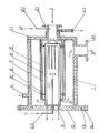
Die Erfindung wird anhand eines Ausführungsbeispieles und einer Zeichnung, die den Schnitt durch die erfindungsgemäße Vorrichtung zeigt, näher erläutert.The invention is explained in more detail using an exemplary embodiment and a drawing which shows the section through the device according to the invention.
Die erfindungsgemäße Vorrichtung besteht im wesentlichen aus einem im Abgasstrom einer Plasmaätzanlage zwischen der Anlage und dem Vakuumpumpsystem angeordneten, als Reaktionskammer 1 ausgebildeten, zylinderförmigen Hohlkörper, der an einer Stirnseite einen Boden 1,1 mit einer darin axial angeordneten Gaseinlaßöffnung 2 aufweist. Die Wandung der Reaktionskammer 1 ist doppelt ausgebildet und für ein Kühlmedium vorgesehen, das über einen Zufluß 4 dem Kühlraum zugeführt wird. Zur Erzielung einer ausreichenden Kühlung ist der Abfluß 4.1 an einer dem Zufluß 4 gegenüberliegenden und am weitesten entfernten Position angeordnet. Gegenüber dem Boden 1.1 ist die Reaktionskammer 1 mit einem Flanschdeckel 10 mittels Dichtring 13 und Schrauben 14 verschließbar.The device according to the invention essentially consists of a cylindrical hollow body which is arranged in the exhaust gas stream of a plasma etching system between the system and the vacuum pump system and is designed as a reaction chamber 1 and has a bottom 1. 1 with an axially arranged gas inlet opening 2 on one end face. The wall of the reaction chamber 1 is double and is provided for a cooling medium which is fed to the cooling space via an inflow 4. In order to achieve sufficient cooling, the drain 4.1 is arranged at a position which is opposite and the most distant from the inflow 4. Compared to the bottom 1.1, the reaction chamber 1 can be closed with a
Im Innern der Reaktionskammer 1 ist ein weiterer zylinderförmiger Hohlkörper axial angeordnet, der als Feststoffkörper 7 ausgebildet und einseitig mit einem Boden 1.1 verschlossen ist. Der Boden 1.1 befindet sich zum Zweck der Abgasreinigung gegenüber der inneren öffnung der Gaseinlaßöffnung 2, während seine offene Seite in einem Abstand von dem Flanschdeckel 10 angeordnet ist. Im Innenraum des Feststoffkörpers 7 ist eine Heizeinrichtung 9 vorgesehen, deren Wendel in der Nähe des Bodens 1.1 des Feststoffkörpers 7 liegt, die Durchführungen für die elektrischen Anschlüsse befinden sich im Flanschdeckel 10, so daß beim öffnen desselben die Heizeinrichtung 9 komplett aus dem Feststoffkörper 7 entfernt werden kann. Des weiteren ist in dem Flanschdeckel 10 eine Rohrleitung 11.2 vorgesehen, deren eine öffnung 11.1 innerhalb des Feststoffkörpers 7 angeordnet ist, während durch die andere Seite eine Verbindung mit einer Einrichtung zur Zuführung eines Spülgases 11 hergestellt wird. Die Befestigung des Feststoffkörpers 7 erfolgt innerhalb der Reaktionskammer 1 derart, daß sich um den Feststoffkörper 7 ein als Strahlenschutz 6 ausgebildeter Hohlzylinder mittels innerer Stützen 8 auf der Wandung des Feststoffkörpers 7 abstandsweise abstützt und dieser Hohlzylinder des Strahlenschutzes 6 an seiner Außenwand und, den inneren Stützen 8 gegenüberliegend, äußere Stützen 8.1 aufweist, die mit einem weiteren Zylinder korrespondieren, der als Stützkörper 5 ausgebildet und mit der Wandung des Bodens 1.1 der Reaktionskammer 1 fest verbunden ist. Im Bereich der Gaseinlaßöffnung 2 oder direkt in dessen Gaseinlaßstutzen 2.1 ist eine weitere Öffnung vorgesehen, durch die über eine Rohrleitung 12.1 ein Reaktionsgas 12 dem Abgas zugeführt werden kann.In the interior of the reaction chamber 1, a further cylindrical hollow body is arranged axially, which is designed as a
Für das vorliegende Ausführungsbeispiel besteht der Feststoffkörper 7 aus Eisen, als Spülgas 11 wird Argon und als Reaktionsgas 12 Sauerstoff eingesetzt. Das Spülgas 11 ist als Abschirmung für die frei im Feststoffkörper 7 angeordnete Heizwendel der Heizeinrichtung 9 zur Vermeidung von Korrosionsschäden an derselben vorgesehen.For the present exemplary embodiment, the
Es ist vorteilhaft, wenn zur Vermeidung von Temperaturverlusten das Spülgas 11 vorgewärmt dem Feststoffkörper 7 zugeführt wird. Die Abführung des behandelten Abgases 3 erfolgt über einen an der Wandung der Reaktionskammer 1 angeordneten Abgasstutzen 3.1.It is advantageous if the purging gas 11 is supplied preheated to the
Im Rahmen erforderlicher zyklischer Reinigungs- und Außerbetriebsetzungsmaßnahmen wird der Flanschdeckel 10 durch Lösen der Schrauben 14 gelöst und das Eisenchlorid kann mühelos von der Wandung im Innenraum der Reaktionskammer entfernt werden. Dazu kann ebenfalls der lose mittels der Stützen 8, 8.1 im Stützkörper 5 eingelegte Feststoffkörper 7 mit dem Strahlenschutz 6 entfernt werden. An dem Feststoffkörper 7 ist deutlich die Reaktion des Chlores mit dem Eisen nachweisbar, woraus der Zeitpunkt des Austausches und die Erneuerung des Feststoffkörpers 7 abgeleitet und durchgeführt werden kann. Ebenso ist es möglich, den Verbrauch des Feststoffkörpers 7 während des Betriebes mittels Sensoren rechtzeitig signalisieren zu lassen oder den aus der Vorrichtung abgeführten Abgasstrom durch entsprechende Meßeinrichtungen zu kontrollieren. Bei einem Nachweis von Chlor oder Chloranteilen ist demzufolge der Feststoffkörper 7 verbraucht und muß zwingend ersetzt werden.As part of the required cyclical cleaning and decommissioning measures, the
Die Vorteile der Vorrichtung ergeben sich insbesondere dadurch, daß das Chlor im Abgas von Plasmaätzanlagen vollständig umgesetzt wird und somit keine schädigenden Anteile aus den Abgasanlagen in die Umwelt abgegeben, Personen belästigt oder geschädigt und Korrosionsschäden verursacht werden.The advantages of the device result in particular from the fact that the chlorine in the exhaust gas from plasma etching systems is completely converted and thus no harmful components are released from the exhaust system into the environment, people are bothered or damaged and corrosion damage is caused.
Claims (12)
Applications Claiming Priority (2)
| Application Number | Priority Date | Filing Date | Title |
|---|---|---|---|
| DD26385984A DD237951A3 (en) | 1984-06-06 | 1984-06-06 | DEVICE FOR CLEANING HALOGENOUS POLLUTANTS |
| DD263859 | 1984-06-06 |
Publications (2)
| Publication Number | Publication Date |
|---|---|
| EP0166846A2 true EP0166846A2 (en) | 1986-01-08 |
| EP0166846A3 EP0166846A3 (en) | 1987-04-15 |
Family
ID=5557707
Family Applications (1)
| Application Number | Title | Priority Date | Filing Date |
|---|---|---|---|
| EP85100094A Withdrawn EP0166846A3 (en) | 1984-06-06 | 1985-01-07 | Device for purifying halogen containing off-gases |
Country Status (3)
| Country | Link |
|---|---|
| EP (1) | EP0166846A3 (en) |
| JP (1) | JPS6157222A (en) |
| DD (1) | DD237951A3 (en) |
Cited By (9)
| Publication number | Priority date | Publication date | Assignee | Title |
|---|---|---|---|---|
| EP0176295A2 (en) * | 1984-09-17 | 1986-04-02 | Randall Mundt | Eliminating unwanted material from a gas flow line |
| EP0296720A3 (en) * | 1987-06-23 | 1989-08-02 | Kin-Chung Ray Chiu | Plasma extraction reactor and its use for vapor extraction from gases |
| EP0346893A1 (en) * | 1988-06-15 | 1989-12-20 | Centrotherm Elektrische Anlagen Gmbh + Co. | Apparatus for purifying exhaust gases emitted in CVD processes |
| WO1993013851A1 (en) * | 1992-01-16 | 1993-07-22 | Leybold B.V. | Method, dry multi-stage pump and plasma scrubber for converting reactive gases |
| US5735919A (en) * | 1995-12-14 | 1998-04-07 | Suntec System Co., Ltd. | Exhaust gas processing system |
| US6041623A (en) * | 1998-08-27 | 2000-03-28 | Lucent Technologies Inc. | Process for fabricating article comprising refractory dielectric body |
| US6576202B1 (en) | 2000-04-21 | 2003-06-10 | Kin-Chung Ray Chiu | Highly efficient compact capacitance coupled plasma reactor/generator and method |
| US9599110B2 (en) | 2011-10-19 | 2017-03-21 | Adixen Vacuum Products | Gas pumping and treatment device |
| US20220299137A1 (en) * | 2021-03-19 | 2022-09-22 | Tokyo Electron Limited | Pipe connection structure and processing apparatus |
Families Citing this family (2)
| Publication number | Priority date | Publication date | Assignee | Title |
|---|---|---|---|---|
| FR2623728B1 (en) * | 1987-11-30 | 1990-04-06 | Air Liquide | |
| DE4444273C1 (en) * | 1994-12-13 | 1996-06-27 | Umex Gmbh | Removal of halogen(s) from exhaust gas |
Citations (2)
| Publication number | Priority date | Publication date | Assignee | Title |
|---|---|---|---|---|
| DE2002537B2 (en) * | 1970-01-21 | 1971-04-15 | Vaw Ver Aluminium Werke Ag | PROCESS FOR SEPARATION OF GASEOUS HYDROGEN FROM EXHAUST GASES |
| DE2015996A1 (en) * | 1970-03-26 | 1971-10-14 | Richard Kablitz Ges F Oekonomi | Purifying combustion gas contg chlorine |
-
1984
- 1984-06-06 DD DD26385984A patent/DD237951A3/en not_active IP Right Cessation
-
1985
- 1985-01-07 EP EP85100094A patent/EP0166846A3/en not_active Withdrawn
- 1985-06-06 JP JP60121626A patent/JPS6157222A/en active Pending
Patent Citations (2)
| Publication number | Priority date | Publication date | Assignee | Title |
|---|---|---|---|---|
| DE2002537B2 (en) * | 1970-01-21 | 1971-04-15 | Vaw Ver Aluminium Werke Ag | PROCESS FOR SEPARATION OF GASEOUS HYDROGEN FROM EXHAUST GASES |
| DE2015996A1 (en) * | 1970-03-26 | 1971-10-14 | Richard Kablitz Ges F Oekonomi | Purifying combustion gas contg chlorine |
Cited By (15)
| Publication number | Priority date | Publication date | Assignee | Title |
|---|---|---|---|---|
| EP0176295A2 (en) * | 1984-09-17 | 1986-04-02 | Randall Mundt | Eliminating unwanted material from a gas flow line |
| EP0176295A3 (en) * | 1984-09-17 | 1988-01-07 | Randall Mundt | Eliminating unwanted material from a gas flow line |
| EP0296720A3 (en) * | 1987-06-23 | 1989-08-02 | Kin-Chung Ray Chiu | Plasma extraction reactor and its use for vapor extraction from gases |
| EP0346893A1 (en) * | 1988-06-15 | 1989-12-20 | Centrotherm Elektrische Anlagen Gmbh + Co. | Apparatus for purifying exhaust gases emitted in CVD processes |
| WO1993013851A1 (en) * | 1992-01-16 | 1993-07-22 | Leybold B.V. | Method, dry multi-stage pump and plasma scrubber for converting reactive gases |
| US5672322A (en) * | 1992-01-16 | 1997-09-30 | Leybold Ag | Method, dry multi-stage pump and plasmascrubber for converting reactive gases |
| US5735919A (en) * | 1995-12-14 | 1998-04-07 | Suntec System Co., Ltd. | Exhaust gas processing system |
| US6041623A (en) * | 1998-08-27 | 2000-03-28 | Lucent Technologies Inc. | Process for fabricating article comprising refractory dielectric body |
| US6576202B1 (en) | 2000-04-21 | 2003-06-10 | Kin-Chung Ray Chiu | Highly efficient compact capacitance coupled plasma reactor/generator and method |
| US6998027B2 (en) | 2000-04-21 | 2006-02-14 | Dryscrub, Etc | Highly efficient compact capacitance coupled plasma reactor/generator and method |
| US7241428B2 (en) | 2000-04-21 | 2007-07-10 | Dryscrub, Etc | Highly efficient compact capacitance coupled plasma reactor/generator and method |
| US9599110B2 (en) | 2011-10-19 | 2017-03-21 | Adixen Vacuum Products | Gas pumping and treatment device |
| TWI610024B (en) * | 2011-10-19 | 2018-01-01 | 艾迪生真空產品公司 | Device for pumping and treating gases |
| US20220299137A1 (en) * | 2021-03-19 | 2022-09-22 | Tokyo Electron Limited | Pipe connection structure and processing apparatus |
| US11774017B2 (en) * | 2021-03-19 | 2023-10-03 | Tokyo Electron Limited | Pipe connection structure and processing apparatus |
Also Published As
| Publication number | Publication date |
|---|---|
| EP0166846A3 (en) | 1987-04-15 |
| DD237951A3 (en) | 1986-08-06 |
| JPS6157222A (en) | 1986-03-24 |
Similar Documents
| Publication | Publication Date | Title |
|---|---|---|
| DE19802404B4 (en) | Device for gas purification and method for the treatment of a gas to be cleaned | |
| DE3513731C2 (en) | ||
| EP0702771B1 (en) | Exhaust gas cleaning installation | |
| DE60132089T2 (en) | DEVICE FOR TREATING GASEN MIITELS PLASMA | |
| EP0166846A2 (en) | Device for purifying halogen containing off-gases | |
| DE4319118A1 (en) | Process and apparatus for disposing of fluorocarbons and other fluorine-containing compounds | |
| DE2647088B2 (en) | Method and device for cleaning surfaces | |
| EP0402798A2 (en) | Coating device | |
| EP1083978A1 (en) | Method for purifying process waste gases | |
| EP0508338A1 (en) | Method and device for degrading organic contaminants by means of photolysis | |
| DE3230922A1 (en) | METHOD FOR TREATING SUBSTANCES WITH OZONE | |
| EP0347753B1 (en) | Process for purifying waste gazes from cvd-processes | |
| DE19631873C1 (en) | Apparatus for purifying waste gases | |
| DE3432033C2 (en) | Process and arrangement for the detoxification of F-carbon-containing exhaust gases | |
| DE10312309A1 (en) | Device and method for purifying of discharged air, comprising high frequency field for creation of plasma | |
| EP0487834A1 (en) | Oxidative washing process for cleaning waste gases | |
| DE19807632A1 (en) | Device for concentrating and purifying sulfuric acid | |
| EP0735321B1 (en) | Process for purification of noxious exhaust gases by chemical conversion | |
| DE4016514C2 (en) | ||
| EP0340379A2 (en) | Process for cleaning soil contaminated by hydrophobic organic substances | |
| EP0735320B1 (en) | Process and device for purification of noxious exhaust gases by chemical conversion | |
| EP0502303A1 (en) | Process for treating objects with a gas comprising fluor, and apparatus for carrying out the process | |
| DE69734784T2 (en) | METHOD FOR THE TREATMENT OF EXHAUST GAS CONTAINING HALOGEN CONNECTION | |
| EP1210468B1 (en) | Method for cleaning a pvd or cvd reactor and waste-gas lines of the same | |
| EP0656322B1 (en) | Purification system |
Legal Events
| Date | Code | Title | Description |
|---|---|---|---|
| PUAI | Public reference made under article 153(3) epc to a published international application that has entered the european phase |
Free format text: ORIGINAL CODE: 0009012 |
|
| AK | Designated contracting states |
Designated state(s): AT CH DE FR IT LI NL |
|
| PUAL | Search report despatched |
Free format text: ORIGINAL CODE: 0009013 |
|
| AK | Designated contracting states |
Kind code of ref document: A3 Designated state(s): AT CH DE FR IT LI NL |
|
| STAA | Information on the status of an ep patent application or granted ep patent |
Free format text: STATUS: THE APPLICATION IS DEEMED TO BE WITHDRAWN |
|
| 18D | Application deemed to be withdrawn |
Effective date: 19870203 |
|
| RIN1 | Information on inventor provided before grant (corrected) |
Inventor name: VOIGT, REINHARD Inventor name: WEBER, ULF Inventor name: FENDLER, REINHARD, DR. Inventor name: BERG, DOROTHEA, DR. Inventor name: LEHMANN, KLAUS-JUERGEN Inventor name: HELBIG, JUERGEN Inventor name: TILLER, HANS-JUERGEN |