EP0166234A2 - Connection box for water supply installations - Google Patents
Connection box for water supply installations Download PDFInfo
- Publication number
- EP0166234A2 EP0166234A2 EP85106447A EP85106447A EP0166234A2 EP 0166234 A2 EP0166234 A2 EP 0166234A2 EP 85106447 A EP85106447 A EP 85106447A EP 85106447 A EP85106447 A EP 85106447A EP 0166234 A2 EP0166234 A2 EP 0166234A2
- Authority
- EP
- European Patent Office
- Prior art keywords
- angle
- socket
- flange
- box
- connection
- Prior art date
- Legal status (The legal status is an assumption and is not a legal conclusion. Google has not performed a legal analysis and makes no representation as to the accuracy of the status listed.)
- Granted
Links
- 238000009434 installation Methods 0.000 title claims abstract description 30
- XLYOFNOQVPJJNP-UHFFFAOYSA-N water Substances O XLYOFNOQVPJJNP-UHFFFAOYSA-N 0.000 title abstract description 6
- 230000001681 protective effect Effects 0.000 claims abstract description 14
- 230000006835 compression Effects 0.000 claims abstract description 4
- 238000007906 compression Methods 0.000 claims abstract description 4
- 229920002457 flexible plastic Polymers 0.000 claims abstract description 3
- 239000011505 plaster Substances 0.000 claims abstract 3
- 238000003780 insertion Methods 0.000 claims description 12
- 230000037431 insertion Effects 0.000 claims description 12
- 239000008235 industrial water Substances 0.000 claims description 3
- 238000007789 sealing Methods 0.000 claims 1
- 239000011093 chipboard Substances 0.000 abstract description 3
- 230000008878 coupling Effects 0.000 abstract 1
- 238000010168 coupling process Methods 0.000 abstract 1
- 238000005859 coupling reaction Methods 0.000 abstract 1
- 229920003023 plastic Polymers 0.000 description 20
- 238000010276 construction Methods 0.000 description 6
- 239000002023 wood Substances 0.000 description 3
- 229910000831 Steel Inorganic materials 0.000 description 2
- 230000001154 acute effect Effects 0.000 description 2
- 230000002950 deficient Effects 0.000 description 2
- 239000010959 steel Substances 0.000 description 2
- 239000000853 adhesive Substances 0.000 description 1
- 230000001070 adhesive effect Effects 0.000 description 1
- 238000005452 bending Methods 0.000 description 1
- 238000011161 development Methods 0.000 description 1
- 230000018109 developmental process Effects 0.000 description 1
- 230000009977 dual effect Effects 0.000 description 1
- 230000000694 effects Effects 0.000 description 1
- 230000002349 favourable effect Effects 0.000 description 1
- 238000011900 installation process Methods 0.000 description 1
- 238000004519 manufacturing process Methods 0.000 description 1
- 239000002184 metal Substances 0.000 description 1
- 238000000034 method Methods 0.000 description 1
- 239000004570 mortar (masonry) Substances 0.000 description 1
- 230000002441 reversible effect Effects 0.000 description 1
- 230000007704 transition Effects 0.000 description 1
Images


Classifications
-
- E—FIXED CONSTRUCTIONS
- E03—WATER SUPPLY; SEWERAGE
- E03C—DOMESTIC PLUMBING INSTALLATIONS FOR FRESH WATER OR WASTE WATER; SINKS
- E03C1/00—Domestic plumbing installations for fresh water or waste water; Sinks
- E03C1/02—Plumbing installations for fresh water
- E03C1/021—Devices for positioning or connecting of water supply lines
Definitions
- the invention relates to a junction box for industrial water installations according to the preamble of claim 1.
- plastic pipes are increasingly used instead of metal pipes for service water installations.
- the plastic pipes are laid in protective or insulating pipes.
- taps wash basins, cisterns, etc.
- So-called socket angles are attached by means of commercially available clamping ring screw connections, which in turn are immovably fixed in junction boxes made of plastic.
- junction boxes In the socket angle there is a connection thread into which the sanitary fittings such as surface-mounted valves (corner valves, batteries) are screwed.
- the junction boxes are anchored in the masonry (plastered) or fastened to plates (plasterboard, wood).
- the protective or insulating pipes connect directly to the junction boxes.
- the old pipe can be pulled out of the junction box and the protective pipe.
- the new tube is then reinserted from the can.
- Sufficiently large installation radii are a requirement, since the plastic pipes are very stiff and not very flexible.
- a junction box for industrial water installations is known, for example, from German utility model 77 05 225.6 and from European patent application 85 329.
- a disadvantage of the known junction boxes is that they are only designed for one area of use and for different areas of use
- the socket angle is fastened in the socket body, for example with two screws or with a union nut or with a large threaded plug made of plastic. As a result, the assembly of the can angle is time-consuming.
- the invention has for its object to provide a junction box for domestic water installations, which is suitable for all applications.
- the junction box to be created should also be easy to assemble, with a tight fit of the box angle in the box body being ensured.
- the junction box according to the invention has one and the same box body and one and the same box angle for all applications - flush mounting, arrangement for pre-wall installation, attachment to lightweight or wooden panel walls or attachment to a concealed cistern.
- the socket body has fastening flanges on both its front and rear sides with through-openings and / or threaded openings for the passage or screwing in of fastening screws / bolts.
- the can body is attached over the front or over the rear fastening flange, whereby fastening screws are passed through the through openings or screwed into the threaded openings.
- the can angle In the assembled position, the can angle is firmly attached to all sides of the can angle due to the interacting contact surfaces and in the can body. It only has to be locked from the insertion side, for which purpose an elastically yielding catch can be formed on the can body, for example, which projects in front of a nose of the can angle in the assembled or installed position of the can angle.
- Other catches are also conceivable, for example steel springs or rings fastened in the box. Fastening with a screw is also possible, whereby one screw is sufficient since the socket angle is firmly attached on all sides.
- connection thread on the socket angle in front of the plane of the front fastening flange and by eccentric arrangement of the socket angle connection thread result in a flat construction of the connection box and favorable assembly and disassembly conditions by preventing the plastic tube from being bent excessively.
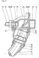
- Fig. 1 shows the junction box 1 in longitudinal section with the socket body 2 and the socket angle 3 used.
- the socket angle 3 has a (generally known) clamping ring screw connection 4 for connecting a flexible plastic pipe for service water.
- the clamping ring connection is located inside the screw connection 4 as far as possible from the screw end 6, so that the hose end 7 projects far into the screw connection.
- the plastic tube 5 is not curved so much because its end 7 is already close to the insertion opening of the can body 2.
- a lower cylinder jacket surface 8 of the screw connection 4 is enclosed on all sides by a cylinder jacket in the installation position of the can angle shown Surface 9 on the can body 2. There is play of approx. 0.2 mm between the two surfaces.
- An upper cylinder jacket surface 10 of the screw connection 4 lies against the jacket surface 11 ′′ of a partial cylinder of the can body 2. All cylinder jacket surfaces have a common axis 11.
- the axis 11 is at an obtuse angle to axes 12 and 13, which run parallel to one another (see also FIG. 7 and 8.
- the axis 13 is the center of a cylinder flange 33 at the can angle 3.
- the cylindrical surface 14 of the flange 33 lies up to the middle 16-17 (FIGS.
- Axis 12 is the central axis of the connecting thread 21 of the can angle 3.
- the nozzle or corner valve (not shown) is egg screwed. The water thus flows through the plastic tube 5 and bores 22 and 23 within the can angle into the valve.
- the compression fitting 4 has a dual function by: serves on the one hand for connecting the plastic tube 5 and on the other hand with its outer cylindrical surfaces as a centering and supporting element.
- the can angle 3 is held by a locking lever 24 (FIGS. 1, 7 and 8).
- the lower end of the locking lever 24 is firmly connected to the side wall 25 of the can body 2 up to a bending point 26 (see also FIG. 2).
- the catch 28 lies in the installation position of the can angle 3 shown in FIG. 1 with its surface 29 over the surface 30 of a nose 31 of the can angle 3, so that the can angle is secured against being pulled out upwards.
- Another fuse is shown in FIG. 3.
- a screw 32 (see also FIGS. 7 and 8), the head of which is seated in or on the flange 33 of the can bracket 3, is screwed into a nut 34 which is firmly cast into the can body 2.
- a single screw is sufficient for securing, since the socket angle 3 is otherwise held in a positive manner in all directions.
- the locking lever can then be omitted.
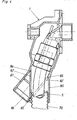
- Fig. 2 shows the can angle 3 with connected plastic tube 5 in a partially installed or removed state.
- the can angle 3 is pushed further into the can body 2 until the central axis 11 'of the can angle 3 coincides with the axis 11 (FIG. 1) and the upper vertex 35 of the end face 18 of the flange 33 at a slope 36 of the insertion opening of the can body 2 is present.
- the screw end 6 is then in front of the cylindrical surface 9 of the can body 2.
- By moving the can angle 3 in the direction of the axis 11 downwards it is brought into its final position.
- the apex 35 of the end face 18 of the cylinder flange 33 slides along the bevel 36 of the insertion opening of the can body 2.
- the bevel 36 is delimited by the inner semicircular arch 37 at the transition to the collar 20 and through the outer oval 38, which begins in the middle 16-17 (Figs. 7 and 8).
- the bevel 36 runs parallel to the axis 11.
- the locking lever 24 is pushed back by the clamping ring screw connection 4 during the introduction of the can angle 3 (FIG. 2), ie it deforms elastically. Did he. Can angle 3 reaches its final position, the locking lever 24 springs back and the locking 28 comes to rest over the nose 31 of the can angle 3 and locks it against being pulled out.
- the locking is released by pushing the locking lever 24 back with a screwdriver or the like.
- an opening 27 (FIGS. 2, 7 and 8) is provided in the front wall of the can body 2, through which the screwdriver can be inserted.
- the can angle 3 is then pulled out in the reverse order of the insertion.
- the removal and installation process of the can angle 3 is hampered by the round opening 39 in the wall structure (masonry, lightweight wall). This can be clearly seen in FIG. 2.
- the opening 39 must be smaller than the decorative rosette that covers the opening 39 after the finished installation.
- the opening 39 can be given the required small diameter. If the axis 12 of the connecting thread 21 coincided with the axis 13 of the flange 33 (central arrangement), the upper boundary line of the opening 39 could also not be lowered, since the upper apex 35 of the end face 18 of the flange 33 continues would lie in the same place (Fig. 2).
- the plastic tube 5 When inserting or pulling out the can angle 3 into or out of the can body 2, the plastic tube 5 is slightly curved due to the obtuse-angled arrangement of the axis 11 to the axes 12, 13, which, since the plastic tube is thick-walled and unwilling to bend, makes handling easier means.
- This obtuse-angled arrangement of the axis 11 to the axes 12, 13 is possible - without a large installation depth of the junction box 1 being necessary - by the arrangement of the connecting thread 21 in the assembled position of the box angle 3 essentially outside the insertion opening of the box body 2.
- Box dimensions which are as flat as possible should be aimed at in order to achieve small hole dimensions for inserting the box into the masonry, which require little chiseling work.
- the described junction box 1 can be used universally for the various applications.
- a fastening flange 40, 59 (FIG. 7) or 40 ', 59' (FIG. 8) is provided for the different fastening methods on the front and rear.
- 44 ', 45', 46 '(FIG. 8) fastening screws 47, 48, 49 (FIG. 2), 50, 51, 52 (FIG. 1) and 53, 54, 55 (FIGS. 5 and 6) are carried out or screwed in.
- the attachment of the junction box 1 to a plasterboard 66 shows Fig. L. Tiles 67 and the tile adhesive 68 are also shown in section.
- the box 1 is fastened with screws 50, 51, 52, the countersunk heads of which rest on a self-contained steel ring 69 and in nuts 44, 45, 46 (FIG. 7) or 44 ', 45', 46 '(Fig. 8) are screwed, which are cast in the can bodies 2.
- junction box 1 for flush mounting is also shown in FIG. 1.
- a hole is made in the masonry, the box 1 is inserted and walled in, an attachment to the front flange 40, 40 'is omitted.
- a protective tube 70 which encloses the plastic tube 5, is also laid and plastered in the masonry.
- the screws are seated in bores 62, 63 (FIG. 7) and 62 ', 63' (FIG. 8) of the rear fastening flange 59 and 59 ', respectively.
- FIG. 2 the use of the junction box 1 is shown in a wooden panel wall construction. On average, the wall components with wood chipboard 87, plasterboard 88 and tiles 89 are indicated.
- the box 1 is fastened to the wood chipboard 87 with screws 47, 48, 49, which protrude through bores in the front fastening flange 40 or 40 '.
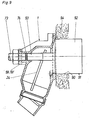
- FIG. 3 The arrangement of the box 1 for pre-wall installation is shown in FIG. 3.
- the box is fastened to the rear wall with a fastening bolt 73 so that its front flange 40 or 40 'approximately closes with the front wall.
- a thread 74 is provided in the rear fastening flange 59 or 59 ', the central axis 75 of which is aligned with the central axis 12 of the connecting thread 21.
- a lock nut 76 secures the can 1 against twisting.
- the protective tube 70 which surrounds the plastic tube 5, is laid in the free space between the two walls. The protective tube 70 should therefore not be directed vertically downward, as shown in FIG. 1, but at an acute angle to the rear.
- a guide part 77 in which the protective tube 70 is inserted, is rotatably mounted on a cylinder stub 78 of the junction box 1 and can be rotated from the position shown in FIG. 1, for example to the position corresponding to FIG. 3, so that the protective tube 70 and with it the plastic tube 5 takes the direction desired for pre-wall installation.
- a shoulder 79 on the cylinder neck 78 prevents the guide member 77 from sliding down.
- Figures 5 and 6 show the attachment of the junction box 1 to a concealed cistern 56.
- the box 1 is screwed by screws 53, 54, 55, which are screwed into the nuts 44, 45, 46 and 44 ', 45', 46 ' are attached to the outside of the .57 cistern wall.
- 6 shows a longitudinal section of the can 1 and the cistern wall 57.
- a FOG. 5
- the mounting flange must not be wider than twice the distance a.
- FIG. 8 Another possibility of designing narrow fastening flanges without breakable outer parts is shown in FIG. 8.
- the bores 41 ', 42' and 62 ', 63' are open on the side. The openings do not extend to the central axis of the bores, so that the screws are held against slipping out sideways.
- Local recesses 64, 65 are additionally provided in the side walls 25, 25 'of the can body for the screw heads.
- an opening 90 (FIG. 9) corresponding to the opening 39 in FIG. 2, which will later be covered with the decorative rosette, must be left in the masonry.
- the plastering is started a plastic plug 91 inserted into the can of the can.
- the cylindrical part 92 of the plug 91 has the diameter of the desired opening in the masonry.
- the plug 91 is screwed with a threaded connector 93 into the central thread 74, in the other end of which the fastening bolt 73 (see also FIG. 3) is used, which is used for pre-wall installation.
- the thread 74 of the rear fastening flange 59 or 59 'thus fulfills two functions. After the mortar 94 has set, the plug 91 is unscrewed.
- the thread 74 can be closed with a plug 95 (FIG. 2) in order to prevent the ingress of dirt.
Landscapes
- Health & Medical Sciences (AREA)
- Life Sciences & Earth Sciences (AREA)
- Engineering & Computer Science (AREA)
- Hydrology & Water Resources (AREA)
- Public Health (AREA)
- Water Supply & Treatment (AREA)
- Connection Or Junction Boxes (AREA)
- Laying Of Electric Cables Or Lines Outside (AREA)
- Devices That Are Associated With Refrigeration Equipment (AREA)
- Domestic Plumbing Installations (AREA)
- Forms Removed On Construction Sites Or Auxiliary Members Thereof (AREA)
Abstract
Description
Die Erfindung betrifft eine Anschlußdose für Brauchwasser-Installationen gemäß dem Oberbegriff des Anspruchs 1.The invention relates to a junction box for industrial water installations according to the preamble of
Im Sanitärbereich verwendet man für Brauchwasser-Installationen verstärkt Kunststoffrohre anstelle von Metallrohren. Die Kunststoffrohre werden in Schutz-oder Isolierrohren verlegt. An den Zapfstellen (Waschbecken, Spülkästen usw.) werden an die Enden der Kunststoffrohre z.B. mittels handelsüblicher Klemmring-Verschraubungen sogenannte Dosenwinkel angebracht, die ihrerseits unverrückbar in Anschlußdosen aus Kunststoff festgelegt werden. Im Dosenwinkel befindet sich ein Anschlußgewinde, in das die Sanitärarmaturen wie Aufputz-Ventile (Eckventile, Batterien) geschraubt werden. Die Anschlußdosen werden im Mauerwerk verankert (eingeputzt) oder bei Leichtbauweise an Platten (Gipskarton, Holz) befestigt. Die Schutz- bzw. Isolierrohre schließen unmittelbar an die Anschlußdosen an. Muß später ein defektes Rohr gewechselt werden, kann somit das alte Rohr aus der Anschlußdose und dem Schutzrohr herausgezogen werden. Anschließend wird das neue Rohr von der Dose aus wieder eingeführt. Voraussetzung sind genügend große Verlege-Radien, da die Kunststoffrohre sehr steif und wenig flexibel sind.In the sanitary area, plastic pipes are increasingly used instead of metal pipes for service water installations. The plastic pipes are laid in protective or insulating pipes. At the taps (wash basins, cisterns, etc.) at the ends of the plastic pipes e.g. So-called socket angles are attached by means of commercially available clamping ring screw connections, which in turn are immovably fixed in junction boxes made of plastic. In the socket angle there is a connection thread into which the sanitary fittings such as surface-mounted valves (corner valves, batteries) are screwed. The junction boxes are anchored in the masonry (plastered) or fastened to plates (plasterboard, wood). The protective or insulating pipes connect directly to the junction boxes. If a defective pipe has to be replaced later, the old pipe can be pulled out of the junction box and the protective pipe. The new tube is then reinserted from the can. Sufficiently large installation radii are a requirement, since the plastic pipes are very stiff and not very flexible.
Eine Anschlußdose für Brauchwasser-Installationen ist beispielsweise aus dem deutschen Gebrauchsmuster 77 05 225.6 sowie aus der europäischen Patentanmeldung 85 329 bekannt. Nachteilig an den bekannten Anschlußdosen ist, daß sie jeweils nur für einen Einsatzbereich konzipiert sind, und für verschiedene Einsatzbereiche wie Unterputzeinbau, Anordnung bei Vorwand-Installation, Befestigung an Leichtbau- oder Holzplattenwänden oder Anbau an einen Unterputz-Spülkasten gibt es verschiedene Anschlußdosen und die dazu passenden Dosenwinkel. Die Herstellung und Lagerhaltung sind dadurch verteuert. Die Befestigung des Dosenwinkels im Dosenkörper erfolgt bei den bekannten Anschlußdosen z.B. mit zwei Schrauben oder mit Überwurfmutter oder mit großem Gewindestopfen aus Kunststoff. Dadurch ist die Montage des Dosenwinkels zeitaufwendig.A junction box for industrial water installations is known, for example, from
Beim Herausziehen eines defekten bzw. beim Einsetzen eines neuen Rohres wird das Rohr bei den bekannten Dosen zum Teil stark gekrümmt. Dies erschwert den Aus- und Einbau des Rohres.When a defective tube is pulled out or a new tube is inserted, the tube in the known cans is in part severely curved. This complicates the removal and installation of the pipe.
Der Erfindung liegt die Aufgabe zugrunde, eine Anschlußdose für Brauchwasser-Installationen zu schaffen, die sich für alle Anwendungsfälle eignet. Die zu schaffende Anschlußdose soll auch einfach in der Montage sein, wobei ein fester Sitz des Dosenwinkels im Dosenkörper gewährleistet sein soll.The invention has for its object to provide a junction box for domestic water installations, which is suitable for all applications. The junction box to be created should also be easy to assemble, with a tight fit of the box angle in the box body being ensured.
Die gestellte Aufgabe wird erfindungsgemäß mit einer Anschlußdose gelöst, wie sie durch den Anspruch 1 gekennzeichnet ist. Weiterbildungen der Erfindung sind in den Unteransprüchen beschrieben.The object is achieved according to the invention with a junction box as characterized by
Die Anschlußdose nach der Erfindung hat ein-und denselben Dosenkörper und ein und denselben Dosenwinkel für alle Anwendungsfälle - Unterputzeinbau, Anordnung bei Vorwand-Installation, Befestigung an Leichtbau- oder Holzplattenwänden oder Anbau an einen Unterputz-Spülkasten. Hierzu weist der Dosenkörper Befestigungsflansche sowohl an seiner Vorder- als auch an seiner Rückseite mit Durchgangsöffnungen und/ oder Gewindeöffnungen zum Durchführen bzw. Einschrauben von Befestigungsschrauben/-bolzen auf. Je nach Anwendungsfall erfolgt das Befestigen des Dosenkörpers über den vorderen oder über den hinteren Befestigungsflansch, wobei Befestigungsschrauben durch die Durchgangsöffnungen durchgeführt oder in die Gewindeöffnungen eingeschraubt werden.The junction box according to the invention has one and the same box body and one and the same box angle for all applications - flush mounting, arrangement for pre-wall installation, attachment to lightweight or wooden panel walls or attachment to a concealed cistern. For this purpose, the socket body has fastening flanges on both its front and rear sides with through-openings and / or threaded openings for the passage or screwing in of fastening screws / bolts. Depending on the application, the can body is attached over the front or over the rear fastening flange, whereby fastening screws are passed through the through openings or screwed into the threaded openings.
Der Dosenwinkel sitzt in der montierten Stellung auf Grund zusammenwirkenden Anlageflächen am Dosenwinkel und im Dosenkörper allseitig unverrückbar fest. Nur von der Einführungsseite her muß er arretiert werden, wofür beispielsweise am Dosenkörper eine elastisch nachgebende Raste ausgebildet sein kann, die in der montierten oder Einbaustellung des Dosenwinkels vor eine Nase des Dosenwinkels vorspringt. Es sind auch andere Rastungen denkbar, zum Beispiel in der Dose befestigte Stahlfedern oder -ringe. Möglich ist auch die Befestigung durch eine Schraube, wobei eine Schraube genügt, da der Dosenwinkel allseitig fest sitzt.In the assembled position, the can angle is firmly attached to all sides of the can angle due to the interacting contact surfaces and in the can body. It only has to be locked from the insertion side, for which purpose an elastically yielding catch can be formed on the can body, for example, which projects in front of a nose of the can angle in the assembled or installed position of the can angle. Other catches are also conceivable, for example steel springs or rings fastened in the box. Fastening with a screw is also possible, whereby one screw is sufficient since the socket angle is firmly attached on all sides.
Durch eine vorspringende Anordnung des Anschlußgewindes am Dosenwinkel vor die Ebene des vorderen Befestigungsflansches sowie durch exzentrische Anordnung des Dosenwinkel-Anschlußgewindes ergeben sich eine flache Bauweise der Anschlußdose und günstige Montage-und Demontagebedingungen, indem ein starkes Verbiegen des Kunststoffrohres verhindert wird.A projecting arrangement of the connection thread on the socket angle in front of the plane of the front fastening flange and by eccentric arrangement of the socket angle connection thread result in a flat construction of the connection box and favorable assembly and disassembly conditions by preventing the plastic tube from being bent excessively.
Die Erfindung wird nachfolgend in Ausführungsbeispielen anhand beigefügter Zeichnungen näher erläutert. Es zeigen
- Fig. l im Längsschnitt eine Anschlußdose in montierter Stellung bei Unterputzeinbau bzw. Befestigung an einer Leichtbauwand (Gipskarton);
- -Fig. 2 im Längsschnitt die Anschlußdose von Fig. 1 mit teilweise herausgezogenem Dosenwinkel, jedoch montiert an eine Holzplatten-Wandkonstruktion;
- Fig. 3 im Längsschnitt die Anschlußdose von Fig. 1 in montierter Stellung bei einer Vorwand-Installation (Vormauerung);
- .Fig. 4 im 'Längsschnitt eine Ausführungsvariante einer Anschlußdose mit einem in anderer Weise verstellbaren Führungsteil zum Anschließen des Schutzrohres;
- Fig. 5 in der Draufsicht eine Anschlußdose gemäß Fig. l, angebaut an einen Unterputz-Spülkasten;
- Fig. 6 einen Längsschnitt nach der Linie VI-VI in Fig. 5;
- Fig. 7 eine teilweise geschnittene Vorderansicht der Anschlußdose von Fig. 1 mit einer ersten Variante in der Ausbildung der Befestigungsflansche;
- Fig.7a einen Teilschnitt aus Fig. 7 längs der Linie VIIa-VIIa;
- Fig. 8 eine Vorderansicht der Anschlußdose von Fig. l mit einer zweiten Variante in der Ausbildung der Befestigungsflansche; und
- Fig. 9 im Längsschnitt eine Zwischenphase beim Einbau der Anschlußdose in Unterputz- oder Vorwand-Bauweise.
- Fig. L in longitudinal section a junction box in the assembled position when flush-mounted or attached to a lightweight wall (plasterboard);
- -Fig. 2 in longitudinal section the junction box of Figure 1 with the socket angle partially pulled out, but mounted on a wooden panel wall construction;
- Fig. 3 in longitudinal section the junction box of Fig. 1 in the assembled position with a pretext installation lation (facing);
- .Fig. 4 a longitudinal section of an embodiment variant of a junction box with a guide part which can be adjusted in another way for connecting the protective tube;
- 5 shows a top view of a junction box according to FIG. 1, mounted on a concealed cistern;
- Fig. 6 is a longitudinal section along the line VI-VI in Fig. 5;
- Fig. 7 is a partially sectioned front view of the junction box of Figure 1 with a first variant in the design of the mounting flanges.
- 7a shows a partial section from FIG. 7 along the line VIIa-VIIa;
- Fig. 8 is a front view of the junction box of Figure 1 with a second variant in the design of the mounting flanges. and
- Fig. 9 in longitudinal section an intermediate phase when installing the junction box in flush or pre-wall construction.
Fig. 1 zeigt die Anschlußdose 1 im Längsschnitt mit dem Dosenkörper 2 und dem eingesetzten Dosenwinkel 3. Der Dosenwinkel 3 besitzt eine (allgemein bekannte) Klemmring-Verschraubung 4 zum Anschluß eines flexiblen Kunststoffrohres für Brauchwasser. Die Klemmringverbindung sitzt im Innern der Verschraubung 4 möglichst weit vom Verschraubungsende 6 entfernt, so daß das Schlauchende 7 weit in die Klemmring-Verschraubung hineinragt. Beim Ein- und Ausbau des Dosenwinkels 3 wird dadurch das Kunststoffrohr 5 nicht so stark gekrümmt, da dessen Ende 7 bereits in der Nähe der Einführöffnung des Dosenkörpers 2 liegt.Fig. 1 shows the
Eine untere Zylindermantelfläche 8 der Verschraubung 4 wird in der gezeigten Einbaustellung des Dosenwinkels allseits umschlossen von einer Zylindermantelfläche 9 am Dosenkörper 2. Zwischen beiden Flächen ist Spiel von ca. 0,2 mm. Eine obere Zylindermantelfläche 10 der Verschraubung 4 liegt an der Mantelfläche 11" eines Teilzylinders des Dosenkörpers 2 an. Alle Zylindermantelflächen haben eine gemeinsame Achse 11. Die Achse 11 steht im stumpfen Winkel zu Achsen 12 und 13, die parallel zueinander verlaufen (siehe auch Fig. 7 und 8). Die Achse 13 ist die Mitte eines Zylinderflansches 33 am Dosenwinkel 3. Die Zylindermantelfläche 14 des Flansches 33 liegt bis zur Mitte 16-17 (Fig. 7 und 8) auf der hälftigen Zylindermantelfläche 15 in der Einführöffnung des Dosenkörpers 2 auf. Die rückwärtige Stirnfläche 18 des Zylinderflansches 33 liegt an einer am Dosenkörper ausgebildeten hälftigen Kreisringfläche 19 eines ebenfalls hälftigen Bundes 20 an, der diametral gegenüberliegend zur Zylindermantelfläche 15 von oben bis zur Mitte 16-17 reicht (siehe auch Fig. 7 und 8). Die Achse 12 ist die Mittelachse des Anschlußgewindes 21 des Dosenwinkels 3. In das Anschlußgewinde 21 wird das (nicht dargestellte) Zapf- oder Eckventil eingeschraubt. Das Wasser fließt somit durch das Kunststoffrohr 5 und Bohrungen 22 und 23 innerhalb des Dosenwinkels in das Ventil.A lower
Durch die beschriebenen Anlageflächen (Zylindermantelflächen) ist der Dosenwinkel 3 nach allen Richtungen - bis auf die Herausziehrichtung in der Verlängerung der Achse 11 nach oben - unverrückbar und verdrehsicher innerhalb des Dosenkörpers 2 gehalten. Damit die geringen Spiele (z.B. zwischen den Zylindermantelflächen 8 und 9), die zum bequemen Einsetzen des Dosenwinkels 3 erforderlich sind, sich nur wenig auf den festen Sitz des Dosenwinkels im Dosenkörper auswirken, sind die Abstände der einzelnen Auf- und Anlagepunkte möglichst weit voneinander entfernt gewählt. Die Klemmring-Verschraubung 4 hat eine Doppelfunktion, indem sie einerseits zum Anschließen des Kunststoffrohrs 5 und andererseits mit ihren Außenzylinderflächen als Zentrier-und Stützelement dient.Due to the described contact surfaces (cylinder jacket surfaces), the
In Richtung der Achse 11 nach oben wird der Dosenwinkel 3 durch einen Rasthebel 24 gehalten (Fig. 1, 7 und 8). Der Rasthebel 24 ist mit seinem unteren Ende bis zu einem Biegepunkt 26 fest mit der Seitenwand 25 des Dosenkörpers 2 verbunden (siehe auch Fig. 2). Die Rast 28 liegt in der in Fig. 1 gezeigten Einbaustellung des Dosenwinkels 3 mit ihrer Fläche 29 über der Fläche 30 einer Nase 31 des Dosenwinkels 3, so daß der Dosenwinkel gegen Herausziehen nach oben gesichert ist. Eine andere Sicherung ist in Fig. 3 gezeigt. Eine Schraube 32 (siehe auch Fig. 7 und 8), deren Kopf im oder auf dem Flansch 33 des Dosenwinkels 3 sitzt, wird in eine Mutter 34 geschraubt, die in den Dosenkörper 2 fest eingegossen ist. Es genügt eine einzige Schraube als Sicherung, da der Dosenwinkel 3 ansonsten nach allen Richtungen formschlüssig gehalten ist. Der Rasthebel kann dann entfallen.In the direction of the
Fig. 2 zeigt den Dosenwinkel 3 mit angeschlossenem Kunststoffrohr 5 in teilweise ein- bzw. ausgebautem Zustand. Für den Einbau wird der Dosenwinkel 3 weiter in den Dosenkörper 2 hineingeschoben, bis die Mittelachse 11' des Dosenwinkels 3 sich mit der Achse 11 (Fig. 1) deckt und der obere Scheitelpunkt 35 der Stirnfläche 18 des Flansches 33 an einer Schräge 36 der Einführöffnung des Dosenkörpers 2 anliegt. Das Verschraubungsende 6 steht dann vor der Zylindermantelfläche 9 des Dosenkörpers 2. Durch Verschieben des Dosenwinkels 3 in Richtung der Achse 11 nach unten wird dieser in seine endgültige Lage gebracht. Dabei gleitet der Scheitelpunkt 35 der Stirnfläche 18 des Zylinderflansches 33 an der Schräge 36 der Einführöffnung des Dosenkörpers 2 entlang. Die Schräge 36 wird begrenzt durch den inneren Halbkreisbogen 37 am Übergang zum Bund 20 und durch das äußere Oval 38, das in der Mitte 16-17 beginnt (Fig. 7 und 8). Die Schräge 36 verläuft parallel zur Achse 11. Der Rasthebel 24 wird während des Einbringens des Dosenwinkels 3 durch die Klemmring-Verschraubung 4 zurückgedrückt (Fig. 2), d.h. er verformt sich elastisch. Hat der. Dosenwinkel 3 seine endgültige Lage erreicht, springt der Rasthebel 24 zurück und die Rast 28 kommt über der Nase 31 des Dosenwinkels 3 zu liegen und arretiert diesen gegen Herausziehen.Fig. 2 shows the
Für den Ausbau des Dosenwinkels 3 wird die Arretierung gelöst, indem mit einem Schraubenzieher oder ähnlichem der Rasthebel 24 zurückgedrückt wird. In der vorderen Wand des Dosenkörpers 2 ist hierzu eine Öffnung 27 (Fig. 2, 7 und 8) vorgesehen, durch die der Schraubenzieher eingeführt werden kann. Das Herausziehen des Dosenwinkels 3 erfolgt dann in umgekehrter Reihenfolge wie das Einführen.For the expansion of the
Der Aus- und Einbauvorgang des Dosenwinkels 3 wird behindert durch die runde Öffnung 39 in der Wandkonstruktion (Mauerwerk, Leichtbauwand). In Fig. 2 ist dies deutlich zu erkennen. Die Öffnung 39 muß kleiner sein als die Zierrosette, die nach der Fertiginstallation die Öffnung 39 verdeckt. Durch eine exzentrische Anordnung des Anschlußgewindes 21 zum Zylinderflansch 33 kann die Öffnung 39 den erforderlichen kleinen Durchmesser erhalten. Würde nämlich die Achse 12 des Anschlußgewindes 21 mit der Achse 13 des Flansches 33 zusammenfallen (zentrische Anordnung), so könnte die obere Begrenzungslinie der Öffnung 39 auch nicht tiefer gelegt werden, da der obere Scheitelpunkt 35 der Stirnfläche 18 des Flansches 33 nach wie vor an der gleichen Stelle liegen würde (Fig. 2). Bei der erforderlichen zentrischen Lage der runden Öffnung 39 zum Anschlußgewinde 21, bedingt durch die mittige Anordnung der Zierrosette zum Anschlußgewinde 21, wäre der Abstand der Achse 12 des Anschlußgewindes 21 zur oberen Begrenzungslinie der Öffnung 39 um den Abstand der Achsen 12, 13 größer als bei der vorliegenden Ausführung. Da dieser Abstand der Achse 12 zur oberen Begrenzungslinie der Öffnung 39 der Radius dieser Öffnung ist, würde sich eine Öffnung 39 ergeben, die um den doppelten Abstand der Achsen 12 und 13 größer wäre als bei der vorliegenden Ausführung.The removal and installation process of the
Beim Einsetzen bzw. Herausziehen des Dosenwinkels 3 in den bzw. aus dem Dosenkörper 2 wird das Kunststoffrohr 5 auf Grund der stumpfwinkligen Anordnung der Achse 11 zu den Achsen 12, 13 wenig gekrümmt, was, da das Kunststoffrohr dickwandig und biegeunwillig ist, eine erleichterte Handhabung bedeutet. Diese stumpfwinklige Anordnung der Achse 11 zu den Achsen 12, 13 ist möglich - ohne daß eine große Bautiefe der Anschlußdose 1 notwendig wird - durch die Anordnung des Anschlußgewindes 21 in montierter Stellung des Dosenwinkels 3 im wesentlichen außerhalb der Einführöffnung des Dosenkörpers 2. Möglichst flache Dosenabmessungen sind anzustreben, um kleine Lochabmessungen zum Einsetzen der Dose ins Mauerwerk zu erreichen, die wenig Stemmarbeiten erfordern.When inserting or pulling out the
Die beschriebene Anschlußdose 1 kann für die verschiedenen Anwendungsfälle universell eingesetzt werden. Hierfür sind für die unterschiedlichen Befestigungsweisen an der Vorder- und Rückseite je ein Befestigungsflansch 40, 59 (Fig. 7) bzw. 40', 59' (Fig. 8) vorgesehen. In Bohrungen 41, 42, 43 (Fig. 7) bzw. 41', 42', 43' (Fig. 8) und in in den Flansch 40, 40' eingefügte Muttern 44, 45, 46 (Fig. 7) bzw. 44', 45', 46' (Fig. 8) werden Befestigungsschrauben 47, 48, 49 (Fig. 2), 50, 51, 52 (Fig. 1) und 53, 54, 55 (Fig. 5 und 6) durchgeführt bzw. eingeschraubt.The described
Die Befestigung der Anschlußdose 1 an eine Gipskartonplatte 66 (Leichtbauwand) zeigt Fig. l. Im Schnitt dargestellt sind auch Fliesen 67 und der Fliesenkleber 68. Die Dose 1 ist befestigt mit Schrauben 50, 51, 52, deren Senkköpfe an einem in sich geschlossenen Stahlring 69 anliegen und in Muttern 44, 45, 46 (Fig. 7) bzw. 44', 45', 46' (Fig. 8) geschraubt sind, die in den Dosenkörpern 2 eingegossen sind.The attachment of the
Die Verwendung der Anschlußdose 1 für Unterputzeinbau zeigt ebenfalls Fig. 1. Hierbei wird in das Mauerwerk ein Loch geschlagen, die Dose 1 eingesetzt und eingemauert, eine Befestigung am vorderen Flansch 40, 40' entfällt. Ein Schutzrohr 70, welches das Kunststoffrohr 5 umschließt, wird ebenfalls im Mauerwerk verlegt und eingeputzt. Vor dem Einputzen der Dose 1 wird diese am Mauerwerk 71 mit Hilfe der Schrauben 72, 72' befestigt. Die Schrauben sitzen in Bohrungen 62, 63 (Fig. 7) bzw. 62', 63' (Fig. 8) des hinteren Befestigungsflansches 59 bzw. 59'.The use of the
In Fig. 2 ist die Verwendung der Anschlußdose 1 bei einer Holzplatten-Wandkonstruktion gezeigt. Im Schnitt sind die Wandbauelemente mit Holz-Spanplatte 87, Gipskartonplatte 88 und Fliesen 89 angedeutet. Die Dose 1 ist mit Schrauben 47, 48, 49, die durch Bohrungen des vorderen Befestigungsflansches 40 bzw. 40' ragen, an die Holz-Spanplatte 87 befestigt.In Fig. 2 the use of the
Die Anordnung der Dose 1 bei Vorwand-Installation zeigt Fig. 3. Die Dose wird an der hinteren Mauerwand mit einem Befestigungsbolzen 73 so befestigt, daß ihr vorderer Flansch 40 bzw. 40' mit dem vorderen Mauerwerk etwa abschließt. Zum Einschrauben des Befestigungsbolzens 73 ist in dem hinteren Befestigungsflansch 59 bzw. 59' ein Gewinde 74 vorgesehen, dessen Mittelachse 75 mit der Mittelachse 12 des Anschlußgewindes 21 fluchtet. Eine Kontermutter 76 sichert die Dose 1 gegen Verdrehen. Das Schutzrohr 70, das das Kunststoffrohr 5 umschließt, wird im Freiraum zwischen den beiden Mauerwänden verlegt. Das Schutzrohr 70 sollte darum nicht senkrecht nach unten, wie in Fig. 1 gezeigt, sondern in einem spitzen Winkel nach hinten abgeleitet werden. Ein Führungsteil 77, in dem das Schutzrohr 70 steckt, ist aus diesem Grund drehbar auf einem Zylinderstutzen 78 der Anschlußdose 1 gelagert und läßt sich aus der Position, die in Fig. 1 gezeigt ist, zum Beispiel in die Position entsprechend Fig. 3 verdrehen, so daß das Schutzrohr 70 und mit ihm das Kunststoffrohr 5 die für Vorwand-Installation gewünschte Richtung nimmt. Ein Absatz 79 am Zylinderstutzen 78 verhindert, daß das Führungsteil 77 nach unten abgleiten kann.The arrangement of the
Bei der Dosenausführung nach Fig. 4 ist die Umrüstbarkeit von Unterputz-Ausführung (entsprechend Fig. 1) auf Vorwand-Ausführung (entsprechend Fig. 3) auf andere Art gelöst. Am unteren Ende der Dose 1 sind zwei Rohrstutzen 80, 81 ausgebildet. Eine Mittelwand 82 kann um einen Anlenkpunkt 83 geschwenkt und in einer Raste 84 oder 85 arretiert werden. Für die Unterputz-Installation wird die Mittelwand 82 die gezeichnete Stellung einnehmen, das Schutzrohr 70 und das Kunststoffrohr 5 gehen senkrecht nach unten. Bei Vorwand-Installation wird die Mittelwand 82 in die strichpunktiert gezeichnete Position 82' gebracht. Das Schutzrohr 70 und das Kunststoffrohr 5 liegen dann in dem im spitzen - Winkel nach hinten führenden Rohrstutzen 81. Der jeweils nicht benutzte Rohrstutzen wird durch einen Kunststoffstopfen 86 verschlossen.4, the convertibility from the flush-type version (corresponding to FIG. 1) to the pre-wall version (corresponding to FIG. 3) is solved in a different way. At the lower end of the
Die Figuren 5 und 6 zeigen den Anbau der Anschlußdose 1 an einen Unterputz-Spülkasten 56. Die Dose 1 ist durch Schrauben 53, 54, 55, die in die Muttern 44, 45, 46 bzw. 44', 45', 46' eingeschraubt sind, außen an die Spülkastenwand .57 befestigt. Die Fig..6 zeigt, einen Längsschnitt der Dose 1 und der Spülkastenwand 57. Für den vorderen Befestigungsflansch 40 bzw. 40' ist dessen Breite durch den Abstand a (Fig. 5), der von der Spülkastenkonstruktion vorgegeben ist, begrenzt. Der. Befestigungsflansch darf nicht breiter als der doppelte Abstand a sein. Der Flansch 40 nach Fig. 7 hat jedoch eine größere Breite, da der Abstand der Bohrungen 41, 42 zu den Seitenwänden 25, 25' des Dosenkörpers 2 wegen der Köpfe der Schrauben 47, 48, 49 (Fig. 2) ausreichend groß sein muß. Zur Verwendung der Dose für Unterputz-Spülkasten ist die Flanschbreite verringerbar, indem die Außenteile 58, 58' des Flansches 40 (Fig. 7) abbrechbar ausgebildet sind. Hierzu läuft eine Einkerbung 60 (Fig. 7a) über die ganze Höhe des Befestigungsflansches 40 und gibt die Bruchlinie vor. Am hinteren Befestigungsflansch 59 können die Außenteile 61, 61' ebenfalls abbrechbar ausgebildet werden, da sie evtl. auch hinderlich sind (Fig. 7).Figures 5 and 6 show the attachment of the
Eine andere Möglichkeit, schmale Befestigungsflansche ohne abbrechbare Außenteile auszuführen, zeigt Fig. 8. Die Bohrungen 41', 42' und 62', 63' sind seitlich offen. Die Öffnungen reichen aber nicht bis zur Mittelachse der Bohrungen, so daß die Schrauben seitlich gegen Herausrutschen gehalten sind. Für die Schraubenköpfe sind zusätzlich noch örtliche Ausnehmungen 64, 65 in den Seitenwänden 25, 25' des Dosenkörpers vorgesehen.Another possibility of designing narrow fastening flanges without breakable outer parts is shown in FIG. 8. The bores 41 ', 42' and 62 ', 63' are open on the side. The openings do not extend to the central axis of the bores, so that the screws are held against slipping out sideways.
Bei Verwendung der Anschlußdose 1 in Unterputz-und Vorwand-:Bauweise muß eine Öffnung 90 (Fig. 9) entsprechend der Öffnung 39 in Fig. 2, die später mit der Zierrosette verdeckt wird, im Mauerwerk belassen werden. Um diese Öffnung 90 beim Einputzen der Dose im Mauerwerk zu erhalten, wird vor Beginn des Einputzens der Dose ein Kunststoffstopfen 91 in die Dose eingesetzt. Der zylindrische Teil 92 des Stopfens 91 hat den Durchmesser der gewünschten Öffnung im Mauerwerk. Der Stopfen 91 wird mit einem Gewindestutzen 93 in das mittige Gewinde 74 geschraubt, in dessen anderes Ende der Befestigungsbolzen 73 (siehe auch Fig. 3) eingesetzt wird, der bei Vorwand-Installation Verwendung findet. So erfüllt das Gewinde 74 des hinteren Befestigungsflansches 59 bzw. 59' zwei Funktionen. Nach dem Abbinden des Mörtels 94 wird der Stopfen 91 herausgeschraubt.When using the
Wird kein Befestigungsbolzen 73 eingeschraubt, kann das Gewinde 74 mit einem Stopfen 95 (Fig. 2) verschlossen werden, um das Eindringen von Schmutz zu verhindern.If no
Claims (10)
Priority Applications (1)
| Application Number | Priority Date | Filing Date | Title |
|---|---|---|---|
| AT85106447T ATE39520T1 (en) | 1984-05-28 | 1985-05-24 | CONNECTION BOX FOR DOMESTIC WATER INSTALLATIONS. |
Applications Claiming Priority (2)
| Application Number | Priority Date | Filing Date | Title |
|---|---|---|---|
| DE19843419938 DE3419938A1 (en) | 1984-05-28 | 1984-05-28 | CONNECTION BOX FOR DOMESTIC WATER INSTALLATIONS |
| DE3419938 | 1984-05-28 |
Publications (3)
| Publication Number | Publication Date |
|---|---|
| EP0166234A2 true EP0166234A2 (en) | 1986-01-02 |
| EP0166234A3 EP0166234A3 (en) | 1987-04-08 |
| EP0166234B1 EP0166234B1 (en) | 1988-12-28 |
Family
ID=6237078
Family Applications (1)
| Application Number | Title | Priority Date | Filing Date |
|---|---|---|---|
| EP85106447A Expired EP0166234B1 (en) | 1984-05-28 | 1985-05-24 | Connection box for water supply installations |
Country Status (3)
| Country | Link |
|---|---|
| EP (1) | EP0166234B1 (en) |
| AT (1) | ATE39520T1 (en) |
| DE (2) | DE3419938A1 (en) |
Cited By (2)
| Publication number | Priority date | Publication date | Assignee | Title |
|---|---|---|---|---|
| FR2926571A1 (en) * | 2008-01-23 | 2009-07-24 | Claude Benit | DEVICE FOR MOUNTING AND CONNECTING PIPES OF SANITARY FACILITIES PROVIDED ON THE BACK OF A WALL AND CORRESPONDING METHOD |
| EP2525000A1 (en) * | 2011-05-19 | 2012-11-21 | Somatherm | Wandhalterung für einen Wasseranschluss |
Families Citing this family (5)
| Publication number | Priority date | Publication date | Assignee | Title |
|---|---|---|---|---|
| DE3604932A1 (en) * | 1986-02-17 | 1987-08-20 | Weerth Hans Ernst | Multiple-connection fitting for a connection box for service-water installations |
| DE3907337A1 (en) * | 1989-03-08 | 1990-09-13 | Seppelfricke Systemtechnik Gmb | Connection box for water-line installations |
| CH679319A5 (en) * | 1989-11-10 | 1992-01-31 | Fischer Ag Georg | |
| DE29804700U1 (en) * | 1998-03-16 | 1998-06-04 | Minol Messtechnik W. Lehmann GmbH & Co, 70771 Leinfelden-Echterdingen | Mounting device for a concealed fitting in the sanitary installation |
| EP2226430B1 (en) | 2009-03-04 | 2015-07-29 | Geberit International AG | Attachment device for outlet fittings |
Citations (2)
| Publication number | Priority date | Publication date | Assignee | Title |
|---|---|---|---|---|
| EP0085329A2 (en) * | 1982-01-29 | 1983-08-10 | Georg Fischer Aktiengesellschaft | Connecting device for taps |
| DE3315786A1 (en) * | 1982-05-03 | 1984-03-22 | Tour & Andersson AB, Johanneshov | Connection box, in particular for a plumbing installation |
Family Cites Families (1)
| Publication number | Priority date | Publication date | Assignee | Title |
|---|---|---|---|---|
| DE8234277U1 (en) * | 1982-12-07 | 1983-09-22 | Kraus, Kreszentia, geb. Heichele, 8000 München | COMPONENT FOR THE INSTALLATION OF SANITARY FITTINGS, ESPECIALLY IN CONNECTION WITH FLEXIBLE, MEDIUM-CONTAINING PIPES IN MASONRY AND CONCRETE WALLS |
-
1984
- 1984-05-28 DE DE19843419938 patent/DE3419938A1/en not_active Withdrawn
-
1985
- 1985-05-24 AT AT85106447T patent/ATE39520T1/en not_active IP Right Cessation
- 1985-05-24 DE DE8585106447T patent/DE3567046D1/en not_active Expired
- 1985-05-24 EP EP85106447A patent/EP0166234B1/en not_active Expired
Patent Citations (2)
| Publication number | Priority date | Publication date | Assignee | Title |
|---|---|---|---|---|
| EP0085329A2 (en) * | 1982-01-29 | 1983-08-10 | Georg Fischer Aktiengesellschaft | Connecting device for taps |
| DE3315786A1 (en) * | 1982-05-03 | 1984-03-22 | Tour & Andersson AB, Johanneshov | Connection box, in particular for a plumbing installation |
Cited By (6)
| Publication number | Priority date | Publication date | Assignee | Title |
|---|---|---|---|---|
| FR2926571A1 (en) * | 2008-01-23 | 2009-07-24 | Claude Benit | DEVICE FOR MOUNTING AND CONNECTING PIPES OF SANITARY FACILITIES PROVIDED ON THE BACK OF A WALL AND CORRESPONDING METHOD |
| WO2009106771A2 (en) * | 2008-01-23 | 2009-09-03 | Claude Benit | Device for mounting an connecting sanitary equipment pipes provided being a wall and corresponding method |
| WO2009106771A3 (en) * | 2008-01-23 | 2009-11-26 | Claude Benit | Device for mounting an connecting sanitary equipment pipes provided being a wall and corresponding method |
| US8469403B2 (en) | 2008-01-23 | 2013-06-25 | Claude Benit | Device for mounting and connecting sanitary equipment pipes provided being a wall and corresponding method |
| EP2525000A1 (en) * | 2011-05-19 | 2012-11-21 | Somatherm | Wandhalterung für einen Wasseranschluss |
| FR2975457A1 (en) * | 2011-05-19 | 2012-11-23 | Somatherm | DEVICE FOR THE FIXING, ON A WALL, OF A PIPE CONNECTION |
Also Published As
| Publication number | Publication date |
|---|---|
| DE3567046D1 (en) | 1989-02-02 |
| DE3419938A1 (en) | 1985-12-05 |
| EP0166234B1 (en) | 1988-12-28 |
| ATE39520T1 (en) | 1989-01-15 |
| EP0166234A3 (en) | 1987-04-08 |
Similar Documents
| Publication | Publication Date | Title |
|---|---|---|
| EP2154297B1 (en) | Shower assembly | |
| DE69613924T2 (en) | Variable anchor and method to be embedded | |
| DE102006033352B4 (en) | Sanitary concealed fitting with a base body | |
| WO2009074301A1 (en) | Device for attaching a wall-mounted object | |
| EP1006244B1 (en) | Fixing arrangement for sanitary appliances | |
| DE29820782U1 (en) | Frost-proof fitting, especially valve for water pipes | |
| EP0166234B1 (en) | Connection box for water supply installations | |
| EP0960983B1 (en) | Cladding device for a wall support | |
| EP1321589B1 (en) | Anchorage fitting for sanitary mounting | |
| DE19510414C2 (en) | Fastening arrangement with an installation element | |
| DE10034676A1 (en) | Arrangement with female pipe adapter used for bottom pans, sewer or water mains etc. | |
| CH438166A (en) | Toilet cistern built into the wall | |
| DE20115533U1 (en) | Device for distributing water | |
| AT396269B (en) | DEVICE FOR MOUNTING A HAND SHOWER ON THE SIDE OF A BATHTUB | |
| DE19628780A1 (en) | Quick-fixing device for water tap | |
| DE19507746A1 (en) | Pre-wall element for the sanitary installation | |
| DE29714609U1 (en) | Prefabricated assembly box for heating and pipeline construction as well as the sanitary area | |
| DE4034894C2 (en) | Wall connector for sanitary fittings | |
| EP2853643A1 (en) | Connecting body for a concealed mounted sanitary fixture | |
| DE10301320A1 (en) | Sealing apparatus for use on a building opening, has elastic hollow body attached on flat sealing surface between building structure and window frame using locking pins and connector socket | |
| DE3107062C2 (en) | Gas house connection device | |
| DE19531548A1 (en) | Distribution device for heating pipes | |
| EP0861946B1 (en) | Sanitary mixing valve | |
| DE29504966U1 (en) | Sanitary fitting with at least one rotatable fitting handle | |
| DE102022120206A1 (en) | Installation set with actuation lock and actuation lock |
Legal Events
| Date | Code | Title | Description |
|---|---|---|---|
| PUAI | Public reference made under article 153(3) epc to a published international application that has entered the european phase |
Free format text: ORIGINAL CODE: 0009012 |
|
| AK | Designated contracting states |
Designated state(s): AT BE CH DE FR GB IT LI LU NL SE |
|
| ITCL | It: translation for ep claims filed |
Representative=s name: FIAMMENGHI FIAMMENGHI RACHELI |
|
| TCNL | Nl: translation of patent claims filed | ||
| EL | Fr: translation of claims filed | ||
| PUAL | Search report despatched |
Free format text: ORIGINAL CODE: 0009013 |
|
| AK | Designated contracting states |
Kind code of ref document: A3 Designated state(s): AT BE CH DE FR GB IT LI LU NL SE |
|
| 17P | Request for examination filed |
Effective date: 19870929 |
|
| 17Q | First examination report despatched |
Effective date: 19880516 |
|
| GRAA | (expected) grant |
Free format text: ORIGINAL CODE: 0009210 |
|
| AK | Designated contracting states |
Kind code of ref document: B1 Designated state(s): AT BE CH DE FR GB IT LI LU NL SE |
|
| REF | Corresponds to: |
Ref document number: 39520 Country of ref document: AT Date of ref document: 19890115 Kind code of ref document: T |
|
| REF | Corresponds to: |
Ref document number: 3567046 Country of ref document: DE Date of ref document: 19890202 |
|
| ITF | It: translation for a ep patent filed | ||
| GBT | Gb: translation of ep patent filed (gb section 77(6)(a)/1977) | ||
| PG25 | Lapsed in a contracting state [announced via postgrant information from national office to epo] |
Ref country code: LU Free format text: LAPSE BECAUSE OF NON-PAYMENT OF DUE FEES Effective date: 19890531 |
|
| ET | Fr: translation filed | ||
| REG | Reference to a national code |
Ref country code: CH Ref legal event code: PUE Owner name: HERZ ARMATUREN AKTIENGESELLSCHAFT |
|
| ITPR | It: changes in ownership of a european patent |
Owner name: CESSIONE;HERZ ARMATUREN AG |
|
| NLS | Nl: assignments of ep-patents |
Owner name: HERZ ARMATUREN AKTIENGESELLSCHAFT TE WENEN, OOSTEN |
|
| PLBE | No opposition filed within time limit |
Free format text: ORIGINAL CODE: 0009261 |
|
| STAA | Information on the status of an ep patent application or granted ep patent |
Free format text: STATUS: NO OPPOSITION FILED WITHIN TIME LIMIT |
|
| REG | Reference to a national code |
Ref country code: FR Ref legal event code: TP |
|
| 26N | No opposition filed | ||
| PGFP | Annual fee paid to national office [announced via postgrant information from national office to epo] |
Ref country code: SE Payment date: 19900423 Year of fee payment: 6 |
|
| PGFP | Annual fee paid to national office [announced via postgrant information from national office to epo] |
Ref country code: LU Payment date: 19900425 Year of fee payment: 6 |
|
| PGFP | Annual fee paid to national office [announced via postgrant information from national office to epo] |
Ref country code: FR Payment date: 19900507 Year of fee payment: 6 |
|
| PGFP | Annual fee paid to national office [announced via postgrant information from national office to epo] |
Ref country code: GB Payment date: 19900511 Year of fee payment: 6 |
|
| PGFP | Annual fee paid to national office [announced via postgrant information from national office to epo] |
Ref country code: BE Payment date: 19900515 Year of fee payment: 6 |
|
| PGFP | Annual fee paid to national office [announced via postgrant information from national office to epo] |
Ref country code: CH Payment date: 19900529 Year of fee payment: 6 |
|
| PGFP | Annual fee paid to national office [announced via postgrant information from national office to epo] |
Ref country code: NL Payment date: 19900531 Year of fee payment: 6 |
|
| PG25 | Lapsed in a contracting state [announced via postgrant information from national office to epo] |
Ref country code: GB Effective date: 19910524 |
|
| PG25 | Lapsed in a contracting state [announced via postgrant information from national office to epo] |
Ref country code: SE Effective date: 19910525 |
|
| PG25 | Lapsed in a contracting state [announced via postgrant information from national office to epo] |
Ref country code: LI Effective date: 19910531 Ref country code: CH Effective date: 19910531 Ref country code: BE Effective date: 19910531 |
|
| BERE | Be: lapsed |
Owner name: HERZ ARMATUREN A.G. Effective date: 19910531 |
|
| PG25 | Lapsed in a contracting state [announced via postgrant information from national office to epo] |
Ref country code: NL Effective date: 19911201 |
|
| NLV4 | Nl: lapsed or anulled due to non-payment of the annual fee | ||
| GBPC | Gb: european patent ceased through non-payment of renewal fee | ||
| PG25 | Lapsed in a contracting state [announced via postgrant information from national office to epo] |
Ref country code: FR Effective date: 19920131 |
|
| REG | Reference to a national code |
Ref country code: CH Ref legal event code: PL |
|
| REG | Reference to a national code |
Ref country code: FR Ref legal event code: ST |
|
| ITTA | It: last paid annual fee | ||
| ITPR | It: changes in ownership of a european patent |
Owner name: CESSIONE;SEPPELFRICKE SYSTEMTECHNIK GMBH & CO. OHG |
|
| PGFP | Annual fee paid to national office [announced via postgrant information from national office to epo] |
Ref country code: AT Payment date: 19930514 Year of fee payment: 9 |
|
| PGFP | Annual fee paid to national office [announced via postgrant information from national office to epo] |
Ref country code: DE Payment date: 19940211 Year of fee payment: 10 |
|
| PG25 | Lapsed in a contracting state [announced via postgrant information from national office to epo] |
Ref country code: AT Effective date: 19940524 |
|
| EUG | Se: european patent has lapsed |
Ref document number: 85106447.7 Effective date: 19911209 |
|
| PG25 | Lapsed in a contracting state [announced via postgrant information from national office to epo] |
Ref country code: DE Effective date: 19960201 |