EP0165752A2 - Self-steering trucks - Google Patents
Self-steering trucks Download PDFInfo
- Publication number
- EP0165752A2 EP0165752A2 EP85304082A EP85304082A EP0165752A2 EP 0165752 A2 EP0165752 A2 EP 0165752A2 EP 85304082 A EP85304082 A EP 85304082A EP 85304082 A EP85304082 A EP 85304082A EP 0165752 A2 EP0165752 A2 EP 0165752A2
- Authority
- EP
- European Patent Office
- Prior art keywords
- truck
- steering
- motion
- steering arms
- deflection
- Prior art date
- Legal status (The legal status is an assumption and is not a legal conclusion. Google has not performed a legal analysis and makes no representation as to the accuracy of the status listed.)
- Granted
Links
Images


Classifications
-
- B—PERFORMING OPERATIONS; TRANSPORTING
- B61—RAILWAYS
- B61F—RAIL VEHICLE SUSPENSIONS, e.g. UNDERFRAMES, BOGIES OR ARRANGEMENTS OF WHEEL AXLES; RAIL VEHICLES FOR USE ON TRACKS OF DIFFERENT WIDTH; PREVENTING DERAILING OF RAIL VEHICLES; WHEEL GUARDS, OBSTRUCTION REMOVERS OR THE LIKE FOR RAIL VEHICLES
- B61F3/00—Types of bogies
- B61F3/02—Types of bogies with more than one axle
-
- B—PERFORMING OPERATIONS; TRANSPORTING
- B61—RAILWAYS
- B61F—RAIL VEHICLE SUSPENSIONS, e.g. UNDERFRAMES, BOGIES OR ARRANGEMENTS OF WHEEL AXLES; RAIL VEHICLES FOR USE ON TRACKS OF DIFFERENT WIDTH; PREVENTING DERAILING OF RAIL VEHICLES; WHEEL GUARDS, OBSTRUCTION REMOVERS OR THE LIKE FOR RAIL VEHICLES
- B61F5/00—Constructional details of bogies; Connections between bogies and vehicle underframes; Arrangements or devices for adjusting or allowing self-adjustment of wheel axles or bogies when rounding curves
- B61F5/02—Arrangements permitting limited transverse relative movements between vehicle underframe or bolster and bogie; Connections between underframes and bogies
- B61F5/22—Guiding of the vehicle underframes with respect to the bogies
- B61F5/24—Means for damping or minimising the canting, skewing, pitching, or plunging movements of the underframes
-
- B—PERFORMING OPERATIONS; TRANSPORTING
- B61—RAILWAYS
- B61F—RAIL VEHICLE SUSPENSIONS, e.g. UNDERFRAMES, BOGIES OR ARRANGEMENTS OF WHEEL AXLES; RAIL VEHICLES FOR USE ON TRACKS OF DIFFERENT WIDTH; PREVENTING DERAILING OF RAIL VEHICLES; WHEEL GUARDS, OBSTRUCTION REMOVERS OR THE LIKE FOR RAIL VEHICLES
- B61F5/00—Constructional details of bogies; Connections between bogies and vehicle underframes; Arrangements or devices for adjusting or allowing self-adjustment of wheel axles or bogies when rounding curves
- B61F5/38—Arrangements or devices for adjusting or allowing self- adjustment of wheel axles or bogies when rounding curves, e.g. sliding axles, swinging axles
- B61F5/44—Adjustment controlled by movements of vehicle body
-
- B—PERFORMING OPERATIONS; TRANSPORTING
- B61—RAILWAYS
- B61F—RAIL VEHICLE SUSPENSIONS, e.g. UNDERFRAMES, BOGIES OR ARRANGEMENTS OF WHEEL AXLES; RAIL VEHICLES FOR USE ON TRACKS OF DIFFERENT WIDTH; PREVENTING DERAILING OF RAIL VEHICLES; WHEEL GUARDS, OBSTRUCTION REMOVERS OR THE LIKE FOR RAIL VEHICLES
- B61F5/00—Constructional details of bogies; Connections between bogies and vehicle underframes; Arrangements or devices for adjusting or allowing self-adjustment of wheel axles or bogies when rounding curves
- B61F5/38—Arrangements or devices for adjusting or allowing self- adjustment of wheel axles or bogies when rounding curves, e.g. sliding axles, swinging axles
- B61F5/48—Trailing or leading bogies for locomotives or motor- driven railcars
Definitions
- yaw stiffness can be defined as the restraint of angular motion of wheelsets in the steering direction, and more particularly to the restraint of conjoint yawing of a coupled pair of wheelsets in a truck.
- the "lateral" stiffness is defined as the restraint of the motion of a wheelset in the direction paralleling its general axis of rotation, that is, across the line of general motion of the vehicle. In the apparatus of the invention, such lateral stiffness also acts as restraint on differential yawing of a coupled pair of wheelsets.
- the invention provides an articulated truck so constructed that: (a) each axle has its own, even individual, value of yaw stiffness with respect to the truck framing; (b) such lateral stiffness is provided as to ensure the exchanging of steering moments properly between the axles and also with the vehicle body; and (c) the proper value of yaw stiffness is provided between the truck and the vehicle.
- the present invention provides a truck assembly for use with a railway vehicle on which the truck is adapted to be mounted, the truck assembly comprising at least two axle-borne wheelsets, a load-bearing truck framing pivotally movable about a vertical axis with respect to the vehicle body, a steering arm for each wheelset having load-bearing portions with axle bearings movable with respect to the framing in the steering sense, mechanism interconnecting the steering arms in the region between the axles independently of the load-bearing framing and enforcing coordinated substantially equal and opposite steering motions of the wheelsets with respect to the truck framing, and mechanism for yieldingly resisting yaw motions of the steering arms including means providing a relatively high rate of increase of resistance per unit of deflection in the initial portion of the yaw motion of the steering arms and means providing a relatively low rate of increase of resistance per unit of deflection in a portion of the motion beyond said initial portion.
- the truck shown utilizes a truck structure incorporating two axled wheelsets, each of which is provided with a steering arm in accordance with the general principles fully described in Canadian Patent No. 1,156,093, issued November 1, 1983 and corresponding U.S.A. patent 4,455,946, issued June 26, 1984.
- the truck also incorporates linkage interrelating lateral motions of the vehicle body to the steering action of the wheelsets.
- the invention contemplates an interrelation between the lateral motion of the vehicle body and the steering motion of the wheelsets in the following manner.
- axles are indicated at 160 and 161, each axle having a pair of flanged wheels 162 adapted to ride on rails such as indicated at R in Figure 2.
- the vehicle body is indicated at VB in Figure 4.
- diagrammatic indication of the rails at SR indicates a portion of trackway having straight rails.
- Each wheelset is provided with a steering arm, these arms being indicated at 163 and 164, each steering arm carrying bearing adapters cooperating with the respective wheelsets in the manner described in the Canadian patent above identified.
- the truck further includes side frames 165 and 166, the ends of which rest upon the portions of the steering arms associated with the wheel bearings.
- a resilient pad 167 is located between the steering arm and the end of each side frame members 165 and 166 and serves the function of resiliently opposing departure of the wheelsets from parallel relation, under the influence of the self-steering action which occurs when the truck is riding curved trackway, as fully explained in the Canadian patent above identified.
- the side frames also have centrally located pads 168 which receive load from the vehicle body through the bolster indicated at 169.
- the bolster receives the load of the vehicle body through main suspension springs of known type indicated at 170.
- the position of the bolster with relation to the car body is maintained by the drag links 171, these links being flexibly joined to the vehicle body as indicated at 172.
- the bolster does not yaw relative to the vehicle body, but flexibility is permitted to accommodate lateral motions originating with lateral forces.
- Lateral motion between the truck side frames and the bolster is limited or controlled by a link 173 which is pivoted at 174 (see Figures lA, 2 and 5) to the side frame 165 and which is pivoted at 175 with the bolster.
- the steering arms are interconnected substantially midway between the axled wheelsets by means of a joint indicated generally at 176 (see particularly Figures 3 and 5).
- This joint includes a pivot pin 177 and spherical ball and socket elements 178 and 179, with an intervening resilient element 180. Therefore, the steering arm interconnection provides not only for pivotal motion of the steering arms with respect to each other about the axis of the pin 177, but also provides for-angular shift of one of the wheelsets in a vertical plane with respect to the position of the other wheelset.
- the steering arms and the interconnection thereof are provided in order to insure coordinated substantially equal and opposite yawing movement of the steering arms and thus also of the wheelsets under the influence of the self-steering forces.
- linkages employed include linkage parts serving the same fundamental functions as the linkage parts including tow bar 48 and associated mechanism, as described with reference to the embodiment shown in Figures 5 to 12 of the Canadian patent above identified.
- linkage now to be described is a multiple linkage, instead of a single link, as in the prior patents, and this multiple linkage arrangement is adapted for use in various truck embodiments where clearance problems would be encountered if only a single tow bar link was employed.
- a lateral or double-ended lever 181 is centrally pivoted as.indicated at 182 on the steering arm 163, this pivot 182 being spaced between the joint 176 between the two steering arms and the axle 160 of the outboard wheelset.
- a link 183 interconnects one end of the lateral lever 181 with a bracket 184 secured to and depending from the vehicle body VB, spherical pivot joints being provided at both ends of the link 183 to accommodate various motions of the connected parts.
- the other end of the lateral lever 181 is connected by a link 185, with a bracket 186 secured to and depending from the vehicle body VB. Pivot or flexible joints are again provided at the ends of the link 185.
- a reference link 187 is provided between the link 185 and the bolster 169.
- the reference link is pivotally connected at one end with the link 185 and pivotally connected at its other end with a bracket 188 adapted to be mounted on the underside of the bolster 169.
- the ends of the link 187 are desirably flexibly and pivotally connected with the link 185 and the bracket 188, and in certain embodiments, it is provided with several alternative positions for adjustment of its longitudinal position of the link 187 with respect to the link 185 and the bracket 188.
- several different fastening apertures are provided in the bracket 188 and in the link 185, as clearly illustrated in Figures lA and 5. This permits adjustment of the influence of lateral vehicle body motion on the steering action of the interconnected wheelsets.
- Pivoted links 189 between the steering arm 163 and the side frames 165 and 166 aid in maintaining appropriate interrelationships of those parts under the influence of various lateral and steering forces.
- Figures 1A to 1D The steering action of the truck just described is illustrated in Figures 1A to 1D, and reference is first made to Figures 1A and 1B which illustrate the steering action occurring as a result of lateral movement of the vehicle body relative to the truck framing on straight track at high speeds.
- the track on which the truck is travelling comprises straight rail as indicated at SR.
- Figure 1A all of the parts of the truck, including the axled wheelsets, the steering arms and all of the linkage interconnecting the vehicle body and the steering arms, are located in the mid or neutral position, representing a stable state of travel on straight track without hunting or oscillation. All of the truck parts are thus located symmetrically with respect to the centerline of the vehicle as shown on the figure.
- Figure 1B the vehicle body is shown as being shifted in position as indicated by the arrow LF, thereby shifting the centerline of the vehicle upwardly in the figure as is indicated.
- Figure 1B thus shows the vehicle body VB shifted laterally with respect to the various truck components, including the bolster 169. Because of the presence of the link 187 between the link 185 and the bracket 188 which is carried on the bolster 169, this lateral motion of the vehicle body with respect to the truck parts introduces a steering motion between the axled wheelsets, so that the axled wheelsets now assume relatively angled positions, being closer together at the upper side of Figure 1B than at the lower side thereof. This results in introduction of a steering action which tends to neutralize the wheel conicity which, in turn, minimizes steering activity on straight track which otherwise could lead to hunting of the truck or car body.
- Figures 1C and 1D show the activity of the steering parts when travelling on a curved trackway as indicated by the curved rails CR.
- Figure 1C the effect of the self-steering action of the wheelsets is shown in the absence of lateral displacement of the vehicle body, i.e., with the vehicle travelling at the Balance Speed.
- the curved track has set-up steering forces which have caused the wheelsets to assume substantially radial positions with respect to the curved track, the angle of the wheelsets with respect to each other representing a substantial departure from parallelism as is plainly evident from the figure.
- linkage serves to influence the steering action and also serves as tow bar linkage. It is also to be understood that separate linkages serving the steering and tow bar functions may be employed.
- Figures 6, 7 and 8 illustrate various aspects of still another steering control mechanism. Only certain parts are shown in these figures, but it is to be understood that the arrangement is to be employed in association with other truck features, for instance, the linkages and various parts included in Figures lA to 5.
- the arrangement of Figures 6, 7 and 8 may be used with a variety of truck arrangements having steering arms for the wheelsets, whether or not tow bar mechanism is incorporated in the truck.
- Figures 6, 7 and 8 comprises a special form of mechanism adapted to resist relative deflection of the steering arms of the truck.
- resilient pads are employed between the steering arms and the side frames of the truck, such pads being indicated by the numeral 167 in Figure 1A and other figures. Those resilient pads yieldingly resist or oppose relative deflection of the steering arms and serve to exert a force tending to return the steering arms to the positions in which the wheelsets are parallel to each other.
- a pair of devices generally indicated at 190 are employed, one of these devices being shown in section in Figure 7.
- Each of these devices comprises a cylindrical spring casing 191 in which a helical compression spring 192 is arranged, the spring reacting between one end of the casing 191 and a cup 194.
- the cylindrical cup 194 is positioned within the spring and has a flange 195 against which the spring reacts, urging the cup flange 195 against the adjustable stop 193.
- a plunger 196 extends into the cup 194 and is adjustably associated with a rod 197 by means of a threaded device 198.
- a rod 199 is connected with the base end of the cylinder 191 and the two rods 197 and 199 are extended toward the steering arms 163 and 164, as clearly appears in Figure 6.
- Each of these mounting rods is connected with the associated steering arm by means of a pivot 200 carried by a fitting 201 which is fastened to the respective steering arms.
- a resilient device such as a rubber sleeve 202, serves as the interconnecting element between the associated rod and its pivot 200.
- the resilient sleeves 202 are capable of deflection and are intended to contribute the relatively high resistance to the initial deflection of the steering arms from the parallel axle position in the manner explained more fully below with reference to Figure 8.
- the spring 192 is preloaded or precompressed between the base of the cylinder 191 and the flange 195 of the cup 194.
- the plunger 196 is separable from the cup 194 but is positioned in engagement with the base of the cup in the condition shown in Figure 7.
- the length of the assembly shown by Figure 7 is adjusted by the threaded connection between parts 196 and 198 so that the sleeves 202 are brought approximately to point A in Figure 8 when the axles are parallel.
- the deflection-resisting device at that side comes into action to resist the deflection. Because of the presence of the resilient or rubber sleeves 202, the initial portion of the deflection builds up to a substantial value very rapidly even with a relatively small amount of deflection. When the load exceeds the preload in spring 192, it will be compressed to a shorter length than shown, with a more gradual increase in the resistance than would otherwise be required to obtain the same deflection in sleeves 202.
- the high rate of increase of resistance in the initial portion of the deflection is important in providing high speed steering stability on straight track and in gradual curves.
- the change to a lesser rate of increase for large deflections prevents wheel/rail flange force and the forces within the truck assembly from becoming excessive in sharp curves.
- a combination of several devices is employed for this purpose, including the resilient pads 167, see Figures lA and 4, and the devices particularly shown in Figures 6 and 7.
- the pads 167 resist yawing motion of the steering arms and of the wheelsets by reaction against the truck framing; and the devices of Figures 6 and 7, particularly the resilient sleeves 202 and the spring-loaded devices 190, react between the two steering arms 163 and 164. All of these devices constitute means for yieldingly resisting yawing motions of the steering arms and thus of the wheelsets.
- At least two yaw motion resisting devices should be included in the mechanism for yieldingly resisting the yawing motions of the steering arms and the wheelsets. It is contemplated that at least one of said devices, for instance the sleeves 202, provides a relatively high rate of increase of resistance per unit of deflection in the initial portion of the yaw motion.
- the practice of the invention also contemplates use of another device, for instance the spring-loaded devices 190, providing a relatively low rate of increase of resistance per unit of deflection in a portion of the motion beyond said initial portion.
- the resilient pads 167 also provide a resistance to deflection, and depending upon the pad material used and the construction and arrangement of the pads, the pads may serve as a device to resist yaw motion at either a high or low rate of increase of resistance.
- the yaw-resisting mechanism includes means reacting between the steering arms and the truck framing, or means reacting between the steering arms only, the yaw resistance is effective against the conjoint yawing provided by the interconnection of the steering arms. Slight yielding accommodation of yawing forces as between the two steering arms may also be accommodated by the employment of a. flexible component or arrangement, such as the resilient element 180 shown as embodied in the steering arm interconnection joint of Figure 3.
Abstract

Description
- The axles of most of the railway trucks now in use remain substantially parallel at all times (viewed in plan). A most important consequence of this is that the leading axle does not assume a position radial to a curved track, and the flanges of the wheels strike the curved rails at an angle, causing objectionable noise and excessive wear of both flanges and rails.
- Much consideration has been given to the avoidance of this problem, notably the longstanding use of wheels, the treads of which have a conical profile. This expedient has assisted the vehicle truck to negotiate very gradual curves=.
- However, as economic factors have led the railroads to accept higher wheel loads and operating speeds, the rate of wheel and rail wear becomes a major problem.
- A second serious limitation on performance and maintenance is the result of excessive, and even violent, oscillation of the truck at high speed on straight track. In such "nosing", or "hunting", of the truck, the wheelsets bounce back and forth between the rails. Above a critical speed, hunting will be initiated by any track irregularity. Once started, the hunting action will often persist for miles with flange impact, excessive roughness; wear and noise, even if the speed be reduced substantially below the critical value.
- In recent efforts to overcome the curving problem, yaw flexibility has been introduced into the design of some trucks, and arrangements have even been proposed which allow wheel axles of a truck to swing and thus to become positioned substantially radially of a curved track. However, such efforts have not-met with any real success, primarily because of lack of recognition of the importance of providing the required lateral restraint, as well as yaw flexibility, between the two wheelsets of a truck, to prevent high speed hunting.
- For the purposes of this invention, yaw stiffness can be defined as the restraint of angular motion of wheelsets in the steering direction, and more particularly to the restraint of conjoint yawing of a coupled pair of wheelsets in a truck. The "lateral" stiffness is defined as the restraint of the motion of a wheelset in the direction paralleling its general axis of rotation, that is, across the line of general motion of the vehicle. In the apparatus of the invention, such lateral stiffness also acts as restraint on differential yawing of a coupled pair of wheelsets.
- The above-mentioned general problems produce many particular difficulties, all of which contribute to excessive cost of operation. For example, there is deterioration of the rail, as well'as widening of the gauge in curved track. In straight track, the hunting, or nosing, of the trucks causes high dynamic loading of the track fasteners and of the press fit of the wheels on the axles, with resultant loosening and risk of failure. A corresponding increased cost of maintenance of both trucks and cars also occurs. As to trucks, mention may be made, by way of example, to flange wear and high wear rates of the bolster and of the surfaces of the side framing and its bearing adapters.
- As to cars, there occurs excessive center plate wear, as well as structural fatigue and heightened risk of derailment resulting from excessive flange forces. The effects on power requirements and operating costs, which result from wear problems of the kinds mentioned above, will be evident to one skilled in this art.
- In brief, the lack of recognition of the part played by yaw and lateral stiffness has led to: (a) flange contact in nearly all curves; (b) high flange forces when flange contact occurs; and (c) excessive difficulty with lateral oscillation at high speed. The wear and cost problems which result from failure to provide proper values of yaw and lateral stiffness, and to control such values, will now be understood.
- It is the general objective of this invention to overcome such problems by the use of self-steering wheelsets in combination with novel apparatus which maintains stability at speed, and to this end, we utilize an articulated, self-steering, truck having novelly formed and positioned elastic restraint means which makes it possible to achieve flange-free operation in gradual curves, low flange forces in sharp curves, and good high speed stability.
- "To achieve these general purposes, and with particular reference to railway trucks, the invention provides an articulated truck so constructed that: (a) each axle has its own, even individual, value of yaw stiffness with respect to the truck framing; (b) such lateral stiffness is provided as to ensure the exchanging of steering moments properly between the axles and also with the vehicle body; and (c) the proper value of yaw stiffness is provided between the truck and the vehicle.
- With more particularity, it is an objective flexibly to restrain yawing motion of the axles by the provision of restraining means of predetermined value between the side frames and the steering arms of a truck having a pair of subtrucks coupled through steering arms rigidly supporting the axles. Elastomeric means for this purpose are provided between the axles and the adjacent side frames, preferably in the region of the bearing means. Such means may be provided at one or both axles of the truck. If provided at both axles, it may have either more or less restraint at one axle, as compared with the restraint at the other, depending upon the requirements of the particular truck design.
- It is a further object of this invention to provide elastomeric means in the region of the coupling between the arms to restrain lateral axle motions, which limits so-called "differential" yawing of a coupled pair of subtrucks or steering arms.
- With the foregoing in mind, the present invention provides a truck assembly for use with a railway vehicle on which the truck is adapted to be mounted, the truck assembly comprising at least two axle-borne wheelsets, a load-bearing truck framing pivotally movable about a vertical axis with respect to the vehicle body, a steering arm for each wheelset having load-bearing portions with axle bearings movable with respect to the framing in the steering sense, mechanism interconnecting the steering arms in the region between the axles independently of the load-bearing framing and enforcing coordinated substantially equal and opposite steering motions of the wheelsets with respect to the truck framing, and mechanism for yieldingly resisting yaw motions of the steering arms including means providing a relatively high rate of increase of resistance per unit of deflection in the initial portion of the yaw motion of the steering arms and means providing a relatively low rate of increase of resistance per unit of deflection in a portion of the motion beyond said initial portion.
-
- Figure 1A is a plan view of a truck of a type to which the features of the present invention may be applied, this view showing the truck in relation to a straight rail path;
- Figure 1B is a similar somewhat simplified plan view of the truck of Figure 1A but illustrating the steering motion of the axles with lateral motion of the car body on straight track;
- Figures 1C and 1D are views somewhat similar to Figures 1A and 1B but illustrating a steering function of the truck of Figures lA and 1B on a curved rail path;
- Figure 2 is an enlarged end view of the truck of Figures lA to 1D;
- Figure 3 is an enlarged detailed view of the joint between the steering arms;
- Figure 4 is a side view of the truck of Figures 1A to 1D and 2, with parts of the truck side frame broken out;
- Figure 5 is a vertically exploded view of the principal parts of the truck of Figures 1A to 1D, and 2 and 3;
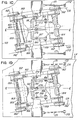
- Figure 6 is a plan view of certain control devices adapted for use with various forms of truck steering arms, such as those shown in Figures lA to 1D and 2 to 5;
- Figure 7 is a sectional view of one of the control devices of Figure 6; and
- Figure 8 is a force diagram illustrating the action of the devices shown in Figures 6 and 7.
- The structure of the truck shown in Figures lA to 1D and 2 to 5 is described below with particular reference to Figures lA, 2, 3, 4 and 5; and the steering action is thereafter described with particular reference to Figures lA, 1B, 1C and 1D.
- . In connection with the general arrangement or structure of the truck, it is first pointed out that the truck shown utilizes a truck structure incorporating two axled wheelsets, each of which is provided with a steering arm in accordance with the general principles fully described in Canadian Patent No. 1,156,093, issued November 1, 1983 and corresponding U.S.A. patent 4,455,946, issued June 26, 1984. The truck also incorporates linkage interrelating lateral motions of the vehicle body to the steering action of the wheelsets. The invention contemplates an interrelation between the lateral motion of the vehicle body and the steering motion of the wheelsets in the following manner. Thus, when travelling on straight or tangent track, if the vehicle tends to hunt or oscillate, as sometimes occurs, particularly at high speeds, the resultant lateral motion itself of the body of the vehicle is utilized, through the use of interconnecting linkage or tow bar mechanism, to introduce corrective steering action between the intercoupled wheelsets. The steering action introduced as a result of hunting of the vehicle body tends to counteract or diminish the hunting, whether this occurs at either low or high speed or on curved or tangent track.
- 5) is operating on a curved trackway above the speed at which the centrifugal force is balanced by the banking of the track (Balance Speed), the vehicle body tends to move outwardly of the curve, and the linkage or tow bar mechanism automatically provides for diminution of the self-steering action of the wheelsets and the interconnected steering arms. When the vehicle is travelling on a curved rail path below the Balance Speed, the laterally inward movement of the vehicle tends to increase the steering action. These actions of the truck, both on straight track and on curved track, are further explained with reference to Figures lA to 1D after description of the structure of that truck, in connection with Figures lA, 2, 3, 4 and 5, as follows.
- In the truck shown, the axles are indicated at 160 and 161, each axle having a pair of flanged
wheels 162 adapted to ride on rails such as indicated at R in Figure 2. The vehicle body is indicated at VB in Figure 4. In Figure lA, the diagrammatic indication of the rails at SR indicates a portion of trackway having straight rails. - Each wheelset is provided with a steering arm, these arms being indicated at 163 and 164, each steering arm carrying bearing adapters cooperating with the respective wheelsets in the manner described in the Canadian patent above identified. The truck further includes
side frames resilient pad 167 is located between the steering arm and the end of eachside frame members - The side frames also have centrally located
pads 168 which receive load from the vehicle body through the bolster indicated at 169. The bolster, in turn, receives the load of the vehicle body through main suspension springs of known type indicated at 170. The position of the bolster with relation to the car body is maintained by thedrag links 171, these links being flexibly joined to the vehicle body as indicated at 172. - With the arrangement of the major truck components, the bolster and the vehicle body in the manner described above, the bolster does not yaw relative to the vehicle body, but flexibility is permitted to accommodate lateral motions originating with lateral forces. Lateral motion between the truck side frames and the bolster is limited or controlled by a
link 173 which is pivoted at 174 (see Figures lA, 2 and 5) to theside frame 165 and which is pivoted at 175 with the bolster. - The major components of the truck structure briefly described above conform with generally known types of truck construction, and many specific parts of such structures are also described in the patents above identified.
- Turning now to the steering functions of the truck, it-is first pointed out that the steering arms are interconnected substantially midway between the axled wheelsets by means of a joint indicated generally at 176 (see particularly Figures 3 and 5). This joint includes a
pivot pin 177 and spherical ball andsocket elements resilient element 180. Therefore, the steering arm interconnection provides not only for pivotal motion of the steering arms with respect to each other about the axis of thepin 177, but also provides for-angular shift of one of the wheelsets in a vertical plane with respect to the position of the other wheelset. - The steering arms and the interconnection thereof are provided in order to insure coordinated substantially equal and opposite yawing movement of the steering arms and thus also of the wheelsets under the influence of the self-steering forces.
- Attention is now directed to the arrangement of the linkage interconnecting the steering arms and the vehicle body, in order to influence the self-steering action of 'the wheelsets when travelling on curved trackway and, in addition, when the vehicle body moves laterally relative to the truck framing.
- The linkages employed, as shown in Figures lA to 5, include linkage parts serving the same fundamental functions as the linkage parts including tow bar 48 and associated mechanism, as described with reference to the embodiment shown in Figures 5 to 12 of the Canadian patent above identified. However, the linkage now to be described is a multiple linkage, instead of a single link, as in the prior patents, and this multiple linkage arrangement is adapted for use in various truck embodiments where clearance problems would be encountered if only a single tow bar link was employed.
- In the following description of the multiple linkage arrangement herein illustrated, particular attention is directed to Figures lA, 2, 4 and 5. A lateral or double-ended
lever 181 is centrally pivoted as.indicated at 182 on thesteering arm 163, thispivot 182 being spaced between the joint 176 between the two steering arms and theaxle 160 of the outboard wheelset. Alink 183 interconnects one end of thelateral lever 181 with abracket 184 secured to and depending from the vehicle body VB, spherical pivot joints being provided at both ends of thelink 183 to accommodate various motions of the connected parts. Similarly, the other end of thelateral lever 181 is connected by alink 185, with abracket 186 secured to and depending from the vehicle body VB. Pivot or flexible joints are again provided at the ends of thelink 185. - A
reference link 187 is provided between thelink 185 and the bolster 169. As best seen in Figures lA and 5, the reference link is pivotally connected at one end with thelink 185 and pivotally connected at its other end with abracket 188 adapted to be mounted on the underside of the bolster 169. The ends of thelink 187 are desirably flexibly and pivotally connected with thelink 185 and thebracket 188, and in certain embodiments, it is provided with several alternative positions for adjustment of its longitudinal position of thelink 187 with respect to thelink 185 and thebracket 188. For this latter purpose, several different fastening apertures are provided in thebracket 188 and in thelink 185, as clearly illustrated in Figures lA and 5. This permits adjustment of the influence of lateral vehicle body motion on the steering action of the interconnected wheelsets. -
Pivoted links 189 between thesteering arm 163 and the side frames 165 and 166 aid in maintaining appropriate interrelationships of those parts under the influence of various lateral and steering forces. - The steering action of the truck just described is illustrated in Figures 1A to 1D, and reference is first made to Figures 1A and 1B which illustrate the steering action occurring as a result of lateral movement of the vehicle body relative to the truck framing on straight track at high speeds. As seen in Figures lA and 1B, the track on which the truck is travelling comprises straight rail as indicated at SR. In Figure 1A, all of the parts of the truck, including the axled wheelsets, the steering arms and all of the linkage interconnecting the vehicle body and the steering arms, are located in the mid or neutral position, representing a stable state of travel on straight track without hunting or oscillation. All of the truck parts are thus located symmetrically with respect to the centerline of the vehicle as shown on the figure.
- In Figure 1B, the vehicle body is shown as being shifted in position as indicated by the arrow LF, thereby shifting the centerline of the vehicle upwardly in the figure as is indicated. Figure 1B thus shows the vehicle body VB shifted laterally with respect to the various truck components, including the bolster 169. Because of the presence of the
link 187 between thelink 185 and thebracket 188 which is carried on the bolster 169, this lateral motion of the vehicle body with respect to the truck parts introduces a steering motion between the axled wheelsets, so that the axled wheelsets now assume relatively angled positions, being closer together at the upper side of Figure 1B than at the lower side thereof. This results in introduction of a steering action which tends to neutralize the wheel conicity which, in turn, minimizes steering activity on straight track which otherwise could lead to hunting of the truck or car body. - Figures 1C and 1D show the activity of the steering parts when travelling on a curved trackway as indicated by the curved rails CR. In Figure 1C, the effect of the self-steering action of the wheelsets is shown in the absence of lateral displacement of the vehicle body, i.e., with the vehicle travelling at the Balance Speed. It will be seen from this figure that the curved track has set-up steering forces which have caused the wheelsets to assume substantially radial positions with respect to the curved track, the angle of the wheelsets with respect to each other representing a substantial departure from parallelism as is plainly evident from the figure.
- In Figure lD, the vehicle body has been shown shifted again in the direction indicated by the arrow LF as would occur by outward movement of the body when travelling above the Balance Speed. The effect of this is to shift the position of the steering arms in a direction to diminish the steering action. As appears in Figure 1D, the steering arms and the wheelsets are in positions representing an appreciable reduction in the angle between the wheelsets.
- It will thus be seen that the linkage serves to influence the steering action and also serves as tow bar linkage. It is also to be understood that separate linkages serving the steering and tow bar functions may be employed.
- Figures 6, 7 and 8 illustrate various aspects of still another steering control mechanism. Only certain parts are shown in these figures, but it is to be understood that the arrangement is to be employed in association with other truck features, for instance, the linkages and various parts included in Figures lA to 5. The arrangement of Figures 6, 7 and 8 may be used with a variety of truck arrangements having steering arms for the wheelsets, whether or not tow bar mechanism is incorporated in the truck.
- In general, what is included in Figures 6, 7 and 8 comprises a special form of mechanism adapted to resist relative deflection of the steering arms of the truck. In various of the embodiments described in the patents above identified, and also in Figures lA to 5, resilient pads are employed between the steering arms and the side frames of the truck, such pads being indicated by the numeral 167 in Figure 1A and other figures. Those resilient pads yieldingly resist or oppose relative deflection of the steering arms and serve to exert a force tending to return the steering arms to the positions in which the wheelsets are parallel to each other.
- It has been found that it is desirable to employ in combination with such resilient pads some additional means for resisting relative deflection of the steering arms; and a mechanism for this purpose is illustrated in Figures 6, 7 and 8. This means provides non-linear restraint of interaxle and truck frame yaw motions.
- In Figures 6 and 7, the steering arms are indicated at 163 and 164 and the steering arm interconnecting joint is indicated at 176 (these reference numerals being the same as used in Figures 1A to 5).
- A pair of devices generally indicated at 190 are employed, one of these devices being shown in section in Figure 7. Each of these devices comprises a
cylindrical spring casing 191 in which ahelical compression spring 192 is arranged, the spring reacting between one end of thecasing 191 and acup 194. Thecylindrical cup 194 is positioned within the spring and has aflange 195 against which the spring reacts, urging thecup flange 195 against theadjustable stop 193. Aplunger 196 extends into thecup 194 and is adjustably associated with arod 197 by means of a threadeddevice 198. At the other end-of the system, arod 199 is connected with the base end of thecylinder 191 and the tworods arms pivot 200 carried by a fitting 201 which is fastened to the respective steering arms. A resilient device, such as arubber sleeve 202, serves as the interconnecting element between the associated rod and itspivot 200. Theresilient sleeves 202 are capable of deflection and are intended to contribute the relatively high resistance to the initial deflection of the steering arms from the parallel axle position in the manner explained more fully below with reference to Figure 8. - The
spring 192 is preloaded or precompressed between the base of thecylinder 191 and theflange 195 of thecup 194. Theplunger 196 is separable from thecup 194 but is positioned in engagement with the base of the cup in the condition shown in Figure 7. The length of the assembly shown by Figure 7 is adjusted by the threaded connection betweenparts sleeves 202 are brought approximately to point A in Figure 8 when the axles are parallel. When the steering arms are separated at the side thereof to which therespective device 190 is located, the load in thebushing 202 is reduced and will ultimately become zero, and theplunger 196 will be partially withdrawn from thecup 194. An air cylinder under a preset pressure may alternatively be used in place of thespring 192. - When the steering arms deflect toward each other at one side, the deflection-resisting device at that side comes into action to resist the deflection. Because of the presence of the resilient or
rubber sleeves 202, the initial portion of the deflection builds up to a substantial value very rapidly even with a relatively small amount of deflection. When the load exceeds the preload inspring 192, it will be compressed to a shorter length than shown, with a more gradual increase in the resistance than would otherwise be required to obtain the same deflection insleeves 202. - The combined use of both the
resilient sleeves 202 and thepreloaded spring 192 results in a pattern of resistance to steering arm deflection which is generally diagrammed in the graph of Figure 8. The total range of deflection of theresilient sleeves 202 is relatively small, as compared with the total range of deflection provided by thehelical spring 192, but the rate of increase of resistance contributed by theresilient sleeves 202 is relatively high per unit of deflection; and the rate of increase of resistance contributed by thespring 192 is relatively low per unit of deflection. This net result is indicated in the graph of Figure 8. It should be noted that the stiffness ofpads 167 between the steering arms and the axle bearings (see Figure lA) will cause an additional change in resistance with deflection. This has the effect of introducing a slope to the base line of the graph of Figure 8. - In the normal position of the parts for small angular motion of the axles, the-end of the
plunger 196 will exert a nominal force on the base of thecup 194, and only theresilient sleeves 202 will be active. - The high rate of increase of resistance in the initial portion of the deflection is important in providing high speed steering stability on straight track and in gradual curves. The change to a lesser rate of increase for large deflections prevents wheel/rail flange force and the forces within the truck assembly from becoming excessive in sharp curves.
- With respect to the embodiment described above with reference to Figures 1 to 8, particular attention is directed to the mechanism or devices provided for the purpose of yieldingly resisting yawing motions of the steering arms and thus of the wheelsets with respect to the truck framing.
- In the embodiment illustrated, a combination of several devices is employed for this purpose, including the
resilient pads 167, see Figures lA and 4, and the devices particularly shown in Figures 6 and 7. Thepads 167 resist yawing motion of the steering arms and of the wheelsets by reaction against the truck framing; and the devices of Figures 6 and 7, particularly theresilient sleeves 202 and the spring-loadeddevices 190, react between the two steeringarms - Not all of the devices shown in the drawings would necessarily be employed in all embodiments, but in the practice of the invention, it is contemplated that at least two yaw motion resisting devices should be included in the mechanism for yieldingly resisting the yawing motions of the steering arms and the wheelsets. It is contemplated that at least one of said devices, for instance the
sleeves 202, provides a relatively high rate of increase of resistance per unit of deflection in the initial portion of the yaw motion. The practice of the invention also contemplates use of another device, for instance the spring-loadeddevices 190, providing a relatively low rate of increase of resistance per unit of deflection in a portion of the motion beyond said initial portion. - The
resilient pads 167 also provide a resistance to deflection, and depending upon the pad material used and the construction and arrangement of the pads, the pads may serve as a device to resist yaw motion at either a high or low rate of increase of resistance. - 7 has been illustrated in a form reacting between the steering arms, rather than between the steering arms and the truck framing, it is to be understood that mechanisms of the type shown in Figures 6 and 7 may be provided in a manner extended from a steering arm to a portion of the truck framing. Whether the mechanisms of Figures 6 and 7 are used in a manner to react between the steering arms (as is shown in Figures 6 and 7) or are used to react between one or both of the steering arms and the truck framing, the action is essentially the same, i.e., the resistance to yawing motion of the steering arms and thus of the wheelsets is yieldingly resisted in a manner providing a relatively high rate of increase of resistance in the initial portion of the deflection, as compared with a subsequent portion of the deflection.
- This is an important factor in establishing maximum effectiveness of the steering action on curved track and in minimizing undesirable hunting and other forces on straight track.
- It will be understood that whether the yaw-resisting mechanism includes means reacting between the steering arms and the truck framing, or means reacting between the steering arms only, the yaw resistance is effective against the conjoint yawing provided by the interconnection of the steering arms. Slight yielding accommodation of yawing forces as between the two steering arms may also be accommodated by the employment of a. flexible component or arrangement, such as the
resilient element 180 shown as embodied in the steering arm interconnection joint of Figure 3.
Claims (7)
Applications Claiming Priority (2)
| Application Number | Priority Date | Filing Date | Title |
|---|---|---|---|
| US06/623,189 US4655143A (en) | 1974-01-31 | 1984-06-21 | Articulated trucks |
| US623189 | 1984-06-21 |
Publications (3)
| Publication Number | Publication Date |
|---|---|
| EP0165752A2 true EP0165752A2 (en) | 1985-12-27 |
| EP0165752A3 EP0165752A3 (en) | 1987-01-21 |
| EP0165752B1 EP0165752B1 (en) | 1990-09-12 |
Family
ID=24497117
Family Applications (1)
| Application Number | Title | Priority Date | Filing Date |
|---|---|---|---|
| EP85304082A Expired - Lifetime EP0165752B1 (en) | 1984-06-21 | 1985-06-10 | Self-steering trucks |
Country Status (7)
| Country | Link |
|---|---|
| US (1) | US4655143A (en) |
| EP (1) | EP0165752B1 (en) |
| JP (1) | JPH0647380B2 (en) |
| AU (1) | AU572305B2 (en) |
| CA (1) | CA1251096A (en) |
| DE (1) | DE3579633D1 (en) |
| IN (1) | IN165100B (en) |
Cited By (7)
| Publication number | Priority date | Publication date | Assignee | Title |
|---|---|---|---|---|
| WO1988000543A1 (en) * | 1986-07-11 | 1988-01-28 | Sig Schweizerische Industrie-Gesellschaft | Mechanical device for stabilizing rail vehicles |
| EP0313188A2 (en) * | 1987-07-28 | 1989-04-26 | Utdc Inc. | Longitudinal steering linkage for truck with interaxle yokes |
| FR2632917A1 (en) * | 1988-06-17 | 1989-12-22 | Durand Charles | Method and device for improving the stability and behaviour of a railway bogie in a bend, and bogie equipped with such a device |
| US5123358A (en) * | 1989-05-24 | 1992-06-23 | Rautaruukki Oy | Bogie construction of a railway car |
| AT404010B (en) * | 1994-06-09 | 1998-07-27 | Waagner Biro Ag | Truck, in particular pivoted bogie for a rail vehicle such as the wagon of a funicular railway |
| EP0930210A1 (en) * | 1998-01-14 | 1999-07-21 | SLM Schweizerische Lokomotiv- und Maschinenfabrik AG | Running gear for railway vehicles and railway vehicle with at least one such running gear |
| WO2005032904A1 (en) * | 2003-09-10 | 2005-04-14 | Db Fernverkehr Ag | Coupling of hunting dampers to vehicles with a tilting body |
Families Citing this family (12)
| Publication number | Priority date | Publication date | Assignee | Title |
|---|---|---|---|---|
| US4922832A (en) * | 1988-01-22 | 1990-05-08 | Strick Corporation | Intermodal road/rail transportation system |
| US4955144A (en) * | 1988-01-22 | 1990-09-11 | Strick Corporation | Compatible intermodal road/rail transportation system |
| US5009521A (en) * | 1989-07-14 | 1991-04-23 | A. Stucki Company Division Of Hansen, Inc. | Railway truck and bearing adapter therefor, and method for controlling relative motion between truck components |
| CA2019520C (en) * | 1989-07-14 | 1995-10-03 | Donald Wiebe | Railway truck and bearing adapter therefor, and method for controlling relative motion between truck components |
| US5237933A (en) * | 1991-07-25 | 1993-08-24 | Lord Corporation | Service-life, low-profile, retrofittable, elastomeric mounting for three-piece, railroad-car trucks |
| US5224428A (en) * | 1991-10-31 | 1993-07-06 | Wronkiewicz Robert D | Strengthened structure for a steering arm assembly having a compound radial fillet at juncture |
| KR100614610B1 (en) | 2004-12-30 | 2006-08-21 | 한국철도기술연구원 | The railway vehicle bogie for having to shock-absorbing function of front and rear direction |
| US7665622B2 (en) * | 2005-12-15 | 2010-02-23 | Standard Car Truck Company | Railroad car coupler centering device |
| JP5010629B2 (en) * | 2009-02-20 | 2012-08-29 | 三菱重工業株式会社 | Low floor vehicle |
| JP5010628B2 (en) * | 2009-02-20 | 2012-08-29 | 三菱重工業株式会社 | Low floor vehicle |
| US10293839B2 (en) * | 2015-12-03 | 2019-05-21 | Amsted Rail Company, Inc. | Railway car truck with friction damping |
| WO2022077077A1 (en) * | 2020-10-14 | 2022-04-21 | Rodrigues De Lima Neto Manoel | Passive radial railway bogie using mobile side frames, rollers and roller tracks, and wheelsets with freewheel |
Citations (6)
| Publication number | Priority date | Publication date | Assignee | Title |
|---|---|---|---|---|
| DE2659797A1 (en) * | 1972-11-10 | 1977-08-11 | South African Inventions | CHASSIS FOR A RAIL VEHICLE |
| DE2940892A1 (en) * | 1978-10-05 | 1980-07-03 | Dresser Ind | METHOD FOR CONVERTING A RAILWAY CHASSIS WITH A MECHANISM FOR WHEEL SET CONTROL |
| DE2911105A1 (en) * | 1978-03-27 | 1980-09-25 | Canadair Ltd | CHASSIS FOR A RAIL VEHICLE |
| EP0031720A2 (en) * | 1979-12-31 | 1981-07-08 | AMSTED Industries Incorporated | Railroad car bogie |
| DE3235692A1 (en) * | 1981-09-28 | 1983-04-14 | The Budd Co., 48084 Troy, Mich. | FORCE-CONTROLLABLE BOGE FOR A RAILWAY TROLLEY |
| US4428301A (en) * | 1981-08-03 | 1984-01-31 | Lukens General Industries, Inc. | Radial axle railway truck |
Family Cites Families (33)
| Publication number | Priority date | Publication date | Assignee | Title |
|---|---|---|---|---|
| US502503A (en) * | 1893-08-01 | Henry f | ||
| CA642321A (en) * | 1962-06-05 | L. Lich Richard | Railway vehicle trucks | |
| CA799724A (en) * | 1968-11-26 | R. Cripe Alan | Railway truck assembly | |
| CA698023A (en) * | 1964-11-17 | K. Dickey Donald | Railway vehicle suspension | |
| US33167A (en) * | 1861-08-27 | Improvement in railroad-car trucks | ||
| US243797A (en) * | 1881-07-05 | Car-truck | ||
| US555857A (en) * | 1896-03-03 | Island | ||
| US220928A (en) * | 1879-10-28 | Improvement in car-trucks | ||
| US1707046A (en) * | 1925-11-07 | 1929-03-26 | Boyden Railroad Car Truck Corp | Semisquare railroad-car truck |
| US1640179A (en) * | 1926-03-04 | 1927-08-23 | Timken Roller Bearing Co | Railway-car truck |
| FR678696A (en) * | 1928-07-27 | 1930-04-03 | Wagon Fabrik A G | Running gear for vehicles having at least four axles |
| US1744986A (en) * | 1928-10-24 | 1930-01-28 | Richards David Rees | Car truck |
| GB363558A (en) * | 1929-09-10 | 1931-12-24 | Sueddeutsche Eisenbahn-Gesellschaft | |
| US2296106A (en) * | 1940-04-08 | 1942-09-15 | Holland Co | Radial truck |
| US2360061A (en) * | 1942-12-01 | 1944-10-10 | Pennsylvania Railroad Co | Railway car truck |
| US3274955A (en) * | 1963-09-03 | 1966-09-27 | Lord Corp | Resilient roller bearing adapter |
| GB1179723A (en) * | 1967-02-03 | 1970-01-28 | British Railways Board | Improvements in or relating to Railway Vehicles and Bogies |
| US4131069A (en) * | 1967-11-02 | 1978-12-26 | Railway Engineering Associates, Inc. | Articulated railway car trucks |
| GB1261896A (en) * | 1968-09-17 | 1972-01-26 | British Railways Board | Improvements in or relating to railway vehicles |
| US3948188A (en) * | 1970-06-05 | 1976-04-06 | Swiss Aluminium Ltd. | Resilient railway bogie |
| US3782294A (en) * | 1971-08-05 | 1974-01-01 | Rockwell International Corp | Articulated railway truck swinging bolster |
| US3789770A (en) * | 1972-02-02 | 1974-02-05 | Railway Eng Ass Inc | Articulated railway truck |
| US3817188A (en) * | 1972-09-12 | 1974-06-18 | Gen Steel Ind Inc | Railway trucks with pivotally connected side frames |
| US4067261A (en) * | 1972-11-10 | 1978-01-10 | South African Inventions Development Corporation | Damping railway vehicle suspension |
| US3862606A (en) * | 1973-06-29 | 1975-01-28 | Brian T Scales | Radial truck |
| US4003316A (en) * | 1973-10-23 | 1977-01-18 | Monselle Dale E | Articulated railway car trucks |
| SE393071B (en) * | 1974-04-05 | 1977-05-02 | South African Inventions | RAILWAY TROLLEY |
| US4134343A (en) * | 1976-09-27 | 1979-01-16 | General Steel Industries, Inc. | Radial axle railway truck |
| US4147237A (en) * | 1977-08-15 | 1979-04-03 | Amsted Industries Incorporated | Braking system and method for railroad truck |
| US4356775A (en) * | 1978-01-18 | 1982-11-02 | H. Neil Paton | Damped railway car suspension |
| US4458604A (en) * | 1978-05-19 | 1984-07-10 | Dresser Industries, Inc. | Radial railway truck |
| JPS55148648A (en) * | 1979-05-04 | 1980-11-19 | Canadair Ltd | Railway truck assembled body |
| JPS58183344A (en) * | 1982-04-21 | 1983-10-26 | 株式会社日立製作所 | Four wheel truck for railway rolling stock |
-
1984
- 1984-06-21 US US06/623,189 patent/US4655143A/en not_active Expired - Lifetime
-
1985
- 1985-06-06 CA CA000483289A patent/CA1251096A/en not_active Expired
- 1985-06-10 DE DE8585304082T patent/DE3579633D1/en not_active Expired - Fee Related
- 1985-06-10 EP EP85304082A patent/EP0165752B1/en not_active Expired - Lifetime
- 1985-06-19 AU AU43824/85A patent/AU572305B2/en not_active Ceased
- 1985-06-19 IN IN456/MAS/85A patent/IN165100B/en unknown
- 1985-06-20 JP JP60133147A patent/JPH0647380B2/en not_active Expired - Lifetime
Patent Citations (6)
| Publication number | Priority date | Publication date | Assignee | Title |
|---|---|---|---|---|
| DE2659797A1 (en) * | 1972-11-10 | 1977-08-11 | South African Inventions | CHASSIS FOR A RAIL VEHICLE |
| DE2911105A1 (en) * | 1978-03-27 | 1980-09-25 | Canadair Ltd | CHASSIS FOR A RAIL VEHICLE |
| DE2940892A1 (en) * | 1978-10-05 | 1980-07-03 | Dresser Ind | METHOD FOR CONVERTING A RAILWAY CHASSIS WITH A MECHANISM FOR WHEEL SET CONTROL |
| EP0031720A2 (en) * | 1979-12-31 | 1981-07-08 | AMSTED Industries Incorporated | Railroad car bogie |
| US4428301A (en) * | 1981-08-03 | 1984-01-31 | Lukens General Industries, Inc. | Radial axle railway truck |
| DE3235692A1 (en) * | 1981-09-28 | 1983-04-14 | The Budd Co., 48084 Troy, Mich. | FORCE-CONTROLLABLE BOGE FOR A RAILWAY TROLLEY |
Cited By (12)
| Publication number | Priority date | Publication date | Assignee | Title |
|---|---|---|---|---|
| WO1988000543A1 (en) * | 1986-07-11 | 1988-01-28 | Sig Schweizerische Industrie-Gesellschaft | Mechanical device for stabilizing rail vehicles |
| FR2603012A1 (en) * | 1986-07-11 | 1988-02-26 | Sig Schweiz Industrieges | MECHANICAL CONTROL DEVICE INSTALLED IN RAIL VEHICLES |
| EP0388999A3 (en) * | 1986-07-11 | 1991-04-10 | SIG Schweizerische Industrie-Gesellschaft | Mechanical device for supporting railway vehicles |
| CH680996A5 (en) * | 1986-07-11 | 1992-12-31 | Sig Schweiz Industrieges | |
| EP0313188A2 (en) * | 1987-07-28 | 1989-04-26 | Utdc Inc. | Longitudinal steering linkage for truck with interaxle yokes |
| EP0313188A3 (en) * | 1987-07-28 | 1989-11-29 | Utdc Inc. | Longitudinal steering linkage for truck with interaxle yokes |
| AU609502B2 (en) * | 1987-07-28 | 1991-05-02 | Utdc Inc. | Longitudinal steering linkage for truck with interaxle yokes |
| FR2632917A1 (en) * | 1988-06-17 | 1989-12-22 | Durand Charles | Method and device for improving the stability and behaviour of a railway bogie in a bend, and bogie equipped with such a device |
| US5123358A (en) * | 1989-05-24 | 1992-06-23 | Rautaruukki Oy | Bogie construction of a railway car |
| AT404010B (en) * | 1994-06-09 | 1998-07-27 | Waagner Biro Ag | Truck, in particular pivoted bogie for a rail vehicle such as the wagon of a funicular railway |
| EP0930210A1 (en) * | 1998-01-14 | 1999-07-21 | SLM Schweizerische Lokomotiv- und Maschinenfabrik AG | Running gear for railway vehicles and railway vehicle with at least one such running gear |
| WO2005032904A1 (en) * | 2003-09-10 | 2005-04-14 | Db Fernverkehr Ag | Coupling of hunting dampers to vehicles with a tilting body |
Also Published As
| Publication number | Publication date |
|---|---|
| DE3579633D1 (en) | 1990-10-18 |
| CA1251096A (en) | 1989-03-14 |
| US4655143A (en) | 1987-04-07 |
| EP0165752A3 (en) | 1987-01-21 |
| JPH0647380B2 (en) | 1994-06-22 |
| IN165100B (en) | 1989-08-19 |
| JPS6175053A (en) | 1986-04-17 |
| EP0165752B1 (en) | 1990-09-12 |
| AU4382485A (en) | 1986-01-02 |
| AU572305B2 (en) | 1988-05-05 |
Similar Documents
| Publication | Publication Date | Title |
|---|---|---|
| EP0165752B1 (en) | Self-steering trucks | |
| US4480553A (en) | Stabilized railway vehicle | |
| US4067261A (en) | Damping railway vehicle suspension | |
| US4134343A (en) | Radial axle railway truck | |
| EP0258502B1 (en) | Self-steering railway truck | |
| CA1185831A (en) | Flexible railway car truck | |
| US4131069A (en) | Articulated railway car trucks | |
| US4356775A (en) | Damped railway car suspension | |
| US4679506A (en) | Railway truck with improved steering linkage, detachable suspension and traction motor mounted brake | |
| JPH021168Y2 (en) | ||
| US5174218A (en) | Self-steering trucks with side bearings supporting the entire weight of the vehicle | |
| US5918547A (en) | Roller bearing adapter stabilizer bar | |
| US5000097A (en) | Self-steering railway truck | |
| US5377597A (en) | Rail vehicle having articulated connection between vehicle bodies for prohibiting telescoping in case of accidents | |
| US4996928A (en) | Integrated chassis and suspension systems for monorail vehicles | |
| CA1148029A (en) | Bolsterless bogie with air-spring suspension for rail vehicles | |
| JPS6344590B2 (en) | ||
| US3547046A (en) | Railway locomotive truck with low traction point | |
| US4841873A (en) | Railway locomotive and stabilized self steering truck therefor | |
| KR860000278B1 (en) | Bogie truck for railroad car | |
| US5351624A (en) | Bogie for high-speed rail vehicles | |
| JPH0571428B2 (en) | ||
| US4706571A (en) | Self-steering trucks | |
| CA1189390A (en) | Articulated truck assembly | |
| US4781124A (en) | Articulated trucks |
Legal Events
| Date | Code | Title | Description |
|---|---|---|---|
| PUAI | Public reference made under article 153(3) epc to a published international application that has entered the european phase |
Free format text: ORIGINAL CODE: 0009012 |
|
| AK | Designated contracting states |
Designated state(s): CH DE FR GB LI |
|
| PUAL | Search report despatched |
Free format text: ORIGINAL CODE: 0009013 |
|
| AK | Designated contracting states |
Kind code of ref document: A3 Designated state(s): CH DE FR GB LI |
|
| 17P | Request for examination filed |
Effective date: 19870714 |
|
| 17Q | First examination report despatched |
Effective date: 19890222 |
|
| GRAA | (expected) grant |
Free format text: ORIGINAL CODE: 0009210 |
|
| AK | Designated contracting states |
Kind code of ref document: B1 Designated state(s): CH DE FR GB LI |
|
| REF | Corresponds to: |
Ref document number: 3579633 Country of ref document: DE Date of ref document: 19901018 |
|
| ET | Fr: translation filed | ||
| PLBE | No opposition filed within time limit |
Free format text: ORIGINAL CODE: 0009261 |
|
| STAA | Information on the status of an ep patent application or granted ep patent |
Free format text: STATUS: NO OPPOSITION FILED WITHIN TIME LIMIT |
|
| 26N | No opposition filed | ||
| PGFP | Annual fee paid to national office [announced via postgrant information from national office to epo] |
Ref country code: GB Payment date: 19960603 Year of fee payment: 12 |
|
| PGFP | Annual fee paid to national office [announced via postgrant information from national office to epo] |
Ref country code: FR Payment date: 19960611 Year of fee payment: 12 |
|
| PGFP | Annual fee paid to national office [announced via postgrant information from national office to epo] |
Ref country code: DE Payment date: 19960612 Year of fee payment: 12 |
|
| PGFP | Annual fee paid to national office [announced via postgrant information from national office to epo] |
Ref country code: CH Payment date: 19960620 Year of fee payment: 12 |
|
| PG25 | Lapsed in a contracting state [announced via postgrant information from national office to epo] |
Ref country code: GB Free format text: LAPSE BECAUSE OF NON-PAYMENT OF DUE FEES Effective date: 19970610 |
|
| PG25 | Lapsed in a contracting state [announced via postgrant information from national office to epo] |
Ref country code: LI Free format text: LAPSE BECAUSE OF NON-PAYMENT OF DUE FEES Effective date: 19970630 Ref country code: CH Free format text: LAPSE BECAUSE OF NON-PAYMENT OF DUE FEES Effective date: 19970630 |
|
| GBPC | Gb: european patent ceased through non-payment of renewal fee |
Effective date: 19970610 |
|
| REG | Reference to a national code |
Ref country code: CH Ref legal event code: PL |
|
| PG25 | Lapsed in a contracting state [announced via postgrant information from national office to epo] |
Ref country code: FR Free format text: LAPSE BECAUSE OF NON-PAYMENT OF DUE FEES Effective date: 19980227 |
|
| PG25 | Lapsed in a contracting state [announced via postgrant information from national office to epo] |
Ref country code: DE Free format text: LAPSE BECAUSE OF NON-PAYMENT OF DUE FEES Effective date: 19980303 |
|
| REG | Reference to a national code |
Ref country code: FR Ref legal event code: ST |
|
| REG | Reference to a national code |
Ref country code: FR Ref legal event code: ST |