EP0165643A2 - Elektrothermale Atomisierungsvorrichtung - Google Patents
Elektrothermale Atomisierungsvorrichtung Download PDFInfo
- Publication number
- EP0165643A2 EP0165643A2 EP85200958A EP85200958A EP0165643A2 EP 0165643 A2 EP0165643 A2 EP 0165643A2 EP 85200958 A EP85200958 A EP 85200958A EP 85200958 A EP85200958 A EP 85200958A EP 0165643 A2 EP0165643 A2 EP 0165643A2
- Authority
- EP
- European Patent Office
- Prior art keywords
- probe
- sample
- atomiser
- cuvette
- hollow body
- Prior art date
- Legal status (The legal status is an assumption and is not a legal conclusion. Google has not performed a legal analysis and makes no representation as to the accuracy of the status listed.)
- Withdrawn
Links
Images

Classifications
-
- G—PHYSICS
- G01—MEASURING; TESTING
- G01N—INVESTIGATING OR ANALYSING MATERIALS BY DETERMINING THEIR CHEMICAL OR PHYSICAL PROPERTIES
- G01N21/00—Investigating or analysing materials by the use of optical means, i.e. using sub-millimetre waves, infrared, visible or ultraviolet light
- G01N21/62—Systems in which the material investigated is excited whereby it emits light or causes a change in wavelength of the incident light
- G01N21/71—Systems in which the material investigated is excited whereby it emits light or causes a change in wavelength of the incident light thermally excited
- G01N21/74—Systems in which the material investigated is excited whereby it emits light or causes a change in wavelength of the incident light thermally excited using flameless atomising, e.g. graphite furnaces
Definitions
- the invention relates to an electrothermal atomiser for a spectrophotometer said atomiser comprising a hollow body of electrically conductive material, means for depositing a sample on a probe, means for inserting the probe into the interior of the hollow body, and means for passing an electrical current through , the hollow body to heat the interior of the hollow body to a temperature which is sufficient to atomise the sample.
- Such an atomiser is disclosed in UK Patent Application No. 2136144A.
- the probe was formed of pyrolytic graphite as was the preferred form of hollow body (or cuvette).
- An atomiser as set forth in the opening paragraph has also been disclosed in UK Patent Application No. 2088582A in which the probe (or sample carrier) is formed of graphite of unspecified type.
- UK Patent Application No. 2071845 discloses such an atomiser in which the probe is in the form of a wire (tungsten) filament.
- UK Patent Application No. 2113128A discloses a probe made from glassy carbon.
- probes made from pyrolytic graphite and glassy carbon and probes coated with pyrolytic graphite suffer from the disadvantage of sample spreading when samples contain more than about 0.5% v/v of nitric acid.
- the reduced surface tension of such solutions causes the sample to spread irreproducibly up the probe stem during the drying phase.
- Various proposals have been made in an attempt to overcome this problem. The initial experiments were conducted with the probe inserted into the cuvette through a slot in the wall in a manner as described in UK Patent Application No. 2136144A. With this configuration only the probe head is heated significantly during the drying phase, while the stem, outside the cuvette, remains cool. It was thought that the sharp temperature gradient along the probe could be responsible for the spreading phenomenon, as the liquid sample would tend to travel to the cooler region outside the cuvette.
- the 'end entry' probe allows the probe to enter the cuvette parallel to its long axis. It is therefore no longer necessary to cut a slot in the cuvette, and so improved cuvette lifetimes and sensitivity would be expected.
- the temperature gradient along the probe would now also be much less steep, as a large part of the stem as well as the head would be heated. It was throught that the spreading problem would therefore be alleviated, and that even if some spreading did occur, as much more of the probe stem would be introduced into the hot zone during the atomisation phase, the effects might be less significant.
- the invention provides an electrothermal atomiser as set forth in the opening paragraph characterised in that at least the portion of the probe on which the sample is to be deposited is formed from electrographite.
- the portion of the probe on which the sample is to be deposited may comprise a recess for containing the sample. This reduces the spreading problems involved with samples such as organic solvents or body fluids containing surfactants.
- the probe may comprise a head portion for receiving the sample and a stem portion, a step being formed between the head and stem portions. This helps to reduce spreading of the sample up the probe stem but suffers from the disadvantage that a double measurement peak is obtained. This is caused by part of the sample running back against the step and drying in the corner while part remains on the probe head. The temperature of the step region lags behind that of the head as it has a greater mass so that the samples in the two areas will be atomised at different times producing the double peaks.
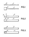
- the probe comprises a stem portion 1 and a flat head portion 2.
- At least the head portion 2 is formed from electrographite, a suitable grade of which is that sold by Ringsdorff G.m.b.H of Bonn-Badgodesberg, West Germany under the reference RWO.
- the whole probe may be formed from a single piece of electrographite.
- the stem may be formed from a material having a lower thermal conductivity which has the advantage of increasing the speed of heating of the head portion as a smaller amount of heat is conducted along the stem.
- Figure 2 shows an alternative form of probe which comprises a stem portion 1 and a head portion 2.
- the stem portion 1 is relatively thick so that it forms a step 3 between the stem and head portion. This form of probe, however, suffers from the disadvantage dicussed hereinbefore that a double measurement peak is produced.
- Figure 3 shows a further alternative form of probe which comprises a stem portion 1 and a head portion 2 which is provided with a recess or dimple 4.
- the recess 4 is provided for samples such as organic solvents or body fluids containing surfactants.
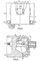
- Figures 4,5 and 6 show a cuvette 5, a probe 6, and an actuator 7 mounted in and on an atomiser for an atomic absorption spectrophotometer.
- the probe 6 takes the form of a probe as described with reference to Figures 1, 2 or 3 and the cuvette is a hollow cylindrical graphite body.
- the atomiser comprises a body 10 having a hinged door 11. Within the atomiser body 10 two contact jaws, one of which is shown at 12 grip each end of the cuvette 5. The jaws have electrical connection terminals, one of which is shown at 13, to which an electrical current source may be connected for passing a current through the cuvette.
- the contact jaw 12 comprises a fixed lower portion 14 and a pivotted upper portion 15 which can be pivotted by moving a member 16 into the body 10,horizontally to the left in the embodiment shown in Figure 6.
- the actuator 7, which in this embodiment is in the form of a solenoid but which may be, for example a motor and cam drive, is attached to the door 11 of the furnace by four screws 17 to 20 and the probe 6 passes through an aperture 21 in the door 11.
- a further aperture 22 is provided in the front of the door 11 through which a dosing tube 8 may be inserted to deposite a sample on the probe.
- the aperture 22 is closed when the cuvette is being heated so that the escape of protective gas is reduced.
- the cuvette 5 is normally made of carbon it is necessary to prevent rapid oxidation when it is heated to the atomising temperatures which may be in the region of 3000°C. Consequently it is customary to provide a flow of inert gas over and through the cuvette 5.
- the door 11 is hinged along its bottom edge, being mounted between two fixed members 23 and 24 by a shaft 25 the ends of which are free to rotate in the fixed members 23 and 24.
- the opening and closing of the door 11 is performed by a rod 26 pivotally connected to a lug 27 on the door 11 and operated by a piston in a cylinder.
- a quartz window 29 is set in both sides of the door 11, the quartz windows being aligned with the longitudinal axis of the tubular body 6.
- the door 11 is normally kept closed and only opened to replace the cuvette when it has reached the end of its life.
- a probe made of electrographite can advantageously be applied to any atomiser in which the sample is atomised off a probe.
- the particular shape of the head portion of the probe may also be adapted to suit the form of atomiser used, in particular for either front or end entry i.e. transverse or parallel to the longitudinal axis of the cuvette.
Landscapes
- Health & Medical Sciences (AREA)
- Life Sciences & Earth Sciences (AREA)
- Analytical Chemistry (AREA)
- Biochemistry (AREA)
- General Life Sciences & Earth Sciences (AREA)
- Nuclear Medicine, Radiotherapy & Molecular Imaging (AREA)
- Physics & Mathematics (AREA)
- Chemical & Material Sciences (AREA)
- Environmental & Geological Engineering (AREA)
- Geology (AREA)
- General Health & Medical Sciences (AREA)
- General Physics & Mathematics (AREA)
- Immunology (AREA)
- Pathology (AREA)
- Investigating Or Analysing Materials By Optical Means (AREA)
- Investigating, Analyzing Materials By Fluorescence Or Luminescence (AREA)
Applications Claiming Priority (2)
| Application Number | Priority Date | Filing Date | Title |
|---|---|---|---|
| GB08415682A GB2160673A (en) | 1984-06-20 | 1984-06-20 | Electrothermal atomiser |
| GB8415682 | 1984-06-20 |
Publications (2)
| Publication Number | Publication Date |
|---|---|
| EP0165643A2 true EP0165643A2 (de) | 1985-12-27 |
| EP0165643A3 EP0165643A3 (de) | 1987-08-05 |
Family
ID=10562689
Family Applications (1)
| Application Number | Title | Priority Date | Filing Date |
|---|---|---|---|
| EP85200958A Withdrawn EP0165643A3 (de) | 1984-06-20 | 1985-06-18 | Elektrothermale Atomisierungsvorrichtung |
Country Status (5)
| Country | Link |
|---|---|
| US (1) | US4639136A (de) |
| EP (1) | EP0165643A3 (de) |
| JP (1) | JPS6113141A (de) |
| AU (1) | AU4376285A (de) |
| GB (1) | GB2160673A (de) |
Cited By (3)
| Publication number | Priority date | Publication date | Assignee | Title |
|---|---|---|---|---|
| EP0226236A1 (de) * | 1985-11-12 | 1987-06-24 | Philips Electronics Uk Limited | Graphitsonde und elektrothermischer Zerstäuber mit einer solchen Sonde |
| EP0386521A1 (de) * | 1989-03-08 | 1990-09-12 | Bodenseewerk Perkin-Elmer Gmbh | Vorrichtung zum elektrothermischen Atomisieren von Proben für spektroskopische Zwecke |
| US5872013A (en) * | 1987-11-16 | 1999-02-16 | Janssen Pharmaceutica N.V. | Universally applicable detection system based on ultra small colloidal metal particles |
Families Citing this family (1)
| Publication number | Priority date | Publication date | Assignee | Title |
|---|---|---|---|---|
| DE8803144U1 (de) * | 1988-03-09 | 1988-04-21 | Ringsdorff-Werke GmbH, 5300 Bonn | Graphitrohrofen mit Probenträger für die Atomabsorptionsspektroskopie |
Family Cites Families (14)
| Publication number | Priority date | Publication date | Assignee | Title |
|---|---|---|---|---|
| DE2023336C3 (de) * | 1970-05-13 | 1974-01-24 | Bodenseewerk Perkin-Elmer & Co Gmbh, 7770 Ueberlingen | Vorrichtung für flammenlose Atomabsorptionsspektrometrie |
| US3895873A (en) * | 1974-04-04 | 1975-07-22 | Instrumentation Labor Inc | Spectroscopic analysis apparatus utilizing a tubular heating element and a passive sample holder |
| DE7825590U1 (de) * | 1978-08-29 | 1978-11-30 | Ringsdorff Werke Gmbh, 5300 Bonn | Probentraeger |
| DE2924123C2 (de) * | 1979-06-15 | 1985-04-04 | Bodenseewerk Perkin-Elmer & Co GmbH, 7770 Überlingen | Graphitrohr zum Atomisieren von Proben bei der flammenlosen Atomabsorptions-Spektroskopie |
| DE2949476A1 (de) * | 1979-12-08 | 1981-06-11 | Philips Patentverwaltung Gmbh, 2000 Hamburg | Verfahren zur herstellung von kuevetten fuer die flammenlose atom-absorptions-spektroskopie |
| DE3009794C2 (de) * | 1980-03-14 | 1983-08-04 | Bodenseewerk Perkin-Elmer & Co GmbH, 7770 Überlingen | Vorrichtung zur Probeneingabe in ein Graphitrohr bei der flammenlosen Atomabsorptions-Spektroskopie und Verfahren unter Verwendung der Vorrichtung |
| DE3044627C2 (de) * | 1980-11-27 | 1984-06-07 | Bodenseewerk Perkin-Elmer & Co GmbH, 7770 Überlingen | Vorrichtung zur Probeneingabe in ein Graphitrohr bei der flammenlosen Atomabsorptions-Spektroskopie |
| DE3140458A1 (de) * | 1981-10-12 | 1983-04-21 | Philips Patentverwaltung Gmbh, 2000 Hamburg | Atomisierungsvorrichtung fuer die atomabsorptionsspektroskopie |
| US4548497A (en) * | 1981-11-25 | 1985-10-22 | Bodenseewerk Perkin-Elmer & Co., Gmbh | Method and device for introducing a sample into a graphite tube |
| DE3208744A1 (de) * | 1982-03-11 | 1983-09-22 | Philips Patentverwaltung Gmbh, 2000 Hamburg | Rohrcuvette fuer die atomabsorptionsspektrometrie |
| DE3217417C2 (de) * | 1982-05-08 | 1984-02-09 | Bodenseewerk Perkin-Elmer & Co GmbH, 7770 Überlingen | Vorrichtung zum Atomisieren einer Probe bei der flammenlosen Atomabsorptions-Spektroskopie |
| DE3234770A1 (de) * | 1982-09-20 | 1984-03-22 | Schunk & Ebe Gmbh, 6301 Heuchelheim | Probentraeger, insbesondere graphitrohr oder graphitboot, fuer die flammenlose atom-absorptions-spektroskopie |
| GB2136144A (en) * | 1983-03-02 | 1984-09-12 | Philips Electronic Associated | Atomic spectroscopy |
| DD217026A1 (de) * | 1983-08-02 | 1985-01-02 | Elektrokohle Lichtenberg Veb | Graphitrohrkuevette fuer die flammenlose atomabsorptionsspektrometrie |
-
1984
- 1984-06-20 GB GB08415682A patent/GB2160673A/en not_active Withdrawn
-
1985
- 1985-05-28 US US06/738,003 patent/US4639136A/en not_active Expired - Fee Related
- 1985-06-17 JP JP60130060A patent/JPS6113141A/ja active Pending
- 1985-06-18 EP EP85200958A patent/EP0165643A3/de not_active Withdrawn
- 1985-06-18 AU AU43762/85A patent/AU4376285A/en not_active Abandoned
Cited By (3)
| Publication number | Priority date | Publication date | Assignee | Title |
|---|---|---|---|---|
| EP0226236A1 (de) * | 1985-11-12 | 1987-06-24 | Philips Electronics Uk Limited | Graphitsonde und elektrothermischer Zerstäuber mit einer solchen Sonde |
| US5872013A (en) * | 1987-11-16 | 1999-02-16 | Janssen Pharmaceutica N.V. | Universally applicable detection system based on ultra small colloidal metal particles |
| EP0386521A1 (de) * | 1989-03-08 | 1990-09-12 | Bodenseewerk Perkin-Elmer Gmbh | Vorrichtung zum elektrothermischen Atomisieren von Proben für spektroskopische Zwecke |
Also Published As
| Publication number | Publication date |
|---|---|
| JPS6113141A (ja) | 1986-01-21 |
| AU4376285A (en) | 1986-01-02 |
| US4639136A (en) | 1987-01-27 |
| EP0165643A3 (de) | 1987-08-05 |
| GB8415682D0 (en) | 1984-07-25 |
| GB2160673A (en) | 1985-12-24 |
Similar Documents
| Publication | Publication Date | Title |
|---|---|---|
| Slavin et al. | The L'vov platform for furnace atomic absorption analysis | |
| US4639136A (en) | Electrothermal atomiser | |
| Bulska et al. | Comparison of chemical modifiers for the determination of selenium by electrothermal atomic-absorption spectrometry | |
| US4721387A (en) | Graphite probe and electrothermal atomizer including such a probe | |
| Rettberg et al. | A temperature controlled, tantalum second surface for graphite furnace atomization | |
| DD233190A1 (de) | Atomisator fuer probentraeger | |
| Chakrabarti et al. | Atomic absorption spectrometric determination of Cd, Pb, Zn, Cu, Co and Fe in oyster tissue by direct atomization from the solid state using the graphite furnace platform technique | |
| Frech | Recent developments in atomizers for electrothermal atomic absorption spectrometry | |
| US4657389A (en) | Electrothermal atomizer | |
| Berndt et al. | Improvements in loop atomic absorption spectrometry by application of an iridium loop and a ceramic collection tube | |
| US4824241A (en) | Atomic spectroscopy | |
| Wahab et al. | Studies on the sensitivity of yttrium by electrothermal atomization from metallic and metal-carbide surfaces of a heated graphite atomizer in atomic absorption spectrometry | |
| Styris et al. | Experimental evaluation of analyte-furnace interactions using combined atomic absorption mass spectrometric techniques | |
| Goforth et al. | A graphite-tube furnace for use in laser-excited atomic-fluorescence spectrometry | |
| Helmi et al. | Interatomic potentials and the van der Waals' coefficient for the intercombination Cd 326.1 nm absorption line broadened by cadmium pressure | |
| Slaveykova et al. | Application of the Kelvin equation to vaporization of silver and gold in electrothermal atomic absorption spectrometry | |
| Mahmood et al. | Physical behaviour of nickel and copper modifiers used in the determination of selenium by electrothermal atomic absorption spectrometry | |
| Frank et al. | Optical response of cesium coated C60 | |
| EP0088475A2 (de) | Cuvette für die Atom-Absorptions-Spektrometrie | |
| Lawson et al. | Influence of furnace design on operation, sensitivity and matrix interferences in electrothermal atomic absorption spectrometry | |
| JPS5875047A (ja) | 原子吸光分光分析用アトマイザ− | |
| Ward et al. | Use of a nitrous oxide-acetylene flame to minimize interferences in microsampling-cup atomic absorption spectrometry | |
| Golovashkin | Optical Properties of Lead at Low Temperatures | |
| Gordon | The work function of sputter‐formed Re‐1% Mo | |
| Imai et al. | Effect of the surface treatment of a graphite furnace with a refractory element (hafnium, titanium, tungsten and zirconium) by a one-drop coating method on the atomization mechanism of indium in electrothermal atomic absorption spectrometry |
Legal Events
| Date | Code | Title | Description |
|---|---|---|---|
| PUAI | Public reference made under article 153(3) epc to a published international application that has entered the european phase |
Free format text: ORIGINAL CODE: 0009012 |
|
| AK | Designated contracting states |
Designated state(s): CH DE FR GB IT LI SE |
|
| PUAL | Search report despatched |
Free format text: ORIGINAL CODE: 0009013 |
|
| AK | Designated contracting states |
Kind code of ref document: A3 Designated state(s): CH DE FR GB IT LI SE |
|
| 17P | Request for examination filed |
Effective date: 19880202 |
|
| RAP3 | Party data changed (applicant data changed or rights of an application transferred) |
Owner name: N.V. PHILIPS' GLOEILAMPENFABRIEKEN Owner name: PHILIPS ELECTRONIC AND ASSOCIATED INDUSTRIES LIMIT |
|
| STAA | Information on the status of an ep patent application or granted ep patent |
Free format text: STATUS: THE APPLICATION IS DEEMED TO BE WITHDRAWN |
|
| 18D | Application deemed to be withdrawn |
Effective date: 19881231 |
|
| RIN1 | Information on inventor provided before grant (corrected) |
Inventor name: MORTON, STEPHEN FRANCIS NUGENT |