EP0165515B1 - Sliding current collector - Google Patents
Sliding current collector Download PDFInfo
- Publication number
- EP0165515B1 EP0165515B1 EP85106607A EP85106607A EP0165515B1 EP 0165515 B1 EP0165515 B1 EP 0165515B1 EP 85106607 A EP85106607 A EP 85106607A EP 85106607 A EP85106607 A EP 85106607A EP 0165515 B1 EP0165515 B1 EP 0165515B1
- Authority
- EP
- European Patent Office
- Prior art keywords
- sliding
- collector
- conductive material
- current collector
- soft
- Prior art date
- Legal status (The legal status is an assumption and is not a legal conclusion. Google has not performed a legal analysis and makes no representation as to the accuracy of the status listed.)
- Expired
Links
- 239000004020 conductor Substances 0.000 claims description 34
- 239000000919 ceramic Substances 0.000 claims description 31
- 238000000034 method Methods 0.000 claims description 9
- 239000000463 material Substances 0.000 claims description 7
- 239000000203 mixture Substances 0.000 claims description 7
- 239000000843 powder Substances 0.000 claims description 7
- 229910007948 ZrB2 Inorganic materials 0.000 claims description 5
- VWZIXVXBCBBRGP-UHFFFAOYSA-N boron;zirconium Chemical compound B#[Zr]#B VWZIXVXBCBBRGP-UHFFFAOYSA-N 0.000 claims description 5
- 229910052581 Si3N4 Inorganic materials 0.000 claims description 4
- 229910003862 HfB2 Inorganic materials 0.000 claims description 2
- 238000005507 spraying Methods 0.000 claims description 2
- ATJFFYVFTNAWJD-UHFFFAOYSA-N Tin Chemical compound [Sn] ATJFFYVFTNAWJD-UHFFFAOYSA-N 0.000 claims 1
- 229910010293 ceramic material Inorganic materials 0.000 claims 1
- 239000007888 film coating Substances 0.000 claims 1
- 238000009501 film coating Methods 0.000 claims 1
- 229910052718 tin Inorganic materials 0.000 claims 1
- 230000015572 biosynthetic process Effects 0.000 description 5
- HBMJWWWQQXIZIP-UHFFFAOYSA-N silicon carbide Chemical compound [Si+]#[C-] HBMJWWWQQXIZIP-UHFFFAOYSA-N 0.000 description 5
- 229910010271 silicon carbide Inorganic materials 0.000 description 5
- 238000010276 construction Methods 0.000 description 4
- 230000001788 irregular Effects 0.000 description 4
- RYGMFSIKBFXOCR-UHFFFAOYSA-N Copper Chemical compound [Cu] RYGMFSIKBFXOCR-UHFFFAOYSA-N 0.000 description 3
- OKTJSMMVPCPJKN-UHFFFAOYSA-N Carbon Chemical compound [C] OKTJSMMVPCPJKN-UHFFFAOYSA-N 0.000 description 2
- XEEYBQQBJWHFJM-UHFFFAOYSA-N Iron Chemical compound [Fe] XEEYBQQBJWHFJM-UHFFFAOYSA-N 0.000 description 2
- NRTOMJZYCJJWKI-UHFFFAOYSA-N Titanium nitride Chemical compound [Ti]#N NRTOMJZYCJJWKI-UHFFFAOYSA-N 0.000 description 2
- 239000010949 copper Substances 0.000 description 2
- 229910052802 copper Inorganic materials 0.000 description 2
- 230000000994 depressogenic effect Effects 0.000 description 2
- 229910001369 Brass Inorganic materials 0.000 description 1
- REYJJPSVUYRZGE-UHFFFAOYSA-N Octadecylamine Chemical compound CCCCCCCCCCCCCCCCCCN REYJJPSVUYRZGE-UHFFFAOYSA-N 0.000 description 1
- 229910000831 Steel Inorganic materials 0.000 description 1
- QCWXUUIWCKQGHC-UHFFFAOYSA-N Zirconium Chemical compound [Zr] QCWXUUIWCKQGHC-UHFFFAOYSA-N 0.000 description 1
- LRTTZMZPZHBOPO-UHFFFAOYSA-N [B].[B].[Hf] Chemical compound [B].[B].[Hf] LRTTZMZPZHBOPO-UHFFFAOYSA-N 0.000 description 1
- 230000002159 abnormal effect Effects 0.000 description 1
- 239000010951 brass Substances 0.000 description 1
- 229910052799 carbon Inorganic materials 0.000 description 1
- 239000003575 carbonaceous material Substances 0.000 description 1
- 239000011248 coating agent Substances 0.000 description 1
- 238000000576 coating method Methods 0.000 description 1
- 150000001875 compounds Chemical class 0.000 description 1
- 239000002482 conductive additive Substances 0.000 description 1
- 230000002950 deficient Effects 0.000 description 1
- 229910002804 graphite Inorganic materials 0.000 description 1
- 239000010439 graphite Substances 0.000 description 1
- 239000007770 graphite material Substances 0.000 description 1
- 229910052742 iron Inorganic materials 0.000 description 1
- 230000007774 longterm Effects 0.000 description 1
- 238000012423 maintenance Methods 0.000 description 1
- 239000007769 metal material Substances 0.000 description 1
- 230000003647 oxidation Effects 0.000 description 1
- 238000007254 oxidation reaction Methods 0.000 description 1
- HQVNEWCFYHHQES-UHFFFAOYSA-N silicon nitride Chemical compound N12[Si]34N5[Si]62N3[Si]51N64 HQVNEWCFYHHQES-UHFFFAOYSA-N 0.000 description 1
- 238000005245 sintering Methods 0.000 description 1
- 239000007787 solid Substances 0.000 description 1
- 239000010959 steel Substances 0.000 description 1
- 239000000758 substrate Substances 0.000 description 1
- 229910052726 zirconium Inorganic materials 0.000 description 1
Images


Classifications
-
- H—ELECTRICITY
- H01—ELECTRIC ELEMENTS
- H01R—ELECTRICALLY-CONDUCTIVE CONNECTIONS; STRUCTURAL ASSOCIATIONS OF A PLURALITY OF MUTUALLY-INSULATED ELECTRICAL CONNECTING ELEMENTS; COUPLING DEVICES; CURRENT COLLECTORS
- H01R39/00—Rotary current collectors, distributors or interrupters
- H01R39/02—Details for dynamo electric machines
- H01R39/022—Details for dynamo electric machines characterised by the materials used, e.g. ceramics
- H01R39/025—Conductive materials
-
- H—ELECTRICITY
- H01—ELECTRIC ELEMENTS
- H01R—ELECTRICALLY-CONDUCTIVE CONNECTIONS; STRUCTURAL ASSOCIATIONS OF A PLURALITY OF MUTUALLY-INSULATED ELECTRICAL CONNECTING ELEMENTS; COUPLING DEVICES; CURRENT COLLECTORS
- H01R39/00—Rotary current collectors, distributors or interrupters
- H01R39/02—Details for dynamo electric machines
- H01R39/18—Contacts for co-operation with commutator or slip-ring, e.g. contact brush
- H01R39/20—Contacts for co-operation with commutator or slip-ring, e.g. contact brush characterised by the material thereof
Definitions
- This invention relates to a sliding current collector according to the preamble of claim 1 and more particularly a sliding current collector of the type suitable for a slip ring or a commutator of a rotary electric machine, and to a method of producing such a sliding current collector.
- a sliding current collector is used for supplying a current to a moving part thereof, for example, for supplying a field current in a rotary- field type AC generator, supplying an armature current in a rotary-armature type DC motor and supplying electric power in an electric car.
- the sliding current collector has a pair of current collecting members which are slidable relative to each other and electrically connected together for supplying a current from one to the other, and hence the condition in contact between sliding surfaces of the members is very important for providing good function and reliable operation of the sliding current collector.
- the sliding current collector is unavoidably subject to wearing when used for a long time, it is particularly designed in consideration of ease of maintenance and replacement.
- one of the current collecting members which can be repaired or replaced only through time-consuming labor is made of a metallic material such as copper, steel or iron which is durable against wear while the other current collecting member is made of a material such as sintered copper powder, which material wears more easily than that of the first member.
- these members undergo burn-out damage which grows with time or unforeseen abnormal wear.
- the inventors have studied conductive ceramics which are durable against oxidation as a material for the paired sliding members of the current collector.
- a ceramic substrate such as SiC (silicon carbide) or Si 3 N 4 (silicon nitride)
- SiC silicon carbide
- Si 3 N 4 silicon nitride
- a conductive additive such as ZrB 2 (zirconium boride), TiN (titanium nitride) and HfB 2 (hafnium boride)
- the mixture is sintered at a high temperature.
- SiC and ZrB 2 the mixture is composed of SiC of 10 to 60%, preferably 20%, in weight and ZrB 2 of 40 to 90%, preferably 80%, in weight of the total mixture.
- the ceramic grain in the resulting body has a size of equivalent diameter 0.5 to 5 pm and 2 Il m in average, although its shape is not always spherical but is sometimes spiky.
- the current collector comprises a collector shoe 1, acting as one sliding member, and a collector ring 2, acting as the other sliding member, having a surface extending in direction of its movement.
- the two sliding members are made of conductive ceramics.
- the collector shoe 1 is pressed against the surface of the collector ring 2 with a pressure P to make sliding contact therewith.
- the variation of contact voltage drop V was monitored and measured with the period of time T when the collector was used and it was found that the contact voltage drop V varied greatly as shown in Fig. 12.
- the inventors investigated a cause for this great variation in the contact voltage drop and found that differently shaped grains 1C and 2C of the conductive ceramics were irregularly aggregated to form finely rugged contact surfaces of the collector shoe 1 and collector ring 2, as best seen from Fig. 11 which is an enlarged view of a portion B including the sliding surfaces, and concluded that the rugged contact surfaces should cause the great variation in the contact voltage drop V.
- US-A-3 714 482 describes an electrical device including a pair of sliding contact members, e.g. a rotating slip ring and a stationary brush, slidable relative to each other and made of electrically conductive materials to provide an electrical transfer through the sliding contact surfaces.
- the brushes of this device can be made of copper, brass, carbon or graphite materials.
- an octadecylamine hydrohalogen material is applied. This chemical compound is considered to be a useful wear preventative when impregnated into current carrying contact brushes because of the conductivity increased thereby.
- the object of the invention is to provide a sliding current collector which can take advantage of the properties of conductive ceramics while suppressing variations in contact voltage drop, and a method of producing such a sliding current collector.
- a sliding current collector comprising a pair of sliding members which are slidable relative to each other for providing an electrical contact therebetween, wherein the two sliding members are both made of conductive ceramics, and the sliding surface of each of the sliding members is coated with an electrically conductive material which is softer than the conductive ceramics to provide a uniform contact between the two sliding members.
- Fig. 1 is a fragmentary sectional view showing a sliding current collector according to an embodi--ment of the invention
- FIG. 1 a sliding current collector embodying the invention will be described.
- a pair of current collecting members constituting the sliding current collector are shown as one stationary member and the other rotary member for illustration purpose only, but in general form of practice of the invention, these members may be slidable relative to each other.
- a collector shoe 1 made of conductive ceramics is depressed with a pressure P against a collector ring 2 also made of conductive ceramics to make sliding contact therebetween, thereby establishing an electrical connection between the collector shoe and collector ring.
- This construction is identical to the construction of Fig. 10 described previously. According to this embodiment of the invention, however, a sliding interface between the collector shoe 1 and collector ring 2 is different from that between the collector shoe and collector ring of Fig. 10.
- the collector shoe 1 has a sliding surface film 3 made of a soft conductive material and the collector ring 2 also has a sliding surface film 4 of the same material. Consequently, the soft conductive material fill in recesses formed to the sliding surfaces of conductive ceramics to flatten the sliding surfaces of the collector shoe 1 and the collector ring 2. Thus, these sliding surfaces are substantially uniformed.
- the soft conductive material is required to be softer than the conductive ceramics and as an example thereof, graphite is typically used.
- contact voltage drop V across the collector shoe 1 and collector ring 2 was measured to obtain a result as graphically shown in Fig. 3.
- the contact voltage drop V remains substantially unchanged with the period of time when the collector was used, indicating that a substantially uniform contact can be maintained at the sliding surfaces.
- the films 3 and 4 of the soft conductive material are formed in various ways as will be described below.
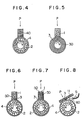
- the soft conductive film 4 for the collector ring 2 is formed in a manner as illustrated in Fig. 4 and the soft conductive film 3 for the collector shoe 1 is formed in a manner as illustrated in Fig. 5.
- a soft conductive rod 40 is pushed against the irregular or uneven surface of the conductive ceramics of collector ring 2 under the application of a pressure P. Under this condition, the collector ring 2 is rotated in a direction N in which the ring 2 is to be rotated in normal operation. Then, the soft conductive rod 40 is shaved off by the irregular surface of the conductive ceramics to produce chip powders which are adhered to the surface of the conductive ceramics of the collector ring 2. The adhered chip powders are gradually accumulated to form a glossy smoothed sliding surface with rotation of the collector ring 2.
- the conductive ceramics of the collector shoe 1 is pushed against a drum 30 of soft conductive material configurated as in the same shape as that of the collector ring 2 under the application of pressure P and the drum 30 is rotated in a direction N in which the ring 2, if used, will be driven in normal operation. Consequently, as in the case of the collector ring 2, the soft conductive drum 30 is shaved off by the irregular surface of the conductive ceramics of the collector shoe 1 to ultimately form a smoothed sliding surface of the collector shoe 1.
- a collector sliding surface is made smooth sufficiently'to ensure electrically stable operation.
- the rotation direction of the ring 2 or the drum 30 is the same as the direction in which the ring 2 is to be driven in normal operation, the contact voltage drop can be stabilized even in the initial phase of operation of an existing device mounted with the current collector.
- the current collector can provide stable performance from the beginning of operation when mounted to an existing electric machine, thereby preventing generation of spark.
- Fig. 6 shows the formation of the soft conductive film in another manner according to the invention, by which the soft conductive films 3 and 4 for the collector shoe 1 and the collector ring 2 can be formed simultaneously.
- soft conductive materials 50 are applied to forward and back sides of the collector shoe 1 of conductive ceramics in the direction N in forward rotation of the collector ring 2 which is also movable for rotation in the reverse direction N'.
- the soft conductive materials 50 are each arranged to have a lower end slightly projecting beyond the collector shoe 1 by mounting the soft conductive materials 50 movably relative to the collector shoe 1 and pushing each material against the collector ring 2 by a pressure independent of the pressure P applied to the collector shoe 1.
- the films 3 and 4 are both formed of the soft conductive materials 50 to provide the sliding surfaces of the collector shoe 1 and the collector ring 2.
- soft conductive materials 50 are applied to the collector shoe 1 at locations thereof different from those in Fig. 6. More particularly, longitudinal holes are formed in the collector shoe 1 and the soft conductive materials 50 are inserted in the holes. The soft conductive materials 50 are pushed against the collector ring 2 by a suitable pressure independent of the pressure applied to the collector shoe 1, so that the films 3 and 4 are formed in a similar manner to those of Fig. 6.
- a collector shoe 11 takes the form of an elongated plate, and soft conductive powders 60 are sprayed from a nozzle 5 into a space between the collector shoe 11 and collector ring 2 of conductive ceramics. Since the powders are sprayed towards the sliding contact portion between the collector shoe 11 and the collector ring 2 in the direction N in rotation of the collector ring 2 and the collector 11 is depressed against the ring 2 with a suitable pressure P, the soft conductive powders are generally oriented in a direction of rotation of the collector ring 2 so that the films 3 and 4 similar to those of the previous embodiments can be formed.
- the soft conductive material 50 or the nozzle 5 for spraying the soft conductive powders 60 is used for the formation of the sliding surface films of the collector shoe 1 or 11 and the collector ring 2.
- the soft conductive material or member may be arranged to an existing device to ensure that the device can be operated stably for a longterm operation.
- Fig. 9 shows an embodiment of such arrangement wherein a movable collecting member 12 equivalent to the collector ring 2 has a planar sliding surface which is movable in a direction N relative to the collector shoe 1.
- the soft conductive material 50 is arranged above the member 12 and ahead of the collector shoe 1 in the sliding direction N and is pushed against the movable collector member 12. In this manner, the soft conductive material 50 can be supplied constantly to the current collector and the collector can be operated stably for a long time.
- each of the paired collecting members of conductive ceramics is coated at its sliding surface with a film of soft conductive material which is softer than the conductive ceramics, thereby suppressing variations in the contact voltage drop across the sliding surfaces.
- the soft conductive material is softer than the conductive ceramics, the films of the soft conductive material are readily formed on the sliding surfaces of the two collecting members by making use of the rugged surface of the conductive ceramics of each member.
Landscapes
- Chemical & Material Sciences (AREA)
- Engineering & Computer Science (AREA)
- Ceramic Engineering (AREA)
- Motor Or Generator Current Collectors (AREA)
- Primary Cells (AREA)
Applications Claiming Priority (2)
| Application Number | Priority Date | Filing Date | Title |
|---|---|---|---|
| JP59123845A JPS614178A (ja) | 1984-06-18 | 1984-06-18 | 摺動集電装置 |
| JP123845/84 | 1984-06-18 |
Publications (3)
| Publication Number | Publication Date |
|---|---|
| EP0165515A2 EP0165515A2 (en) | 1985-12-27 |
| EP0165515A3 EP0165515A3 (en) | 1987-04-01 |
| EP0165515B1 true EP0165515B1 (en) | 1990-08-16 |
Family
ID=14870812
Family Applications (1)
| Application Number | Title | Priority Date | Filing Date |
|---|---|---|---|
| EP85106607A Expired EP0165515B1 (en) | 1984-06-18 | 1985-05-29 | Sliding current collector |
Country Status (4)
| Country | Link |
|---|---|
| US (1) | US4657818A (OSRAM) |
| EP (1) | EP0165515B1 (OSRAM) |
| JP (1) | JPS614178A (OSRAM) |
| DE (1) | DE3579197D1 (OSRAM) |
Families Citing this family (5)
| Publication number | Priority date | Publication date | Assignee | Title |
|---|---|---|---|---|
| EP0345199A3 (en) * | 1988-04-06 | 1990-05-09 | Nikolaos Tsagas | A device for indicating, on the vehicle's control panel inside the driver's cabinet during driving or stopping, the minimum and the maximum pneumatic pressure limits (lower and upper safety thresholds) in the inflated tyres of the vehicle. |
| JP3536484B2 (ja) * | 1995-11-17 | 2004-06-07 | 株式会社デンソー | 発電機 |
| DE102009029687A1 (de) * | 2009-09-23 | 2011-03-24 | Robert Bosch Gmbh | Kommutator zur Stromübertragung in einer elektrischen Maschine |
| DE102010041867A1 (de) * | 2010-10-01 | 2012-04-05 | Hoffmann & Co. Elektrokohle Ag | Stromübertragungsanordnung für elektromechanische Maschinen und Anlagen |
| CA3184623A1 (en) * | 2020-06-01 | 2021-12-09 | Cr Flight L.L.C. | Rotary electrical transformer with preferred lubricant |
Family Cites Families (9)
| Publication number | Priority date | Publication date | Assignee | Title |
|---|---|---|---|---|
| US1658677A (en) * | 1927-07-18 | 1928-02-07 | Gen Electric | Brush for dynamo-electric machines |
| US3042629A (en) * | 1960-07-11 | 1962-07-03 | Stackpole Carbon Co | Dynamoelectric brush |
| US3153163A (en) * | 1961-03-30 | 1964-10-13 | Gen Electric | Moving electric current collectors |
| DE2025216A1 (de) * | 1970-05-23 | 1971-12-02 | Carbone Ag | Bürste für Elektromotoren und Dynamos |
| US3714482A (en) * | 1971-10-27 | 1973-01-30 | Motorola Inc | Brush wear inhibitor for dynamoelectric machines |
| US4123122A (en) * | 1976-07-06 | 1978-10-31 | The Torrington Company | Bearing element |
| US4409295A (en) * | 1982-01-21 | 1983-10-11 | Olin Corporation | Electrical connector material |
| US4488771A (en) * | 1982-03-08 | 1984-12-18 | Allied Corporation | Fluorosilicone elastomers, method of making such elastomers and electrical connectors including the elastomers |
| JPS59232981A (ja) * | 1983-06-15 | 1984-12-27 | 株式会社日立製作所 | セラミツクスしゆう動材料 |
-
1984
- 1984-06-18 JP JP59123845A patent/JPS614178A/ja active Granted
-
1985
- 1985-05-29 DE DE8585106607T patent/DE3579197D1/de not_active Expired - Lifetime
- 1985-05-29 EP EP85106607A patent/EP0165515B1/en not_active Expired
- 1985-06-13 US US06/744,194 patent/US4657818A/en not_active Expired - Lifetime
Also Published As
| Publication number | Publication date |
|---|---|
| EP0165515A2 (en) | 1985-12-27 |
| JPH0247826B2 (OSRAM) | 1990-10-23 |
| US4657818A (en) | 1987-04-14 |
| JPS614178A (ja) | 1986-01-10 |
| DE3579197D1 (de) | 1990-09-20 |
| EP0165515A3 (en) | 1987-04-01 |
Similar Documents
| Publication | Publication Date | Title |
|---|---|---|
| CA1075295A (en) | Commutator rounding brush | |
| US6909219B2 (en) | Carbon brush for electric machine | |
| Ohmori et al. | Ultra-precision grinding of structural ceramics by electrolytic in-process dressing (ELID) grinding | |
| EP0165515B1 (en) | Sliding current collector | |
| US3382387A (en) | Electrical current collection and delivery method and apparatus | |
| US20120262025A1 (en) | Commutator for Power Transmission in an Electric Machine | |
| JPH05226047A (ja) | コンデンサ内蔵整流子及びその製造方法 | |
| US2780743A (en) | Electrical brush and dynamoelectric apparatus embodying the same | |
| KR20060065577A (ko) | 복합 전기 브러시 및 그 제조 방법 | |
| US2777081A (en) | Electrical brush and dynamoelectric apparatus embodying the same | |
| JPH0371582A (ja) | ブラシ | |
| US7094366B2 (en) | Resin-bonded graphite material, method for the production of a resin bonded graphite material and use thereof | |
| JP2000152567A (ja) | ブラシ | |
| JPH05182733A (ja) | 電気機械用カーボンブラシ | |
| Shobert | Sliding electrical contacts | |
| JPH09201016A (ja) | 回転電機用ブラシ保持装置 | |
| EP1201020B1 (en) | Motor assembly for power tools | |
| CN113206419A (zh) | 一种提高汇流环电刷磨弧效率装置及其应用方法 | |
| JP3549279B2 (ja) | 整流子電動機 | |
| Thompson et al. | The wear of graphite sliding on a steel surface and the influence of an electric current on the rate of wear | |
| CN2141941Y (zh) | 石墨-铜石墨复合材料电刷 | |
| JPH0458744A (ja) | 整流子モータのブラシ | |
| JPS59216445A (ja) | 回転電機の集電装置 | |
| JPH09149503A (ja) | 集電用すり部材 | |
| JP4361167B2 (ja) | 電気機械用カーボンブラシ |
Legal Events
| Date | Code | Title | Description |
|---|---|---|---|
| PUAI | Public reference made under article 153(3) epc to a published international application that has entered the european phase |
Free format text: ORIGINAL CODE: 0009012 |
|
| AK | Designated contracting states |
Designated state(s): DE GB |
|
| PUAL | Search report despatched |
Free format text: ORIGINAL CODE: 0009013 |
|
| AK | Designated contracting states |
Kind code of ref document: A3 Designated state(s): DE GB |
|
| 17P | Request for examination filed |
Effective date: 19870831 |
|
| 17Q | First examination report despatched |
Effective date: 19881108 |
|
| GRAA | (expected) grant |
Free format text: ORIGINAL CODE: 0009210 |
|
| AK | Designated contracting states |
Kind code of ref document: B1 Designated state(s): DE GB |
|
| REF | Corresponds to: |
Ref document number: 3579197 Country of ref document: DE Date of ref document: 19900920 |
|
| PLBE | No opposition filed within time limit |
Free format text: ORIGINAL CODE: 0009261 |
|
| STAA | Information on the status of an ep patent application or granted ep patent |
Free format text: STATUS: NO OPPOSITION FILED WITHIN TIME LIMIT |
|
| 26N | No opposition filed | ||
| PGFP | Annual fee paid to national office [announced via postgrant information from national office to epo] |
Ref country code: GB Payment date: 19930519 Year of fee payment: 9 |
|
| PG25 | Lapsed in a contracting state [announced via postgrant information from national office to epo] |
Ref country code: GB Effective date: 19940529 |
|
| PGFP | Annual fee paid to national office [announced via postgrant information from national office to epo] |
Ref country code: DE Payment date: 19940726 Year of fee payment: 10 |
|
| GBPC | Gb: european patent ceased through non-payment of renewal fee |
Effective date: 19940529 |
|
| PG25 | Lapsed in a contracting state [announced via postgrant information from national office to epo] |
Ref country code: DE Effective date: 19960201 |