EP0165407A2 - Drosselventil mit piezoelektrischem Betätigungsorgan - Google Patents
Drosselventil mit piezoelektrischem Betätigungsorgan Download PDFInfo
- Publication number
- EP0165407A2 EP0165407A2 EP85104882A EP85104882A EP0165407A2 EP 0165407 A2 EP0165407 A2 EP 0165407A2 EP 85104882 A EP85104882 A EP 85104882A EP 85104882 A EP85104882 A EP 85104882A EP 0165407 A2 EP0165407 A2 EP 0165407A2
- Authority
- EP
- European Patent Office
- Prior art keywords
- piezo
- valve
- electric
- control valve
- flow control
- Prior art date
- Legal status (The legal status is an assumption and is not a legal conclusion. Google has not performed a legal analysis and makes no representation as to the accuracy of the status listed.)
- Withdrawn
Links
- 239000012530 fluid Substances 0.000 claims abstract description 17
- 238000007639 printing Methods 0.000 claims description 12
- 239000000463 material Substances 0.000 claims description 8
- 239000002131 composite material Substances 0.000 claims description 4
- 241000510678 Falcaria vulgaris Species 0.000 claims description 3
- 239000002305 electric material Substances 0.000 claims description 2
- 238000004898 kneading Methods 0.000 claims 1
- 238000010298 pulverizing process Methods 0.000 claims 1
- 238000004080 punching Methods 0.000 claims 1
- 238000005245 sintering Methods 0.000 claims 1
- 238000010276 construction Methods 0.000 abstract description 5
- 238000013016 damping Methods 0.000 abstract description 3
- 230000008602 contraction Effects 0.000 description 7
- 230000000694 effects Effects 0.000 description 7
- 238000007641 inkjet printing Methods 0.000 description 5
- 239000000853 adhesive Substances 0.000 description 4
- 230000001070 adhesive effect Effects 0.000 description 4
- 230000003247 decreasing effect Effects 0.000 description 4
- 229910010293 ceramic material Inorganic materials 0.000 description 3
- 239000003595 mist Substances 0.000 description 3
- 239000013642 negative control Substances 0.000 description 3
- 239000004809 Teflon Substances 0.000 description 2
- 229920006362 Teflon® Polymers 0.000 description 2
- RTAQQCXQSZGOHL-UHFFFAOYSA-N Titanium Chemical compound [Ti] RTAQQCXQSZGOHL-UHFFFAOYSA-N 0.000 description 2
- 229910002113 barium titanate Inorganic materials 0.000 description 2
- JRPBQTZRNDNNOP-UHFFFAOYSA-N barium titanate Chemical compound [Ba+2].[Ba+2].[O-][Ti]([O-])([O-])[O-] JRPBQTZRNDNNOP-UHFFFAOYSA-N 0.000 description 2
- 238000006073 displacement reaction Methods 0.000 description 2
- 230000004048 modification Effects 0.000 description 2
- 238000012986 modification Methods 0.000 description 2
- 229920003002 synthetic resin Polymers 0.000 description 2
- 239000000057 synthetic resin Substances 0.000 description 2
- 229910052845 zircon Inorganic materials 0.000 description 2
- GFQYVLUOOAAOGM-UHFFFAOYSA-N zirconium(iv) silicate Chemical compound [Zr+4].[O-][Si]([O-])([O-])[O-] GFQYVLUOOAAOGM-UHFFFAOYSA-N 0.000 description 2
- 229910001252 Pd alloy Inorganic materials 0.000 description 1
- 230000005540 biological transmission Effects 0.000 description 1
- 239000013078 crystal Substances 0.000 description 1
- 230000005489 elastic deformation Effects 0.000 description 1
- 229920001971 elastomer Polymers 0.000 description 1
- 229910052751 metal Inorganic materials 0.000 description 1
- 239000002184 metal Substances 0.000 description 1
- SWELZOZIOHGSPA-UHFFFAOYSA-N palladium silver Chemical compound [Pd].[Ag] SWELZOZIOHGSPA-UHFFFAOYSA-N 0.000 description 1
- 230000010287 polarization Effects 0.000 description 1
- 229920001084 poly(chloroprene) Polymers 0.000 description 1
- 230000002787 reinforcement Effects 0.000 description 1
- 238000005070 sampling Methods 0.000 description 1
- 229920002379 silicone rubber Polymers 0.000 description 1
- 238000003466 welding Methods 0.000 description 1
- 238000004804 winding Methods 0.000 description 1
Images


Classifications
-
- F—MECHANICAL ENGINEERING; LIGHTING; HEATING; WEAPONS; BLASTING
- F16—ENGINEERING ELEMENTS AND UNITS; GENERAL MEASURES FOR PRODUCING AND MAINTAINING EFFECTIVE FUNCTIONING OF MACHINES OR INSTALLATIONS; THERMAL INSULATION IN GENERAL
- F16K—VALVES; TAPS; COCKS; ACTUATING-FLOATS; DEVICES FOR VENTING OR AERATING
- F16K31/00—Actuating devices; Operating means; Releasing devices
- F16K31/004—Actuating devices; Operating means; Releasing devices actuated by piezoelectric means
- F16K31/007—Piezo-electric stacks
-
- G—PHYSICS
- G05—CONTROLLING; REGULATING
- G05D—SYSTEMS FOR CONTROLLING OR REGULATING NON-ELECTRIC VARIABLES
- G05D7/00—Control of flow
- G05D7/06—Control of flow characterised by the use of electric means
- G05D7/0617—Control of flow characterised by the use of electric means specially adapted for fluid materials
- G05D7/0629—Control of flow characterised by the use of electric means specially adapted for fluid materials characterised by the type of regulator means
- G05D7/0635—Control of flow characterised by the use of electric means specially adapted for fluid materials characterised by the type of regulator means by action on throttling means
-
- H—ELECTRICITY
- H10—SEMICONDUCTOR DEVICES; ELECTRIC SOLID-STATE DEVICES NOT OTHERWISE PROVIDED FOR
- H10N—ELECTRIC SOLID-STATE DEVICES NOT OTHERWISE PROVIDED FOR
- H10N30/00—Piezoelectric or electrostrictive devices
- H10N30/20—Piezoelectric or electrostrictive devices with electrical input and mechanical output, e.g. functioning as actuators or vibrators
- H10N30/204—Piezoelectric or electrostrictive devices with electrical input and mechanical output, e.g. functioning as actuators or vibrators using bending displacement, e.g. unimorph, bimorph or multimorph cantilever or membrane benders
- H10N30/2041—Beam type
-
- H—ELECTRICITY
- H10—SEMICONDUCTOR DEVICES; ELECTRIC SOLID-STATE DEVICES NOT OTHERWISE PROVIDED FOR
- H10N—ELECTRIC SOLID-STATE DEVICES NOT OTHERWISE PROVIDED FOR
- H10N30/00—Piezoelectric or electrostrictive devices
- H10N30/50—Piezoelectric or electrostrictive devices having a stacked or multilayer structure
- H10N30/503—Piezoelectric or electrostrictive devices having a stacked or multilayer structure with non-rectangular cross-section orthogonal to the stacking direction, e.g. polygonal, circular
-
- H—ELECTRICITY
- H10—SEMICONDUCTOR DEVICES; ELECTRIC SOLID-STATE DEVICES NOT OTHERWISE PROVIDED FOR
- H10N—ELECTRIC SOLID-STATE DEVICES NOT OTHERWISE PROVIDED FOR
- H10N30/00—Piezoelectric or electrostrictive devices
- H10N30/80—Constructional details
- H10N30/87—Electrodes or interconnections, e.g. leads or terminals
- H10N30/871—Single-layered electrodes of multilayer piezoelectric or electrostrictive devices, e.g. internal electrodes
-
- H—ELECTRICITY
- H10—SEMICONDUCTOR DEVICES; ELECTRIC SOLID-STATE DEVICES NOT OTHERWISE PROVIDED FOR
- H10N—ELECTRIC SOLID-STATE DEVICES NOT OTHERWISE PROVIDED FOR
- H10N30/00—Piezoelectric or electrostrictive devices
- H10N30/80—Constructional details
- H10N30/88—Mounts; Supports; Enclosures; Casings
Definitions
- This invention relates to a flow control valve, and more particularly to a flow control valve simple in construction and reliable in operation and being able to control flow rate of a fluid such as air with high precision and at high speed.
- an ink sprayer of an ink jet type enlarging multicolor printing device concerned with the business of the applicant of this application disclosed, for example, Japanese Patent Application Publications Nos. 6,533/67 and 21,326/72.
- images of a literature and picture are optically and two-dimensionally scanned in a manner, for example, in the photo-picture transmission or the scanner for printing reproduction to obtain picture signals representing densities of the images.
- the picture signals are then converted into amounts of jetted ink from time to time to print the images on a recording medium such as a sheet of paper moving in synchronism with the scanning of the images of the literature.
- a flow control valve 1 (simply referred to hereinafter as "control valve") for air flow comprises a valve body 3 suspended at a center of a leaf spring 2 in the form of a disc.
- the valve body 3 is driven in its axial direction by a mutual action of a moving coil 4 integrally arranged on the leaf spring 2 and supplied with electric current correspondingly to the picture signals and an annular magnetic field formed between first and second magnetic poles 5 and 6, so that compressed air introduced from a compressed air source (not shown) through an air supply pipe 7 into a valve chamber 8 is supplied into an ink jet nozzle 12 through an air feeding pipe 11 and an annular clearance between a tip end of the valve body 3 and a valve seat 9, which is variable in response to magnitudes of the picture signals.
- a moving coil 4 integrally arranged on the leaf spring 2 and supplied with electric current correspondingly to the picture signals and an annular magnetic field formed between first and second magnetic poles 5 and 6, so that compressed air introduced from a compressed air source (not shown) through an air supply pipe 7 into a valve chamber 8 is supplied into an ink jet nozzle 12 through an air feeding pipe 11 and an annular clearance between a tip end of the valve body 3 and a valve seat 9, which is variable in response to magnitudes
- the ink jet nozzle 12 includes a cylindrical air nozzle 13 and an ink nozzle 14 coaxially arranged in the air nozzle 13 to mix the air in the air nozzle 13 with the ink sucked in the ink nozzle 14 with the aid of the Bernoulli's theorem to form ink mist.
- the control valve 1 shown in Fig. 1 comprises a permanent magnet 15 for producing the magnetic field and a needle valve 16 for adjusting the amount of the ink.
- Such a control valve 1 above constructed has been actually used and has fulfilled its aimed function for many years.
- a spring constant of the leaf spring 2 cannot be large and hence a characteristic frequency of a vibration system having an inertia mass consisting of the valve body 3, moving coil 4, bobbin 17 for the coil and the like cannot be large; so that a response frequency of the control valve is at the most hundreds Hz.
- the moving coil 4 is made as a multiplex winding coil to increase its driving force, the responsibility is not improved due to an increase in inertia.
- valve body 3 when the valve body 3 is moved in its axial direction from one position to the other, it would do so-called overshooting unless its movement is effectively damped. Namely, due to the inertia of the vibration system, the valve body 3 will overshoot to cause excessive opening or closing of the control valve. Furthermore, such an overshooting causes the valve body 3 to vibrate in a complicated manner in conjunction with returning function of the leaf spring 2 and rebounding of the valve body 3 due to collision against the valve seat 9.
- the damping of the vibration system is effected by making small the output impedance of an amplifier for supplying current to the moving coil, or by electromagnetic braking with the aid of electromotive force caused in the moving coil 4 by the overshooting, or by electrical braking means which is not explained because it is not essential for the invention.
- the overshoot cannot be completely eliminated, so that excessive air flow and ambiguous closing of the valve due to overshooting resulting in variation or unevenness in density of images and lower sharpness.
- a flow control valve comprises a valve chamber having an inlet pipe and an outlet pipe for a fluid to be controlled, a valve seat provided in said valve chamber on a side of the outlet pipe, a valve body provided in said valve chamber and having one end in opposition to said valve seat, and driving means including a piezo-electric unit deformable in response to voltage applied to the unit so as to drive said valve body toward and away from the valve seat to close and open an opening of said valve seat.
- the piezo-electric unit comprises a plurality of piezo-electric elements and a plurality of thin electrode plates, these elements and plates being alternately laminated to form a unitary bar-like body, and lead wires connecting every other said electrode plates in parallel for applying simultaneously to all said piezo-electric elements bias voltage for determining a zero point of fluid flow and control voltage in a direction opposite to that of said bias voltage.
- the number of said piezo-electric elements is m times as many as 2 n- 1 where m is a positive integral number, one or more, and n is a positive integral number, two or more and equal to the number of bits of binary coded control signals, and said piezo-electric elements are divided into groups whose number is equal to the number of said bits, the number of the piezo-electric elements in one said group being m x 2 1 1 where i is an order of the groups, and said lead wires being connected to said element such that the voltage is applicable in parallel to the piezo-electric elements in each said group independently from the other groups in a manner that when all the bits are "0", a zero point of the fluid flow is set and when the bit is "I", the piezo-electric elements in the group corresponding to the bit is driven in a direction opposite to that when the bias voltage is applied.
- the piezo-electric unit comprises a bimorph type piezo-electric element which is bent when voltage is applied thereto, pivotal means for supporting ends of the piezo-electric element to permit the ends to tilt and a joining unit for connecting said valve body to said piezo-electric element.
- the pivotal means comprises guide blocks fitted on ends of said element and having ridges, a U-shaped holder made of a long leaf spring having a pair of perpendicularly bent ends, and receiving blocks formed with V-shaped grooves and fixed to said bent ends of said U-shaped holder so as to receiving said ridges of the guide blocks in the V-shaped grooves in the receiving blocks, thereby permitting the ends of the element to tilt.
- a flow control valve according to the invention comprises a valve casing 18 in the form of a metal cylinder having at one end (on a right end in Fig. 2) a front cap 19 and at the other end a rear cap 21 hermetically threadedly engaged thereon, respectively, to form a valve chamber 8 therein.
- an air supply pipe 7 as an inlet pipe for a controlled fluid (compressed air in this embodiment) and an air feed pipe 11 as an outlet pipe.
- the air feed pipe 11 passes through the front cap 19 and is coaxially and hermetically threadedly engaged therewith and formed with an annular valve seat 9 at an inner end facing to an inside of the valve chamber 8.
- a valve body 3 having a conical end is arranged in the proximity of the valve seat 9 with a tip end of the valve body 3 in opposition to an opening of the valve seat 9.
- the valve body 3 is supported at its center by a leaf spring 2 and its bottom portion integrally and tightly jointed to a driving unit 22.
- the leaf spring 2 is for example, a circular elastic plate covering an opening of the valve casing and is circumferentially or radially formed with at least one slit (not shown) to enable the compressed air flowed through the air supply pipe 7 into the valve chamber 8 to flow into the air feed pipe 11. Moreover, the leaf spring 2 is provided to facilitate the alignment of the valve body 3 with the valve seat 9 and can be dispensed because it is not essential for the invention.
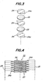
- the driving unit 22 comprises a plurality of piezo-electric elements 23 in the form of circular discs and a plurality of thin electrode plates 24 similar in shape to the elements 23 alternately laminated and integrally jointed by means of a conductive adhesive to form a bar-like body.
- a conductive adhesive to form a bar-like body.
- to one end (right end viewed in Fig. 2) of the driving unit 22 is attached the valve body 3 for example by an adhesive.
- the other end of the driving unit 22 is coaxially attached to an inner surface of the rear cap 21 forming an inner wall of the valve chamber 8.
- a material of the piezo-electric elements 23 is preferably a sintered ceramic material having the piezo-electric effect, for example, PZT (zircon titanate) and barium titanate used as ultrasonic wave oscillator elements.
- Each the electrode plate 24 is provided at its outer periphery with a connection piece 24a.
- the electrode plates 24 are arranged between the piezo-electric elements 23 so as to arrange the connection pieces 24a alternately extending in opposite directions as shown in Fig. 4.
- the connection pieces 24a are arranged in two rows along generation lines of the driving unit 22 and in symmetry with its axis and electrically connected to a pair of common lead wires 25 as shown in Fig. 4.
- These lead wires 25 are introduced through a connector 26 arranged on the valve casing 18 (Fig. 2) out of the valve chamber 8 and connected through an amplifier (not shown) to, for example, a control signal source (not shown) for a printing device.
- the driving unit 22 may be coated with a soft synthetic resin for the purpose of reinforcement of it, because the resistance of the synthetic resin is slight in comparison with the force caused when the voltage is applied to the piezo-electric elements as explained hereinafter.
- the control valve constructed as above described according to the invention is used in a manner that a constant positive bias voltage V b plus a negative control voltage V c variable with time, that is, V b -V c is applied to the groups of piezo-electric elements 23 of the driving unit as shown in Fig. 5.
- V is in proportion to the picture signals obtained in scanning the images of the literature and picture in the enlarging multicolor printing device initially mentioned.
- the positive voltage means the voltage having a direction for extending the driving unit
- the negative voltage means the voltage having the direction opposite to that of the positive voltage.
- a large voltage is previously applied to the piezo-electric elements 23 of the driving unit to align directions of polarization of their crystal grains with directions of their thickness.
- valve body 3 (Fig. 2) closes the opening of the valve seat 9 that is, the flow rate of the compressed air being zero according to the material and thickness and the number of the piezo-electric elements in the driving unit.
- the expression that the valve body 3 closes the opening of the valve seat 9 used herein means the condition that the ink is not jetted from the ink nozzle 12 (Fig. 1) including the condition of the tip end of the valve body 3 abutting against the valve seat 9, even if a small amount of compressed air is leaking at the opening of the valve seat 9.
- the extending distance d of the driving unit 22 increases along a curve a to the maximum set extending distance dm at the bias voltage V b , if the charged amount of the dielectric piezo-electric elements 23 is zero as shown in Fig. 6. Thereafter, when the voltage V is decreased, the extending distance d is progressively decreased along a curve ⁇ which is substantially straight to a strain where the voltage is zero.
- the extending distance d of the driving unit increases along a curve y starting from the strain s which is also substantially straight and close to the curve p to the maximum set extending distance dm at the applied bias voltage V b .
- the voltage applied to the elements 23 does not exceed the bias voltage V b , so that the extending distance d varies linarly from the maximum distance dm to smaller values.
- the clearance between the valve body 3 (Fig. 2) and the valve seat 9 varies in porportion to the control voltage V , while the amount of the compressed air jetted from the air feed pipe 11 (Fig. 1) is in proportion to the clearance. Therefore, the amount of the ink jetted from the ink nozzle 12 is in proportion to the picture signals.
- the piezo-electric elements have characteristics capable of precisely controlling their extension and contraction so as to enable the extension and contraction of the driving unit 22 to be controlled with a high accuracy in the order of 0.01 p. Furthermore, the frequency responsibility of the piezo-electric elements is very high such as 50 to several hundreds kHz which can be understood from the fact that they are used as ultrasonic wave oscillator elements.
- the driving force of the driving unit 22 is very large such as several tens to several hundreds Kg so as to drive the valve body 3 easily.
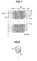
- Fig. 7 illustrates a driving unit 22 of a control valve of another embodiment of the invention, which drives a valve body with the aid of binary-coded control signals.
- picture signals as analog signals outputted from the image scanning system from time to time are sampled with constant short periods of intervals to obtain sampled signals which are converted into, for example, binary-coded control signals C o , C 1 , C 2 , ⁇ , C 7 consisting of 8 bits by the use of an analog to digital converter (not shown).
- These digital control signals of 8 bits are discontinuous signals of 256 kinds from 0 to 255.
- the density of images can be divided into 256 grades, the density can be sufficiently deemed as continuous.
- the number of the bits of the above digital control signals can be increased or decreased if required.
- the piezo-electric elements in the driving unit 22 are 255 because m is 1 (one) for the sake of clarity of the drawing.
- the uppermost piezo-electric element 23-1 is in 1st group
- two next piezo-electric elements 23-2 and 23-3 are in 2nd group
- four next piezo-electric elements 23-4 to 23-7 are 3rd group
- ⁇ elements 23-128 to 23-255 are 8th group.
- Lead wires 25 are connected to the elements such that the voltage is applied in parallel to the piezo-electric elements in one group independently from the other groups.
- the 1st to 8th groups of the elements are made corresponding to digital control signals C O -C 7 , respectively.
- a constant negative voltage V whose absolute value is less than V b is applied in parallel to the piezo-electric elements, when the bit is "1" according to whether it is "0" or "1" (Fig. 6).
- the groups are so set that the driving unit extends the maximum distance to the zero flow rate position to close the opening of the valve seat, when the above bias voltage V b is permanently applied in parallel to all the piezo-electric elements of the driving unit 22 and the respective bits of the digital control signals C are "0".
- the values of the constant negative control voltage V a is so set that the driving unit 22 contracts to the minimum length to open the annular clearance between the valve body 3 (Fig. 2) and the valve seat 9 when the negative voltage V a is applied to all the piezo-electric elements of the driving unit 22 or all the bits of the digital control signals C are "1".
- control valve equipped with the driving unit shown in Fig. 7 according to the invention is substantially the same as that shown in Fig. 2 with the exception that lead wires 25 are somewhat modified. Therefore, the control valve will not be explained and illustrated in more detail.
- the control valve of this embodiment samples picture signals several thousands per one second to convert the sampled signals into digital control signals C O -C 7 of 8 bits by an analog to digital converter.
- the digital signals are then supplied to the corresponding groups of the piezo-electric elements through amplifiers, thereby applying the negative voltage V whose absolute value is less than that of the positive bias voltage V b as shown in Fig. 7.
- the time for applying the voltage V is usually determined so as to be substantially the same time intervals for the sampling.
- the negative voltage V a is applied to the piezo-electric elements 23 of binary-coded numbers represented by the control signals C, with the result that the clearance between the valve seat and the valve body and the amount of the compressed air leaked from the valve chamber 8 increase or decrease in proportion to the control signals, so that the amount of the ink jetted from the ink nozzle 12 (Fig. 1) varies linearly with the control signals C which is proportional to picture signals.
- a plurality of thin piezo-electric units 27 constructed as mentioned later are laminated so as to angularly shift electrode plates about their axes little by little to from a driving unit 22.
- distances between the piezo-electric units 27 are exaggeratedly shown for the sake of clarity.
- a crystalline piezo-electric material is pulverized and kneaded with, for example, an organic paste, and the material with the paste is extended in a thickness, for example, several tens to several hundreds p to form a piezo-electric sheet 27b as shown in Fig. 9.
- Electrode films of, for example-, silver-palladium alloy are printed on both surfaces of the piezo-electric sheet 27b to form a composite unit which is punched to obtain discs having connection pieces 27a extending therefrom.
- piezo-electric units 27 are laminated into a cylindrical shape having connection pieces 27a spirally extending as shown in Fig. 8 and the laminated units are sintered to form the driving unit 22.
- connection pieces 27a are spirally arranged to facilitate the connection of the lead wires 25 to the connection pieces 27a.
- a valve body 3 is elongated and a valve closing and opening portion consisting of a valve seat 9 and a valve body 3 is arranged in the proximity of an ink jetting opening of an ink nozzle 12 (Fig. 1).
- a center portion of the valve body 3 is supported by a sleeve 28 made of for example slippery Teflon in order to prevent the valve body 3 from swinging.
- a volume of an air flow passage from the valve closing and opening portion to the ink jetting opening becomes small, whereby the amount of the jetted ink precisely follows the control signals to make sharp the obtained images.
- the volume of the air flow passage from the valve closing and opening portion to the ink jetting opening is large as shown in Fig. 1, the pressure of the compressed air delivered from the valve closing and opening portion into the passage progressively increases to the maximum pressure when for example the valve is opened from a completely closed condition, so that the air flow at the ink jetting opening progressively increases without rapidly increasing.
- edges of the images obtained from original images having sharp edges are blurred to lower the sharpness of the images.
- the control valve shown in Fig. 10 eliminate such a disadvantage to make sharp images.
- the elongated valve body 3 as shown in Fig. 10 increases an inertia resistance and a frictional resistance is caused due to the sleeve 28, these resistances are negligible small for the driving unit 22 having the strong driving force owing to the piezo-electric effect according to the invention.
- the arrangement shown in Fig. 10 can be realized only by the control valve utilizing the piezo-electric effect according to the invention.
- a valve casing 48 consists of two different volume portions and is closed at its ends to form an air-tight valve chamber 38 therein.
- an air supply pipe 37 as an inlet pipe for a controlled fluid (compressed air in this embodiment) and an air feed pipe 41 as an outlet pipe.
- the air supply pipe 37 is connected to the valve casing through a fitting 49 passing through one end plate of the valve casing 48 (on the right side of Fig. 11).
- the air feed pipe 41 passes through the other end plate of the valve casing 48 and is threadedly engaged therein coaxially to a center axis of the valve casing in an air-tight manner.
- the air feed pipe 41 is formed with an annular valve seat 39 at its inner end facing to the valve chamber 38.
- a valve body 33 having a conical end is arranged in the proximity of the valve seat 39 with the conical end in opposition to an opening of the valve seat 39.
- the valve body 33 is slidably supported at its center portion in a sleeve 21 fitted in the valve casing and is integrally jointed at its inner end through a joining-unit 52 with a driving plate 53 which is a so-called bimorph type piezo-electric element (Fig. 12).
- the sleeve 51 is a thick disc made of a material having a small coefficient of friction, such as Teflon and is formed in its axis with a bore (no reference number) for fitting the valve body 3 therein and in the proximity of the bore with at least one vent hole 54 in parallel with the bore and passing through the sleeve 51 for permitting the air flowed through the air supply pipe 37 into the valve chamber 38 to flow into the air feed pipe 41.
- a U-shaped holder 55 made of a long leaf spring having a pair of perpendicularly bent ends is fixed to an inside of the end plate of the valve casing 48.
- the driving plate 53 is elastically held between the pair of bent ends of the U-shaped holder 55.
- the driving plate 53 is bent or curved when voltage is applied thereto in its thickness direction because it is the bimorph type piezo-electric element as above mentioned.
- a material of the piezo-electric element is preferably a ceramic material, for example, PZT (zircon titanate) and barium titanate used as ultrasonic wave oscillator elements.
- a ceramic material having the piezo-electric effect is sintered to form long plates which are then attached to each other, for example, by a conductive adhesive to obtain the driving plate 53.
- the driving plate 63 is provided at its ends with guide blocks 57 integrally therewith as shown in Figs. 11 and 12.
- Each the guide block 57 is a V-shaped rod formed with a groove for tightly fitting therein the end of the driving plate 53 (Fig. 11).
- each the bent end of the U-shaped holder 55 is fixed a receiving block 58 in the form of a rod formed with a V-shaped groove for engaging and receiving a ridge of the guide block 57.
- the driving plate 53 is supported so as to permit its ends to be tilted in a plane of Fig. 11.
- a distance between the bent ends of the U-shaped holder 55 under a free condition is set a somewhat smaller than that when the driving plate is supported therein as shown in Figs. 11 and 12, so that the guide blocks 57 and the receiving blocks 58 are resiliently engaged with each other without any play therebetween.
- the joining unit 52 for connecting the valve body 33 to the driving plate 53 is constructed as follows.
- the joining unit 52 comprises a first support 59 and a second support 60.
- Each the support 59 or 60 is a rod extending in a width direction of the driving plate 53 and formed with a ridge having an isosceles triangular cross-section in opposition to the driving plate 53.
- the first and second supports are kept in parallel with each other and embrace a center of the driving plate 53.
- the second support 60 is provided at its ends with guide rods 61 on a surface of the support 60 facing to the other support 59.
- Each the guide rod 61 is perpendicularly planted in the surface of the support 60 and is formed at its end with male screw-threads (not shown).
- the first support 59 is formed with guide apertures (no reference numerals) passing therethrough for sidably fitted therein the guide rods 61 such that their threaded ends extend beyond the first support 59.
- valve body 33 is located at the center of an upper surface of the first support 59 as viewed in Fig. 12.
- a V-shaped leaf spring 62 is provided on the first support 59 and is formed at its center with an opening adapted to loosely fitted with a stem of the valve body 33 and at both the ends with notches adapted to engage the ends of the guide rods 61 as shown in Fig. 12.
- both the ends of the leaf spring 62 are adapted to engage nuts threadedly engaged with the ends of the guide rods 61.
- the first and second supports 59 and 60 are urged toward each other by the resilience of the leaf spring 62, so that the valve body 33 is attached to the center of the driving plate 53 through the first and second supports which are in line contact with the driving plate.
- a damper 63 made of, for example, silicon rubber or neoprene is provided to connect between the second support 60 and the U-shaped holder 55, although the damper 63 is not essential for the invention.
- This damper 63 serves to rapidly damp the resonance determined by inertia masses of the valve body 33, the joining unit 52 and the like and the material, dimension and the like of the driving plate 53. If the resonance frequency is higher than the maximum frequency of images required for the control valve, such a damper 63 is not needed.
- a reference numeral 64 in Fig. 11 denotes a terminal for a lead line for applying voltage to the driving plate 54.
- control valve constructed as above described according to the invention is used in a manner that a constant positive bias voltage V b plus negative control voltage V variable with time, that is, V b -V c is applied to the driving plate 53 as shown in Fig. 14. It is understood that for example the control voltage V is in proportion to the picture signals obtained in scanning the images of the literature and picture in the enlarging multicolor printing device.
- the above positive voltage is difined in the following manner.
- the driving plate 53 as a bimorph type piezo-electric element are tiltably supported by the support means in the form of knife edges in the control valve of the embodiment shown in Figs. 11 and 12, the driving plate 53 easily deforms without any obstruction as shown in Fig. 15 so as to move the valve body 33 secured to the center of the driving plate 53 with the jointing unit 52 in the axial direction of the valve body to control the annular clearance or the opening of the control valve between the valve seat 9 (Fig. 11) and the valve body 33.
- the positive voltage means that for moving the valve body 33 toward the valve seat 39
- the negative voltage means that having the direction opposite to that of the positive voltage.
- the setting of the absolute valve of the bias voltage V b is effected in the same manner as in the embodiment shown in Fig. 2.
- the closing of the opening of the valve seat is defined in the same manner as in Fig. 2.
- respective parameters are so set that the valve body 33 abuts against the valve seat 39 to completely close the opening of the valve seat 39 when the deformation of the driving plate 53 becomes the maximum set value dm.
- the bias voltage V b is set at a value somewhat lower than the voltage V b ' corresponding to the maximum set value dm as shown in Fig. 14, so that even if the control voltage is zero, the clearance between the valve body and the valve seat is kept opened slightly as shown 6 in Fig. 14 so as to leak a small amount of compressed air. This improves the responsibility of the control valve to the variation in control signal.
- the amount of the air leaked from the valve should be set so as not to jet the ink out of the ink nozzle 12 (Fig. 1).
- the hysteresis curve a of initial voltage application is neglected and the remaining strain ⁇ is set at an origin 0 of the coordinates.
- the bimorph type piezo-electric elements exhibit comparatively large deformations in comparison with so-called laminated type piezo-electric elements consisting of a number of laminated piezo-electric elements variable in thickness when applying voltage thereto, so that the stroke of the order of 100 p of the valve body for the control valve can be easily obtained by the bimorph type elements.
- the driving force of the bimorph element is very large such as several Kg in comparison with that of the hitherto used moving coil so as to easily drive the valve body 33 and the joining unit integral therewith.
- the driving plate 23 as a piezo-electric element has characteristics capable of precisely controlling their deformations so as to control the valve body 33 integrally jointed to the driving plate 53 with a high accuracy of the order of 0.1 p.
- the frequency responsibility of the bimorph elements is very high such as 20 to several hundreds kHz which can be understood from the fact that they are used as ultrasonic wave oscillator elements.
- the variation in dimension of the driving plate in its length direction is the most several p when deformations of the driving plate to be converted to the movement of the valve body 33 is 100 p.
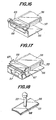
- a reference numeral 65 denotes a support having a U-shaped cross-section in which each end of the driving plate is fitted.
- the supports 65 are integrally jointed to the driving plate 53 at its ends.
- a support shaft 66 is integrally jointed to a surface of the support 65 opposite to the driving plate 53 for example by welding.
- a U-shaped holder 55 has bent ends which rotatably support the support shafts 66, respectively.
- Fig. 17 illustrates a further modification of the embodiment according to the invention.
- guide blocks 57 are provided on bent ends of a holder 55, and receiving blocks 58 are provided on both ends of a driving plate 53.
- the holder 55 is formed at its each end with a pair of support pieces 67 integral therewith to embrace the receiving blocks 58.
- the pairs of support pieces 67 effectively prevent the driving plates 53 from being shifted relative to the holder 55.
- a valve body 33 and a driving plate 53 are connected by a connecting plate 68 which is a thin rubber plate having a comparatively high hardness with the aid of an adhesive between the valve body 33 and the driving plate 53 respectively and the connecting plate 68.
- the deformation of the driving plate when curved is somewhat absorbed by an elastic deformation of the connecting plate 68 to keep stably the connection between the valve body 33 and the driving plate 53.
- this embodiment is simple in construction without a joining unit 52 and achieves decrease in inertia resistance.
- the valve body is driven by the driving unit made of laminated piezo-electric elements or bimorph type piezo-electric elements having high frequency responsibility so as to control the fluid flow in short interval of time. Therefore, the control valve according to the invention is applicable to the above mentioned enlarging multicolor printing device to greatly improve resolution and sharpness of obtained images.
- the opening of the valve or the fluid flow to be controlled can be precisely controlled because of high responsibility between the control voltage to be applied and extension and contraction of the driving unit or between the control voltage and the deformation of the driving plate. Therefore, the density and gradation of original images can be reproduced in high fidelity with the above enlarging multicolor printing device.
- the driving force of the driving unit is very strong of the order of several Kg to ensure the positive operation of the control valve so as to increase its reliability. Furthermore, such a strong driving force need not provide damping means for the vibration system of the valve and therefore makes simple in construction the control valve itself, control circuit and power source therefor and the like.
- the constant bias voltage is applied to all the piezo-electric elements or the driving plate to close the control valve completely and the control voltage is applied in the direction decreasing the bias voltage, so that the hysteresis characteristics (Fig. 6) of the extension and contraction of the piezo-electric elements or the deformation of the driving plate relative to the applied voltages can be rationaly utilized.
- the fluid to be controlled is the air in the embodiments, it is of course possible to use any other fluids other than the air.
- control signal voltage and the bias voltage for positioning the zero flow point are applied in parallel to the piezo-electric elements.
- voltage multiplied by the number of the laminated piezo-electric elements may be applied in series to ends of the elements or to respective groups of the elements corresponding to bits of binary coded control signals. With this arrangement, terminals of the driving unit can be easily constructed although a high voltage bias power source and control signal output amplifiers are needed.
Applications Claiming Priority (4)
| Application Number | Priority Date | Filing Date | Title |
|---|---|---|---|
| JP8467584A JPS60227078A (ja) | 1984-04-26 | 1984-04-26 | 流量制御弁 |
| JP84675/84 | 1984-04-26 | ||
| JP19210684U JPH025163Y2 (de) | 1984-12-18 | 1984-12-18 | |
| JP192106/84U | 1984-12-18 |
Publications (2)
| Publication Number | Publication Date |
|---|---|
| EP0165407A2 true EP0165407A2 (de) | 1985-12-27 |
| EP0165407A3 EP0165407A3 (de) | 1986-06-18 |
Family
ID=26425670
Family Applications (1)
| Application Number | Title | Priority Date | Filing Date |
|---|---|---|---|
| EP85104882A Withdrawn EP0165407A3 (de) | 1984-04-26 | 1985-04-22 | Drosselventil mit piezoelektrischem Betätigungsorgan |
Country Status (2)
| Country | Link |
|---|---|
| EP (1) | EP0165407A3 (de) |
| AU (1) | AU4162285A (de) |
Cited By (19)
| Publication number | Priority date | Publication date | Assignee | Title |
|---|---|---|---|---|
| EP0331461A1 (de) * | 1988-03-02 | 1989-09-06 | Toto Ltd. | Spülvorrichtung für WC-Becken |
| DE3925686A1 (de) * | 1988-08-25 | 1990-03-08 | Hydraulik Ring Gmbh | Einrichtung zur stetigen beeinflussung eines fluidstromes, insbesondere in einem ventil |
| FR2639086A1 (fr) * | 1988-11-17 | 1990-05-18 | Smc Corp | Dispositif de clapet a lamelles pour buse ou orifice |
| EP0574945A1 (de) * | 1992-06-19 | 1993-12-22 | MARCO SYSTEMANALYSE UND ENTWICKLUNG GmbH | Vorrichtung zur Betätigung eines Ventilelementes |
| US5356034A (en) * | 1992-01-30 | 1994-10-18 | Boehringer Mannheim Gmbh | Apparatus for the proportioned feeding of an analysis fluid |
| US5469586A (en) * | 1988-03-02 | 1995-11-28 | Toto Ltd. | Toilet bowl flushing device |
| WO1997023815A1 (en) * | 1995-12-21 | 1997-07-03 | Kimberly-Clark Worldwide, Inc. | Ultrasonic liquid flow control apparatus and method |
| EP0810398A2 (de) * | 1996-05-30 | 1997-12-03 | Nass Magnet GmbH | Elektrisch ansteuerbares Schieberventil |
| WO1997049500A1 (en) * | 1996-06-26 | 1997-12-31 | Kimberly-Clark Worldwide, Inc. | An apparatus and method for controlling an ultrasonic transducer |
| US5803106A (en) * | 1995-12-21 | 1998-09-08 | Kimberly-Clark Worldwide, Inc. | Ultrasonic apparatus and method for increasing the flow rate of a liquid through an orifice |
| US6053424A (en) * | 1995-12-21 | 2000-04-25 | Kimberly-Clark Worldwide, Inc. | Apparatus and method for ultrasonically producing a spray of liquid |
| WO2000038252A1 (fr) | 1998-12-18 | 2000-06-29 | Denso Corporation | Corps multicouche piezoelectrique |
| WO2000079162A1 (de) * | 1999-06-19 | 2000-12-28 | Robert Bosch Gmbh | Piezoaktor |
| CN1081770C (zh) * | 1998-04-28 | 2002-03-27 | 东芝株式会社 | 电磁阀 |
| US6380264B1 (en) | 1994-06-23 | 2002-04-30 | Kimberly-Clark Corporation | Apparatus and method for emulsifying a pressurized multi-component liquid |
| US6395216B1 (en) | 1994-06-23 | 2002-05-28 | Kimberly-Clark Worldwide, Inc. | Method and apparatus for ultrasonically assisted melt extrusion of fibers |
| US7028347B2 (en) | 2004-09-01 | 2006-04-18 | Sanderson Dilworth D | Digital electronic volume/flow control sensor toilet |
| GB2498398A (en) * | 2012-01-16 | 2013-07-17 | Spirax Sarco Ltd | Linear Piezo-electric actuator for a valve |
| CN112807944A (zh) * | 2021-02-02 | 2021-05-18 | 浙江物产环能浦江热电有限公司 | 一种用于尾气脱硝的氨水流量调节系统及调节方法 |
Families Citing this family (3)
| Publication number | Priority date | Publication date | Assignee | Title |
|---|---|---|---|---|
| ZA969680B (en) | 1995-12-21 | 1997-06-12 | Kimberly Clark Co | Ultrasonic liquid fuel injection on apparatus and method |
| US6663027B2 (en) | 2000-12-11 | 2003-12-16 | Kimberly-Clark Worldwide, Inc. | Unitized injector modified for ultrasonically stimulated operation |
| US6543700B2 (en) | 2000-12-11 | 2003-04-08 | Kimberly-Clark Worldwide, Inc. | Ultrasonic unitized fuel injector with ceramic valve body |
Citations (6)
| Publication number | Priority date | Publication date | Assignee | Title |
|---|---|---|---|---|
| US3553371A (en) * | 1967-02-28 | 1971-01-05 | Nippon Enlarging | Method for enlarged muticolor printing and a device therefor |
| US4018241A (en) * | 1974-09-23 | 1977-04-19 | The Regents Of The University Of Colorado | Method and inlet control system for controlling a gas flow sample to an evacuated chamber |
| FR2425599A1 (fr) * | 1978-05-10 | 1979-12-07 | Commissariat Energie Atomique | Vanne de reglage du debit d'un fluide |
| GB2094940A (en) * | 1981-02-18 | 1982-09-22 | Nissan Motor | Piezo-electric valve |
| US4384230A (en) * | 1980-11-06 | 1983-05-17 | United Technologies Corporation | Digital piezoelectric actuator |
| EP0148630A2 (de) * | 1983-12-22 | 1985-07-17 | Paradygm Science And Technologies, Inc. | Bedienungsvorrichtung für ein Regelventil oder ein ähnliches System |
-
1985
- 1985-04-22 EP EP85104882A patent/EP0165407A3/de not_active Withdrawn
- 1985-04-23 AU AU41622/85A patent/AU4162285A/en not_active Abandoned
Patent Citations (6)
| Publication number | Priority date | Publication date | Assignee | Title |
|---|---|---|---|---|
| US3553371A (en) * | 1967-02-28 | 1971-01-05 | Nippon Enlarging | Method for enlarged muticolor printing and a device therefor |
| US4018241A (en) * | 1974-09-23 | 1977-04-19 | The Regents Of The University Of Colorado | Method and inlet control system for controlling a gas flow sample to an evacuated chamber |
| FR2425599A1 (fr) * | 1978-05-10 | 1979-12-07 | Commissariat Energie Atomique | Vanne de reglage du debit d'un fluide |
| US4384230A (en) * | 1980-11-06 | 1983-05-17 | United Technologies Corporation | Digital piezoelectric actuator |
| GB2094940A (en) * | 1981-02-18 | 1982-09-22 | Nissan Motor | Piezo-electric valve |
| EP0148630A2 (de) * | 1983-12-22 | 1985-07-17 | Paradygm Science And Technologies, Inc. | Bedienungsvorrichtung für ein Regelventil oder ein ähnliches System |
Cited By (27)
| Publication number | Priority date | Publication date | Assignee | Title |
|---|---|---|---|---|
| EP0331461A1 (de) * | 1988-03-02 | 1989-09-06 | Toto Ltd. | Spülvorrichtung für WC-Becken |
| US4989277A (en) * | 1988-03-02 | 1991-02-05 | Toto Ltd. | Toilet bowl flushing device |
| US5469586A (en) * | 1988-03-02 | 1995-11-28 | Toto Ltd. | Toilet bowl flushing device |
| DE3925686A1 (de) * | 1988-08-25 | 1990-03-08 | Hydraulik Ring Gmbh | Einrichtung zur stetigen beeinflussung eines fluidstromes, insbesondere in einem ventil |
| FR2639086A1 (fr) * | 1988-11-17 | 1990-05-18 | Smc Corp | Dispositif de clapet a lamelles pour buse ou orifice |
| US5356034A (en) * | 1992-01-30 | 1994-10-18 | Boehringer Mannheim Gmbh | Apparatus for the proportioned feeding of an analysis fluid |
| EP0574945A1 (de) * | 1992-06-19 | 1993-12-22 | MARCO SYSTEMANALYSE UND ENTWICKLUNG GmbH | Vorrichtung zur Betätigung eines Ventilelementes |
| US6395216B1 (en) | 1994-06-23 | 2002-05-28 | Kimberly-Clark Worldwide, Inc. | Method and apparatus for ultrasonically assisted melt extrusion of fibers |
| US6380264B1 (en) | 1994-06-23 | 2002-04-30 | Kimberly-Clark Corporation | Apparatus and method for emulsifying a pressurized multi-component liquid |
| US5868153A (en) * | 1995-12-21 | 1999-02-09 | Kimberly-Clark Worldwide, Inc. | Ultrasonic liquid flow control apparatus and method |
| US5803106A (en) * | 1995-12-21 | 1998-09-08 | Kimberly-Clark Worldwide, Inc. | Ultrasonic apparatus and method for increasing the flow rate of a liquid through an orifice |
| US6053424A (en) * | 1995-12-21 | 2000-04-25 | Kimberly-Clark Worldwide, Inc. | Apparatus and method for ultrasonically producing a spray of liquid |
| WO1997023815A1 (en) * | 1995-12-21 | 1997-07-03 | Kimberly-Clark Worldwide, Inc. | Ultrasonic liquid flow control apparatus and method |
| EP0810398A3 (de) * | 1996-05-30 | 1998-07-08 | Nass Magnet GmbH | Elektrisch ansteuerbares Schieberventil |
| EP0810398A2 (de) * | 1996-05-30 | 1997-12-03 | Nass Magnet GmbH | Elektrisch ansteuerbares Schieberventil |
| WO1997049500A1 (en) * | 1996-06-26 | 1997-12-31 | Kimberly-Clark Worldwide, Inc. | An apparatus and method for controlling an ultrasonic transducer |
| US5892315A (en) * | 1996-06-26 | 1999-04-06 | Gipson; Lamar Heath | Apparatus and method for controlling an ultrasonic transducer |
| US5900690A (en) * | 1996-06-26 | 1999-05-04 | Gipson; Lamar Heath | Apparatus and method for controlling an ultrasonic transducer |
| CN1081770C (zh) * | 1998-04-28 | 2002-03-27 | 东芝株式会社 | 电磁阀 |
| EP1061591A4 (de) * | 1998-12-18 | 2007-05-02 | Denso Corp | Piezoelektrischer vielschichtkörper |
| WO2000038252A1 (fr) | 1998-12-18 | 2000-06-29 | Denso Corporation | Corps multicouche piezoelectrique |
| EP1061591A1 (de) * | 1998-12-18 | 2000-12-20 | Denso Corporation | Piezoelektrischer vielschichtkörper |
| WO2000079162A1 (de) * | 1999-06-19 | 2000-12-28 | Robert Bosch Gmbh | Piezoaktor |
| US7028347B2 (en) | 2004-09-01 | 2006-04-18 | Sanderson Dilworth D | Digital electronic volume/flow control sensor toilet |
| GB2498398A (en) * | 2012-01-16 | 2013-07-17 | Spirax Sarco Ltd | Linear Piezo-electric actuator for a valve |
| GB2498398B (en) * | 2012-01-16 | 2015-09-16 | Spirax Sarco Ltd | Linear actuator comprising a plurality of linear piezoelectric motors |
| CN112807944A (zh) * | 2021-02-02 | 2021-05-18 | 浙江物产环能浦江热电有限公司 | 一种用于尾气脱硝的氨水流量调节系统及调节方法 |
Also Published As
| Publication number | Publication date |
|---|---|
| EP0165407A3 (de) | 1986-06-18 |
| AU4162285A (en) | 1985-10-31 |
Similar Documents
| Publication | Publication Date | Title |
|---|---|---|
| EP0165407A2 (de) | Drosselventil mit piezoelektrischem Betätigungsorgan | |
| EP0221467B1 (de) | Wandler vom Schwingungstyp | |
| US6707236B2 (en) | Non-contact electroactive polymer electrodes | |
| CN111034223A (zh) | 微机械声音换能器 | |
| US4934401A (en) | Nozzle flapper mechanism | |
| US6188161B1 (en) | Driving apparatus using transducer | |
| US6118637A (en) | Piezoelectric assembly for micropositioning a disc drive head | |
| US20040101150A1 (en) | Piezoelectric driver device with integral sensing layer | |
| EP2242288A1 (de) | Mikrophon mit einstellbaren Merkmalen | |
| GB2131130A (en) | Piezoelectric fluid control device | |
| US11554951B2 (en) | MEMS device with electrodes and a dielectric | |
| US7355322B2 (en) | Ultrasonic transducer, ultrasonic speaker and method of driving and controlling ultrasonic transducer | |
| EP0708689A1 (de) | Hochdruck niedrigerimpedanz elektrostatischer wandler | |
| US4558995A (en) | Pump for supplying head of ink jet printer with ink under pressure | |
| US20110113898A1 (en) | Piezoelectric vibration type force sensor | |
| Yao et al. | Analysis on a composite cantilever beam coupling a piezoelectric bimorph to an elastic blade | |
| EP0473423A2 (de) | Durch Vibration angetriebener Motor | |
| JP4269869B2 (ja) | 超音波トランスデューサ | |
| US5815466A (en) | Hydrophone structure with reverse bend of piezoelectric element | |
| US20040113521A1 (en) | Piezoelectric transducers utilizing sub-diaphragms | |
| US5574326A (en) | Vibration actuator | |
| JPH026389B2 (de) | ||
| GB2149570A (en) | Piezoelectric transducer | |
| JP2016525469A (ja) | プリントヘッドのための改良されたアクチュエータ | |
| JPH06117377A (ja) | 定量ポンプ |
Legal Events
| Date | Code | Title | Description |
|---|---|---|---|
| PUAI | Public reference made under article 153(3) epc to a published international application that has entered the european phase |
Free format text: ORIGINAL CODE: 0009012 |
|
| AK | Designated contracting states |
Designated state(s): AT CH DE FR GB IT LI NL SE |
|
| PUAL | Search report despatched |
Free format text: ORIGINAL CODE: 0009013 |
|
| AK | Designated contracting states |
Kind code of ref document: A3 Designated state(s): AT CH DE FR GB IT LI NL SE |
|
| RHK1 | Main classification (correction) |
Ipc: F16K 31/00 |
|
| STAA | Information on the status of an ep patent application or granted ep patent |
Free format text: STATUS: THE APPLICATION IS DEEMED TO BE WITHDRAWN |
|
| 18D | Application deemed to be withdrawn |
Effective date: 19861219 |
|
| RIN1 | Information on inventor provided before grant (corrected) |
Inventor name: SUENAGA, TARO Inventor name: SATO, TOSHIO Inventor name: IWASAKI, NORIO Inventor name: AKASHI, MASAHIKO |