EP0165048A2 - Railway track circuit equipment - Google Patents
Railway track circuit equipment Download PDFInfo
- Publication number
- EP0165048A2 EP0165048A2 EP85304144A EP85304144A EP0165048A2 EP 0165048 A2 EP0165048 A2 EP 0165048A2 EP 85304144 A EP85304144 A EP 85304144A EP 85304144 A EP85304144 A EP 85304144A EP 0165048 A2 EP0165048 A2 EP 0165048A2
- Authority
- EP
- European Patent Office
- Prior art keywords
- track
- circuit
- data word
- signal
- track circuit
- Prior art date
- Legal status (The legal status is an assumption and is not a legal conclusion. Google has not performed a legal analysis and makes no representation as to the accuracy of the status listed.)
- Withdrawn
Links
Images


Classifications
-
- B—PERFORMING OPERATIONS; TRANSPORTING
- B61—RAILWAYS
- B61L—GUIDING RAILWAY TRAFFIC; ENSURING THE SAFETY OF RAILWAY TRAFFIC
- B61L23/00—Control, warning, or like safety means along the route or between vehicles or vehicle trains
- B61L23/08—Control, warning, or like safety means along the route or between vehicles or vehicle trains for controlling traffic in one direction only
- B61L23/14—Control, warning, or like safety means along the route or between vehicles or vehicle trains for controlling traffic in one direction only automatically operated
- B61L23/16—Track circuits specially adapted for section blocking
- B61L23/168—Track circuits specially adapted for section blocking using coded current
-
- B—PERFORMING OPERATIONS; TRANSPORTING
- B61—RAILWAYS
- B61L—GUIDING RAILWAY TRAFFIC; ENSURING THE SAFETY OF RAILWAY TRAFFIC
- B61L1/00—Devices along the route controlled by interaction with the vehicle or vehicle train, e.g. pedals
- B61L1/18—Railway track circuits
- B61L1/181—Details
- B61L1/188—Use of coded current
Definitions
- the present invention relates to railway track-circuit equipment for detecting the presence of a train in a predetermined section of track, and in particular, but not exclusively, to a traction-immune, jointless track circuit.
- each track circuit TC1, TC2, TC3 includes a transmitter tuning unit 2 and a receiver tuning unit 3 both connected between the railway running rails 1.
- the frequency f 1 of the signals passed through the rails between transmitter and receiver units 2 and 3 in track circuit TC2 is different from the signal frequency f 2 used by the two adjacent circuits TC1, TC3.
- the design and arrangement of the juxtaposed tuning units 2, 3 of adjacent track circuits is such that at the two signal frequencies concerned, they cooperate to define tuned areas restricting to generally insignificant levels the signal energy passing from one track circuit to the other. As a result, it is possible to use the same signal frequency for alternate track circuits so that only two basic signal frequencies f and f 2 are required.
- the running rails are used to provide a return path for a.c. or d.c. traction current
- the traction current will contain many different frequencies (particularly where solid state switching is employed) track circuit immunity from traction current interference is generally provided, not by using a particular track circuit signal frequency selected not to conflict with traction current harmonics, but by frequency shift keying (FSK) the track circuit signal between two frequencies closely spaced either side of the centre signal frequency.
- the track circuit signal might be frequency shift keyed between 1582 Hz and 1715Hz, that is, between + 17Hz about a centre frequency of 1699 Hz; the actual shift rate might typically be 5 Hz.
- the two FSK frequencies should lie close to the track circuit centre frequency f, or f 2 in order to restrict signal energy to the narrow frequency band over which the track-circuit tuning units are effective. Modulation of the two basic track circuit signal frequencies f1, f 2 in this manner has in practice been found to provide adequate traction immunity.
- crosstalk signal energy transfer
- each track circuit being of the type comprising transmitter means arranged to output a track-circuit signal frequency-shift-keyed between two frequencies, and associated receiver means arranged to selectively receive signals at said two frequencies; said method involving:
- FSK-encoding to transmit binary data in a railway environment is, of course, not itself new and, indeed, it has previously been proposed to implement track-to-train signalling by FSK-encoding data at 200 baud onto signals carried by the running rails.
- FSK-encoded binary data words to label track circuit signals with a view to providing security against an erroneous indication of the "track clear" condition which might otherwise result from longitudinal or lateral crosstalk.
- the afore-mentioned 200 baud FSK system would be entirely unsuitable for track circuit usage due to its excessive bandwidth.
- track circuit equipment comprising a plurality of track circuits disposed in the same locality and each including:
- each track circuit will respond only to the track circuit signals output by the associated transmitter means,so that if crosstalk (either longitudinal or lateral) were to result in an appropriate data word being detected by the receiver means of a track circuit, the associated signal processing means will fail to produce a "track clear" output signal.
- the receiver means of the track circuit equipment is arranged to generate a "track occupied" signal when both track-circuit signal frequencies have been absent for at least a minimum period of, for example, 0.1. seconds.
- the receiver means is also arranged to produce a "track occupied” signal when a successively decoded data word differs from said predetermined word expected to be received since, under these circumstances,an equipment failure has probably occurred (the track occupied condition being the "fail-safe" condition of the equipment).
- the receiver means of a track circuit forming part of an embodiment of theinvention is preferably arranged to ignore any data word impressed on an incoming signal if, during receipt of the data word, both frequencies to which the receiver means is responsive are simultaneously present. This feature ensures that any ambiguity present at the receiver means due to both signal frequencies being simultaneously present (for example, due to crosstalk) does not result in erroneous generation of a "track clear" signal.
- the presence or absence of a track-circuit signal frequency is, of course, judged on whether the received signal power is above or below a predetermined threshold.
- each track circuit is identified by any one of a unique set of data words rather than just one data word, each data word in the set serving to identify not only the originating track-circuit, but also a particular command or status message to be transmitted in connection with said other railway signalling function.
- any command or status message is successively represented to a train by a number of different data words as the train traverses a number of track circuits.
- the dual function of each data word is best served by giving a two-part structure to each data word, one part being dedicated to track circuit identification and the other part to the other signalling function.
- the FSK modulation rate must in practice be kept low to ensure the effectiveness of the track circuit tuned area terminations; furthermore, a narrow signal bandwidth enables the noise power within the track circuit equipment to be minimised.
- a maximum modulation rate of 20Hz and preferably 12Hz is therefore envisaged.
- each message advantageously comprises a start sequence (for example, a pseudo-random binary sequence) for security and synchronisation purposes, the relevant data word, and a parity portion enabling data-word error detection and correction;
- the start sequence, data word, and parity portion are, for example, composed of fifteen, eleven, and six bits respectively.
- Five of the parity bits are preferably associated with the eleven data bits in a [16, 111 hamming code, the remaining parity bit being used as a modulo-2 parity bit.
- the data word may be divided into two or more bit-groups each having a particular significance.
- one bit group might identify a track circuit according to its longitudinal position in a track while a second bit-group might be used to identify the particular track in which the track-circuit concerned is located.
- a third bit-group could be used to carry a track-to-train signal where the data word is used to provide such a facility.
- the data words used are advantageously selected such that superposition of two such words, with the predominance of one or other frequency, cannot result in the production of another selected data word.
- the track-circuit signal is preferably arranged to change between its two signal frequencies at least, for example, every 0.2 s; if the receiver means detects the presence of a track-circuit signal that does not change frequency at least as often as every 0.2s then a "track occupied" signal is generated as an equipment failure has probably occurred.
- this safety check it is necessary to avoid the use of certain binary data words containing strings of binary "1" or "0" that would result in the transmission of one frequency for greater than 0.2s. With a transmission rate of 24 baud, the foregoing requirement is equivalent to no more than four successive bits being the same.
- the encoder and decoder are preferably each implemented by a cross-checking duplicated microprocessor configuration providing for failsafe operation.
- the heterodyning and filtering can either be of standard analogue form or digital techniques can be used.
- a railway signalling method in which rail-carried track-circuit signals are encoded both for the purpose of uniquely identifying each track-circuit transmitter to its corresponding receiver and for the purpose of transmitting a desired one of a predetermined repetoire of signal messages associated with an auxiliary signalling function, said method including the step of modulating the transmissions of each track-circuit transmitter in dependence on a selected one of a plurality of binary data words each unique to that transmitter, the identity of the selected data word within said plurality being dependent on the identity of the said signal message it is desired to transmit whereby each said signal message is uniquely represented by a set of data words each of which belongs to a different said plurality and is carried by the transmissions of a respective track-circuit transmitter.
- a track-circuit receiver By encoding the track circuit signals in this manner, not only is it possible for a track-circuit receiver to ascertain whether transmissions received thereat originate from its associated transmitter, but it is also possible to transmit a desired auxiliary signal message such as, for example, a track-to-train message which can be uniquely identified by a train-bourne receiver regardless of the track circuit currently being traversed.
- a desired auxiliary signal message such as, for example, a track-to-train message which can be uniquely identified by a train-bourne receiver regardless of the track circuit currently being traversed.
- Each data word can be modulated onto the transmissions of the associated transmitter in accordance with any suitable modulation scheme such as, for example, a frequency shift keying scheme.
- each data word is structured such that it includes a portion uniquely identifying each track circuit and a portion uniquely identifying each auxiliary signal message.
- the track circuit equipment now to be described has the same general layout as the prior art equipment shown in Figure 1, that is, the equipment associated with each track circuit (for example track circuit TC2 in Figure 1) includes a transmitter tuning unit 2 and a receiver tuning unit 3 respectively arranged to feed to, and.pick up from the running rails 1 a track-circuit signal of predetermined centre frequency (for example, frequency fl).
- a track-circuit signal of predetermined centre frequency for example, frequency fl
- the equipment of the present invention icludes, in addition to the tuning units 2,3, a transmitter unit shown in its entirely in Figure 2 and a receiver unit shown in its entirety in Figure 4.
- the transmitter unit comprises a failsafe duplicated microprocessor arrangement outputting a binary coded message on line 10 to a modulator 11 in order to control the frequency of an output signal output thereby on line 12.
- the modulator 11 acts to frequency shift key (FSK) its output signal between an upper frequency f 1 + ⁇ f used to represent the binary "1" state of bits of the incoming message, and a lower frequency of f l - ⁇ f representing the binary "0" state.
- the frequency f 1 is, for example, 1699 Hz with the value of the ⁇ f being 17Hz; (as already explained, the value of Af is kept small to minimise the signal energy outside the effective range of the tuned track-circuit terminations provided by cooperating units 2, 3 of adjacent track circuits).
- the frequency-shift-keyed output signal produced by the modulator 11 on line 12 is fed via an output regulator 13 and power amplifier 14 to the track-circuit transformer unit 2 connected between the running rails 1.
- the duplicated microprocessor arrangement used to produce the binary coded message fed to the modulator 11 on line 10 comprises two substantially-identical microprocessor systems each including a central processor unit 16, and I/O (input/output) port 17, a programme and fixed data storage unit in the form of a ROM (read only memory) 18, a non-volatile variable data store in the form of a non-volatile RAM (random access memory) 19 interfacing with the central processor unit 16 via the I/O port 17, and a working store provided by volatile RAM 20.
- the central processor unit 16 of each microprocessor system interfaces with its associated I/O port 17, ROM 18, and RAM 20 via address buses 21 and data buses 22 while the non-volatile RAM 19 communicates with the I/0 port 17 via address and data buses indicated diagrammatically in Figure 2 by line 23.
- each microprocessor system is advantageously all integrated on a single common chip as indicated by the dashed outlines in Figure 2.
- Each microprocessor system is fed with:
- the two microprocessor systems operate under substantially identical programmmes and serve to format the input local code and track-to-train code into a binary coded message the form of which will be described in detail hereinafter.
- the failsafe shut down of the overall microprocessor arrangement is effected via redundancy management and power supply unit 32 which controls the power supply to the microprocessor systems and is operative to cut off this supply upon either system indicating a difference between the message output on line 10 and that internally produced by that system.
- the two microprocessor systems also effect mutual cross checks of programmes and intermediate results via lines 33; again, should any discrepancy be detected the overall microprocessor arrangement is shut down via the redundancy management unit 32.
- the duplicated microprocessor arrangement operates in accordance with known practice such as that elucidated by R.C. Short in a paper entitled “The Design of Fail-Safe Processor Systems” presented in January 1980 to the Institution of Railway Signal Engineers, London. For this reason, a more detailed description of the duplicated microprocessor arrangement of the transmitter unit will not be given herein.
- the binary coded message comprises a start sequence 35, a data word portion 38 determined by the local identifying code and track-to-train code fed into the microprocessor systems, and a parity portion 39.
- the number of bits in the data word portion 38 needs to be substantial.
- the length of the data word is constrained by the need to complete message transmission within an overall time of less than the delay time (typically 1.5 second) within which standard track-circuit relay equipment would expect to receive an update if a "track clear" condition is to be maintained.
- the need to provide the start sequence 35 and the parity portion 39 further reduces the possible duration of the data word 38.
- Another limiting factor is the maximum allowable FSK modulation rate, this maximum being set by the need to restrict signal energy to within a narrow band width about the centre frequency fl and also the desirability of limiting noise power within the equipment.
- an FSK modulation rate of 12 Hz is employed corresponding to a data rate of 24 baud.
- an 11 bit data word 38 is used in the present embodiment together with a 6-bit parity portion 39 giving a duration for the data word and parity portions 38, 39 of 0.708 seconds.
- the start sequence 35 is made up of fifteen bits whereby the total message duration is 1.33 seconds.
- the start sequence 35 is a high-security start code which in the present example is a pseudo-random binary sequence (PRBS), such sequences having a high auto-correlation function.
- PRBS pseudo-random binary sequence
- the data word 38 is organised into three bit groups respectively of 4, 3, 4 bits and respectively representing a longitudinal track circuit number (that is, a track circuit number along the same track), a lateral track circuit number, and the required track-to-train signalling code.
- the local identifying code set into the microprocessor systems determines the bit values in the longitudinal and lateral position of the track circuit concerned; the track-to-train code set in on line 98 determines the bit values in the track-to-train bit group.
- the data word 38 may thus have any of a unique set of values, the common unique characteristic of which is determined by the first two bit-groups (the local identifying code) while the variation in value within the set being determined by the third bit-group (the track-to-train signalling group).
- the parity portion 39 is organised with emphasis on error detection. To this end, the first five bits of the parity portion 39 together with the eleven data bits from a codeword of a (16,11) hamming code of weight three while the sixth parity bit is a modulo-2 parity bit for the data bits. This arrangement permits the correction of a single error and the detection of up to three errors.
- the track-circuit signal is arranged to change frequencies (that is, between f 1 + ⁇ f and f 1 - ⁇ f) at least every 0.2s except during the parity portion of each message.
- This requirement corresponds to having no more than four bits the same in succession which, in turn, may be interpreted as placing a transition limitation of no more than two bits to be the same at the beginning and end of the start sequence 35 and of each of the three bit-groups of the data word 38.
- One suitable start sequence satisfying the above transition limitation is: This sequence is used for all track circuits.
- a further limitation on the number of data words allowable is the requirement that neither the start sequence nor the data word itself must be repeated elsewhere within a message.
- the number of data words found allowable after the application of this requirement will, of course, depend on how the parity bits of the (16, 11) hamming code are derived since unwanted repetition of the start sequence or data word may involve these parity bits.
- the hamming code parity bits. are generated using a generator matrix G such that where C is the codeword constituted by the data bits and first five parity bits, D is the data-bit row vector and G is a (11 x 16) matrix. More particularly, G has the form: where I 11 is the identity matrix of order 11 and P is a (11 x 5) matrix with no row identically zero and all rows distinct. With P of the following form: four hundred and seven different data words are valid.
- the receiver unit of the equipment is shown in Figure 4 and comprises a receiver section interfacing via analogue to digital converters 40 with a duplicated microprocessor arrangement of substantially the same configuration as that of the transmitter unit.
- the receiver section of the receiver unit comprises an input transformer 41 arranged to receive the track-circuit signal picked up from the running rails of the track by the unit 3 of the track-circuit equipment.
- the received signal which is of frequency f ⁇ ⁇ f is fed via preamplifier 42 to a mixer 43 where it is mixed with a signal of frequency (f 1 - f i ) derived from a local oscillator 44.
- the local oscillator 44 is provided with frequency selection inputs 45 which are preset in dependence on the centre frequency of the track circuit transmitter unit (in the present case, frequency f 1 ).
- the output of the mixer 43 is a signal of frequency f i ⁇ ⁇ f.
- the intermediate frequency f i is 75 Hz.
- the purpose of heterodyning down the track-circuit signal to the intermediate frequency f i is to facilitate the selective filtering of the two frequencies making up the track-circuit signals, much lower Q filters being required to selectively detect the two frequencies (f i + ⁇ f) and (f i - ⁇ f) than the frequencies (f 1 + ⁇ f ) and (f 1 - ⁇ f).
- the output of the mixer 43 is fed to active filters 46 and 47 respectively tuned to the frequencies (f i + ⁇ f) and (f. - Af).
- the output of the filters 46 and 47 are fed via respective envelope detectors 48 and 49 to respective ones of the two analogue to digital converters 40.
- Each analogue to digital converter 40 provides a two bit representation of the signal level at its input, this representation being fed over two pairs of output lines 51, 50 to respective ones of the two microprocessor systems making up the duplicated microprocessor arrangement of the receiver unit.
- Each microprocessor system is thus fed with signals indicative of the presence or absence of signal frequency components (f 1 + ⁇ f) and (f 1 - ⁇ f) on the track running rails.
- the duplicated microprocessor arrangement of the receiving unit is of substantially the same form as that of the transmitter unit with each constituent microprocessor system comprising a central processor unit 52, an I/O port 53, ROM and R A M memories 54 and 55, and a non-volatile memory 56 interfacing with the CPU via the port 53.
- the elements 52 to 55 are preferably integrated on a single chip.
- Each microprocessor system is fed via the port 53 not only with the track-circuit signal strength information provided on lines 50 and 51 but also with the local code corresponding to that set in the associated transmitter unit, this local code being set in by means of switches or hard wired connections on input lines 57.
- the output of the duplicated microprocessor arrangement is provided on a line 58 from the upper of the two micr p proce.ssor systems as viewed in Figure 4, this output being used to control a standard track-circuit relay (not shown).
- the signal on the line 58 is also fed back to the two microprocessor systems in standard manner for such a duplicated microprocessor arrangement.
- the fail-safe shut down of the microprocessor arrangement in the event of a disagreement being detected between the signals appearing on line 58 and that internally provided by each of the two microprocessor systems, is effected by a redundancy management and power supply unit 60 operating in standard manner. Shut down is similarly initiated if cross checking between the microprocessor systems,effected via lines 34, indicates a discrepancy either in intermediate results or programmes.
- Each microprocessor system effects, under programme control, the following functions;
- the value of S gives the exact digit in error by comparing the value of S with the rows of. HT. Double errors are detected but cannot be corrected.
- the (16,11) hamming code will, by itself, sometimes incorrectly decode triple errors; however, by testing the modulo-2 parity bit, such triple-error conditions can be detected (but not corrected). Four or more errors may result in incorrect decoding.
- the receiving unit will generate a "track clear" signal only when the identifying local code of the associated transmitter unit is correctly received as non-overlapping bursts of the two track-circuit frequencies concerned.
- the two track-circuit signal frequencies will be present together or, as may be the case where the transmitter unit associated with the receiver unit has failed, the received identifying code will not correspond to that set in via the lines 57; in either case, a "track clear" signal will not be generated.
- track-to-train codes embedded in the track circuit signal these are arranged to be decoded by train borne equipment similar to that of the track-circuit receiving unit (the track-circuit signal being inductively coupled to train borne pick up coils).
- this bit group could be used for an alternative railway signalling function such as the transmission of status information between the transmitter and receiver of a track circuit (in this case, in addition to a relay output 58, each track-circuit receiver could be provided with a code output indicated by dashed lines 99 in Figure 4).
Abstract
Track circuit equipment is provided in which the transmitter of each track circuit uniquely identifies its transmissions by impressing an associated data word (38) onto its transmission using frequency shift keying. The track circuit receivers are so arranged that in order to output a track clear signal, a receiver must first have detected on incoming signals a data word (38) identifying the transmitter belonging to the same track circuit as the receiver. Each data word (38) is included in a message structure that also provides a start sequence (35) and a parity section (39). The data word (38) includes respective bit groups providing longitudinal and lateral location information on the related transmitter. Each data word (38) may also include a bit group providing for an auxiliary signalling function such as track-to-train signalling.
Description
- The present invention relates to railway track-circuit equipment for detecting the presence of a train in a predetermined section of track, and in particular, but not exclusively, to a traction-immune, jointless track circuit.
- As is well known, jointless track circuits serve to divide continuous track into predetermined sections for train monitoring purposes without recourse to physical interruption of the track. The functional separation of adjacent track circuits is achieved by using a.c. track circuit signals of different frequencies in adjacent track circuits. Figure 1 of the accompanying drawings diagrammatically illustrates the layout of a known jointless track circuit arrangement; each track circuit TC1, TC2, TC3 includes a
transmitter tuning unit 2 and areceiver tuning unit 3 both connected between the railway runningrails 1. The frequency f 1 of the signals passed through the rails between transmitter andreceiver units tuning units - Where the running rails are used to provide a return path for a.c. or d.c. traction current, it is of course necessary to ensure that the traction current does not cause erroneous operation of the track circuits. Since the traction current will contain many different frequencies (particularly where solid state switching is employed) track circuit immunity from traction current interference is generally provided, not by using a particular track circuit signal frequency selected not to conflict with traction current harmonics, but by frequency shift keying (FSK) the track circuit signal between two frequencies closely spaced either side of the centre signal frequency. Thus, for example, the track circuit signal might be frequency shift keyed between 1582 Hz and 1715Hz, that is, between + 17Hz about a centre frequency of 1699 Hz; the actual shift rate might typically be 5 Hz. It is to be noted that the two FSK frequencies should lie close to the track circuit centre frequency f, or f2 in order to restrict signal energy to the narrow frequency band over which the track-circuit tuning units are effective. Modulation of the two basic track circuit signal frequencies f1, f2 in this manner has in practice been found to provide adequate traction immunity.
- One problem encountered with jointless track circuits of the above-described type is the possibility of erroneous track circuit operation due to crosstalk (signal energy transfer) from other track circuits operating at the same centre frequency. Such crosstalk can be broadly divided into two classes depending on origin, namely lateral crosstalk from adjacent tracks and longitudinal crosstalk from track circuits on the same length of track.
- Lateral crosstalk results from mutual coupling between parallel tracks and to avoid risks of erroneous track circuit operation as a result of such crosstalk it has been the practice to use differently valued pairs of frequencies f1, f2 for adjacent tracks. Thus the track circuits of one line may use frequencies centred on 1700 and 2300 Hz while the track circuits of an adjacent line use frequencies centred on frequencies of 2000 and 2600 Hz. With electric traction where there are generally connections between parallel tracks to lower the impedance of the traction current return system, it has in fact been found necessary to provide a unique pair of track circuit frequencies for each of four or more parallel tracks. The provision of such a large number of different centre frequencies results in a considerable increase in the cost of the overall track circuit equipment.
- Longitudinal crosstalk between track circuits on the same track will generally only result from an equipment failure since as mentioned above, the
units - a) failure of the connection to a
rail 1 of one ormore units - b) failure of an insulated rail joint provided between adjacent track circuits operating at the same centre frequency (this unusual situation can arise where track circuits of the above-described type are used at switches and crossings).
- c) failure of shorting straps in Aster type track circuits such as described.in U.K. patent specification No. 855,549.
- Since none of the above failures are easily detectable, situations where the failures might result in erroneous track circuit operations have, in the past, been avoided. Thus all track circuits of the above described type have been made at least a certain minimum length to avoid failures of type (a) above resulting in erroneous track circuit operation. To avoid the problems that would be presented by failures (b) and (c) above, track circuits of the type described are not generally employed at switches and crossings or with Aster-type shorting straps.
- As has already been mentioned, it is known to subject the track circuit signals to FSK modulation to provide traction immunity. It has, in fact, also been proposed to use a number of different FSK modulation rates which together with the centre frequency value could be used to uniquely identify a track circuit within a given zone. While this arrangement would permit some of the above-described problems and limitations caused by crosstalk to be alleviated, the number of different FSK modulation rates that can be used is limited due to the need to minimise signal energy outside a very small frequency band either side of the track-circuit centre frequency; with only a limited number of FSK modulation rates available, situations can still arise in which crosstalk could occur between track circuits having the same centre frequency and FSK modulation rate.
- It is an object of the present invention to provide track circuit equipment that enables the above- mentioned problems and limitations associated with crosstalk to be substantially overcome.
- According to one aspect the present invention, there is provided a method of providing security against crosstalk between traction-immune railway track circuits disposed in the same locality, each track circuit being of the type comprising transmitter means arranged to output a track-circuit signal frequency-shift-keyed between two frequencies, and associated receiver means arranged to selectively receive signals at said two frequencies; said method involving:
- - impressing a multi-bit binary data word onto the track-circuit signal output by the transmitter means of each track circuit, each said data word serving to identify the corresponding transmitter means and being impressed onto the track circuit signal by effecting the frequency shift keying of the latter in dependence on the bit values of the data word; and
- - for each track-circuit receiver means, detecting the data words impressed on a track-circuit signal received"thereby, and enabling the generation of a "track clear" signal by the receiver means when the transmitter means identified by a detected data word is the transmitter means belonging to the same track circuit as said receiver means.
- The use of FSK-encoding to transmit binary data in a railway environment is, of course, not itself new and, indeed, it has previously been proposed to implement track-to-train signalling by FSK-encoding data at 200 baud onto signals carried by the running rails. However it has not been proposed to use FSK-encoded binary data words to label track circuit signals with a view to providing security against an erroneous indication of the "track clear" condition which might otherwise result from longitudinal or lateral crosstalk. In this respect it is to be noted that the afore-mentioned 200 baud FSK system would be entirely unsuitable for track circuit usage due to its excessive bandwidth.
- According to another aspect of the present invention, there is provided track circuit equipment comprising a plurality of track circuits disposed in the same locality and each including:
- - transmitter means for feeding an a.c. track circuit signal to the running rails of a railway line, the transmitter means including an encoder for encoding a. predetermined multi-bit binary data word onto the track-circuit signal by frequency shift keying the latter between two frequencies,said data word serving to identify the corresponding transmitter means, and
- - receiver means including a receiver for selectively receiving from the running rails track-circuit signals frequency-shift keyed between said two frequencies, and signal processing means arranged to decode track-circuit signals received by the receiver whereby to detect binary data words encoded thereon and to generate a "track clear" output signal when the transmitter means identified by a detected data word is the transmitter means belonging to the same track circuit as the receiver means.
- The receiver means of each track circuit will respond only to the track circuit signals output by the associated transmitter means,so that if crosstalk (either longitudinal or lateral) were to result in an appropriate data word being detected by the receiver means of a track circuit, the associated signal processing means will fail to produce a "track clear" output signal.
- In standard manner, the receiver means of the track circuit equipment is arranged to generate a "track occupied" signal when both track-circuit signal frequencies have been absent for at least a minimum period of, for example, 0.1. seconds. In addition, the receiver means is also arranged to produce a "track occupied" signal when a successively decoded data word differs from said predetermined word expected to be received since, under these circumstances,an equipment failure has probably occurred (the track occupied condition being the "fail-safe" condition of the equipment).
- Furthermore, the receiver means of a track circuit forming part of an embodiment of theinvention is preferably arranged to ignore any data word impressed on an incoming signal if, during receipt of the data word, both frequencies to which the receiver means is responsive are simultaneously present. This feature ensures that any ambiguity present at the receiver means due to both signal frequencies being simultaneously present (for example, due to crosstalk) does not result in erroneous generation of a "track clear" signal. The presence or absence of a track-circuit signal frequency is, of course, judged on whether the received signal power is above or below a predetermined threshold.
- It will be appreciated that although the FSK encoding of binary data words onto signals carried by the running rails is, in accordance with the invention, effected for the purpose of overcoming crosstalk problems in track circuits, these data words can additionally be used to convey information relating to other railway signalling applications such as track-to-train signalling. Where it is desired to use the data words impressed on rail-carried signals to simultaneously effect both track-circuit signalling and another railway-signalling function, then each track circuit is identified by any one of a unique set of data words rather than just one data word, each data word in the set serving to identify not only the originating track-circuit, but also a particular command or status message to be transmitted in connection with said other railway signalling function. Thus where said other function is track-to-train signalling, any command or status message is successively represented to a train by a number of different data words as the train traverses a number of track circuits. The dual function of each data word (track circuit identification and a signalling function) is best served by giving a two-part structure to each data word, one part being dedicated to track circuit identification and the other part to the other signalling function.
- With regard to the data rate of the binary word impressed on the track-circuit signal, as has already been noted the FSK modulation rate must in practice be kept low to ensure the effectiveness of the track circuit tuned area terminations; furthermore, a narrow signal bandwidth enables the noise power within the track circuit equipment to be minimised. A maximum modulation rate of 20Hz and preferably 12Hz is therefore envisaged.
- In the practical usage of track circuits it has in the past been found necessary to retard the output of a "track clear" signal upon the corresponding section of track being cleared by a train in order to ensure this signal is not generated prior to the generation of a "track occupied" signal by the following track circuit, a situation which could result in a train being "lost". With certain early forms of traction immune track circuit a delay of 1.5 seconds in the generation of a "track clear" signal was found to be necessary (approximately 1 sec being due to the time taken for the next track circuit to detect the presence of a train and 0.4 sec being due to the difference between drop out and pickup time of a standard railway signalling relay). In fact, this 1.5 sec. delay has been found to have certain advantages in improving track circuit performance so that it is likely to be retained for future track circuits. As a result, it is possible to allow a cycle time between successive data word emmissions of about 1.4s., any faster repetition being pointless as generation of a "track clear" signal in response thereto would then need to be delayed. With a transmission rate of 24 baud, it is possible to inpress up to 33 bits onto the track circuit signal in one 1.4s cycle; in practice, of course, not all these bits would be data word bits as the data word itself would be embedded in a message including, for example, start and parity portions.
- More particularly, each message advantageously comprises a start sequence (for example, a pseudo-random binary sequence) for security and synchronisation purposes, the relevant data word, and a parity portion enabling data-word error detection and correction; the start sequence, data word, and parity portion are, for example, composed of fifteen, eleven, and six bits respectively. Five of the parity bits are preferably associated with the eleven data bits in a [16, 111 hamming code, the remaining parity bit being used as a modulo-2 parity bit.
- The data word may be divided into two or more bit-groups each having a particular significance. Thus, for example, one bit group might identify a track circuit according to its longitudinal position in a track while a second bit-group might be used to identify the particular track in which the track-circuit concerned is located. A third bit-group could be used to carry a track-to-train signal where the data word is used to provide such a facility.
- With regard to the possible choice of data words, as a precaution against crosstalk resulting in the receiver means erroneously identifying an associated data word as present, the data words used are advantageously selected such that superposition of two such words, with the predominance of one or other frequency, cannot result in the production of another selected data word.
- Furthermore, to provide a safety check on the correct dynamic operation of the equipment, the track-circuit signal is preferably arranged to change between its two signal frequencies at least, for example, every 0.2 s; if the receiver means detects the presence of a track-circuit signal that does not change frequency at least as often as every 0.2s then a "track occupied" signal is generated as an equipment failure has probably occurred. In order to implement this safety check, it is necessary to avoid the use of certain binary data words containing strings of binary "1" or "0" that would result in the transmission of one frequency for greater than 0.2s. With a transmission rate of 24 baud, the foregoing requirement is equivalent to no more than four successive bits being the same.
- The requirement for a transition at least every 0.2s (for example) may be applied over only part of a message rather than over all the message; in particular, this requirement may be dispensed with for the parity portion of the message. A further limitation on allowable data words is that they should not appear elsewhere in a message or across two adjacent messages.
- In hardware terms, the encoder and decoder are preferably each implemented by a cross-checking duplicated microprocessor configuration providing for failsafe operation. With regard to the receiver of the receiver means, rather than using two very high Q filters each directly tuned to a respective one of the track-circuit signal frequencies, (for example 1699 ± 17Hz), a heterodyning technique can be used to advantage to down convert the received frequencies (for example, to 75 =17Hz) whereby to permit the use of much lower Q filters. The heterodyning and filtering can either be of standard analogue form or digital techniques can be used.
- According to a further aspect of the present invention there is provided a railway signalling method in which rail-carried track-circuit signals are encoded both for the purpose of uniquely identifying each track-circuit transmitter to its corresponding receiver and for the purpose of transmitting a desired one of a predetermined repetoire of signal messages associated with an auxiliary signalling function, said method including the step of modulating the transmissions of each track-circuit transmitter in dependence on a selected one of a plurality of binary data words each unique to that transmitter, the identity of the selected data word within said plurality being dependent on the identity of the said signal message it is desired to transmit whereby each said signal message is uniquely represented by a set of data words each of which belongs to a different said plurality and is carried by the transmissions of a respective track-circuit transmitter.
- By encoding the track circuit signals in this manner, not only is it possible for a track-circuit receiver to ascertain whether transmissions received thereat originate from its associated transmitter, but it is also possible to transmit a desired auxiliary signal message such as, for example, a track-to-train message which can be uniquely identified by a train-bourne receiver regardless of the track circuit currently being traversed.
- Each data word can be modulated onto the transmissions of the associated transmitter in accordance with any suitable modulation scheme such as, for example, a frequency shift keying scheme.
- Preferably, each data word is structured such that it includes a portion uniquely identifying each track circuit and a portion uniquely identifying each auxiliary signal message.
- Jointless track circuit equipment embodying the invention will now be particularly described by way of example with reference to the accompanying drawings, in which:
- Figure 1 is, as already described, a diagram of a known track circuit layout;
- Figure 2 is a block diagram of a transmitter unit of track circuit equipment embodying the invention;
- Figure 3 is a diagram illustrating the message format of a message encoded onto a track circuit signal by the transmitter unit; and
- Figure 4 is a block diagram of a receiver unit of the track circuit equipment embodying the invention.
- The track circuit equipment now to be described has the same general layout as the prior art equipment shown in Figure 1, that is, the equipment associated with each track circuit (for example track circuit TC2 in Figure 1) includes a
transmitter tuning unit 2 and areceiver tuning unit 3 respectively arranged to feed to, and.pick up from the running rails 1 a track-circuit signal of predetermined centre frequency (for example, frequency fl). The design and construction of thetuning units such units - For each track circuit, the equipment of the present invention icludes, in addition to the
tuning units - The transmitter unit comprises a failsafe duplicated microprocessor arrangement outputting a binary coded message on
line 10 to amodulator 11 in order to control the frequency of an output signal output thereby online 12. The modulator 11 acts to frequency shift key (FSK) its output signal between an upper frequency f1+Δf used to represent the binary "1" state of bits of the incoming message, and a lower frequency of fl -Δf representing the binary "0" state. The frequency f1 is, for example, 1699 Hz with the value of the Δf being 17Hz; (as already explained, the value of Af is kept small to minimise the signal energy outside the effective range of the tuned track-circuit terminations provided by cooperatingunits modulator 11 online 12 is fed via anoutput regulator 13 andpower amplifier 14 to the track-circuit transformer unit 2 connected between the running rails 1. - The duplicated microprocessor arrangement used to produce the binary coded message fed to the
modulator 11 online 10 comprises two substantially-identical microprocessor systems each including acentral processor unit 16, and I/O (input/output)port 17, a programme and fixed data storage unit in the form of a ROM (read only memory) 18, a non-volatile variable data store in the form of a non-volatile RAM (random access memory) 19 interfacing with thecentral processor unit 16 via the I/O port 17, and a working store provided byvolatile RAM 20. Thecentral processor unit 16 of each microprocessor system interfaces with its associated I/O port 17,ROM 18, andRAM 20 viaaddress buses 21 anddata buses 22 while thenon-volatile RAM 19 communicates with the I/0port 17 via address and data buses indicated diagrammatically in Figure 2 byline 23. - The
elements - (a) the same local code uniquely identifying (within the local area) the track-circuit transmitter unit of which the microprocessor systems form a part, this code being set up either by means of switches or hard wiring directly to input
lines 24 of the I/O port 17, and - b) track-to-train signalling codes supplied via
control inputs 98, these codes representing a limited instruction set (for example, of ten instructions) which are to be impressed on the track-circuit signals for pick up by a train. - The two microprocessor systems operate under substantially identical programmmes and serve to format the input local code and track-to-train code into a binary coded message the form of which will be described in detail hereinafter.
- If both microprocessor systems are operating correctly, then the respective messages produced by the two systems will be identical whereas failure of either system will cause the messages produced to differ. In the present example, the upper one of the two microprocessor systems illustrated in Figure 2 is used to provide the output to line 10 with this output being fed back via lines 30 and 31 to each of the microprocessor systems for checking. Should either microprocessor systems detect a difference between the message internally generated thereby and the message present on
line 10, then it initiates action to shut down the equipment in a failsafe manner. The failsafe shut down of the overall microprocessor arrangement is effected via redundancy management andpower supply unit 32 which controls the power supply to the microprocessor systems and is operative to cut off this supply upon either system indicating a difference between the message output online 10 and that internally produced by that system. The two microprocessor systems also effect mutual cross checks of programmes and intermediate results vialines 33; again, should any discrepancy be detected the overall microprocessor arrangement is shut down via theredundancy management unit 32. - The duplicated microprocessor arrangement operates in accordance with known practice such as that elucidated by R.C. Short in a paper entitled "The Design of Fail-Safe Processor Systems" presented in January 1980 to the Institution of Railway Signal Engineers, London. For this reason, a more detailed description of the duplicated microprocessor arrangement of the transmitter unit will not be given herein.
- Consideration will now be given to the form of the message cyclically output on
line 10 by the duplicated microprocessor arrangement. As can be seen from Figure 3, the binary coded message comprises astart sequence 35, adata word portion 38 determined by the local identifying code and track-to-train code fed into the microprocessor systems, and aparity portion 39. In order to provide an adequate number of unique track-circuit identifying codes and track-to-train signalling codes, the number of bits in thedata word portion 38 needs to be substantial. However, the length of the data word is constrained by the need to complete message transmission within an overall time of less than the delay time (typically 1.5 second) within which standard track-circuit relay equipment would expect to receive an update if a "track clear" condition is to be maintained. Furthermore, the need to provide thestart sequence 35 and theparity portion 39 further reduces the possible duration of thedata word 38. Another limiting factor is the maximum allowable FSK modulation rate, this maximum being set by the need to restrict signal energy to within a narrow band width about the centre frequency fl and also the desirability of limiting noise power within the equipment. In the present example, an FSK modulation rate of 12 Hz is employed corresponding to a data rate of 24 baud. - To comply with these requirements, an 11
bit data word 38 is used in the present embodiment together with a 6-bit parity portion 39 giving a duration for the data word andparity portions start sequence 35 is made up of fifteen bits whereby the total message duration is 1.33 seconds. - The
start sequence 35 is a high-security start code which in the present example is a pseudo-random binary sequence (PRBS), such sequences having a high auto-correlation function. - The
data word 38 is organised into three bit groups respectively of 4, 3, 4 bits and respectively representing a longitudinal track circuit number (that is, a track circuit number along the same track), a lateral track circuit number, and the required track-to-train signalling code. The local identifying code set into the microprocessor systems determines the bit values in the longitudinal and lateral position of the track circuit concerned; the track-to-train code set in online 98 determines the bit values in the track-to-train bit group. For a given track circuit, thedata word 38 may thus have any of a unique set of values, the common unique characteristic of which is determined by the first two bit-groups (the local identifying code) while the variation in value within the set being determined by the third bit-group (the track-to-train signalling group). - The
parity portion 39 is organised with emphasis on error detection. To this end, the first five bits of theparity portion 39 together with the eleven data bits from a codeword of a (16,11) hamming code of weight three while the sixth parity bit is a modulo-2 parity bit for the data bits. This arrangement permits the correction of a single error and the detection of up to three errors. - In order to provide a dynamic safety check on the operation of the track-circuit equipment, the track-circuit signal is arranged to change frequencies (that is, between f1 +Δf and f1 -Δf) at least every 0.2s except during the parity portion of each message. This requirement corresponds to having no more than four bits the same in succession which, in turn, may be interpreted as placing a transition limitation of no more than two bits to be the same at the beginning and end of the
start sequence 35 and of each of the three bit-groups of thedata word 38. - One suitable start sequence satisfying the above transition limitation is:This sequence is used for all track circuits.

- Possible values for the bit-groups of the
data word 38 are:Any value from one group may be used with any value from another group, giving 10x6x10 = 600 possible data words.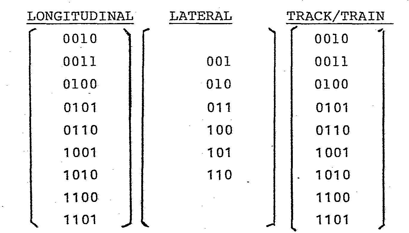
- A further limitation on the number of data words allowable is the requirement that neither the start sequence nor the data word itself must be repeated elsewhere within a message. The number of data words found allowable after the application of this requirement will, of course, depend on how the parity bits of the (16, 11) hamming code are derived since unwanted repetition of the start sequence or data word may involve these parity bits.
- The hamming code parity bits.are generated using a generator matrix G such that


order 11 and P is a (11 x 5) matrix with no row identically zero and all rows distinct. With P of the following form:four hundred and seven different data words are valid.
- The receiver unit of the equipment is shown in Figure 4 and comprises a receiver section interfacing via analogue to
digital converters 40 with a duplicated microprocessor arrangement of substantially the same configuration as that of the transmitter unit. The receiver section of the receiver unit comprises aninput transformer 41 arranged to receive the track-circuit signal picked up from the running rails of the track by theunit 3 of the track-circuit equipment. The received signal which is of frequency f ± Δf is fed viapreamplifier 42 to amixer 43 where it is mixed with a signal of frequency (f1 - fi) derived from alocal oscillator 44. Thelocal oscillator 44 is provided withfrequency selection inputs 45 which are preset in dependence on the centre frequency of the track circuit transmitter unit (in the present case, frequency f1). The output of themixer 43 is a signal of frequency fi ± Δf. Typically, the intermediate frequency fi is 75 Hz. - The purpose of heterodyning down the track-circuit signal to the intermediate frequency fi is to facilitate the selective filtering of the two frequencies making up the track-circuit signals, much lower Q filters being required to selectively detect the two frequencies (fi + Δf) and (fi -Δf) than the frequencies (f 1 +Δf ) and (f1 -Δf).
- The output of the
mixer 43 is fed toactive filters filters respective envelope detectors digital converters 40. Each analogue todigital converter 40 provides a two bit representation of the signal level at its input, this representation being fed over two pairs ofoutput lines - As already mentioned, the duplicated microprocessor arrangement of the receiving unit is of substantially the same form as that of the transmitter unit with each constituent microprocessor system comprising a
central processor unit 52, an I/O port 53, ROM and RAM memories 54 and 55, and anon-volatile memory 56 interfacing with the CPU via theport 53. Theelements 52 to 55 are preferably integrated on a single chip. - Each microprocessor system is fed via the
port 53 not only with the track-circuit signal strength information provided onlines line 58 from the upper of the two micrpproce.ssor systems as viewed in Figure 4, this output being used to control a standard track-circuit relay (not shown). The signal on theline 58 is also fed back to the two microprocessor systems in standard manner for such a duplicated microprocessor arrangement. - The fail-safe shut down of the microprocessor arrangement in the event of a disagreement being detected between the signals appearing on
line 58 and that internally provided by each of the two microprocessor systems, is effected by a redundancy management andpower supply unit 60 operating in standard manner. Shut down is similarly initiated if cross checking between the microprocessor systems,effected via lines 34, indicates a discrepancy either in intermediate results or programmes. - Each microprocessor system effects, under programme control, the following functions;
- 1) recognition of the presence of the frequencies (f 1 + Δf) and (f -Δf) in dependence on the signals fed thereto via the
lines - 2) checking that a transition between the two track-circuit signal frequencies (when the track circuit signal is detected) occurs at least every 0.2 seconds except during the parity portion of a message - the absence of such a transition is used to invalidate any message currently being received and possibly also to generate an error output signal and a "track occupied" signal;
- 3) checking that only one of the two track-circuit signal frequencies is received at any one time - the simultaneous receipt of both signal frequencies indicates the presence of crosstalk and a corresponding error signal can be generated to indicate this condition;
- 4) detection of the message start sequence whereby to identify the start of the
data word portion 38 andparity portion 39; - 5) reading of the
data word 38 contained in each message with frequency (f1 + Δf) being read as a binary "1" and frequency (f1 -Δf) being read as binary "0"; error detection and possible correction using theparity portion 39 of the message; 6) comparison of the first two bit-groups of the received data word with the local code set in via thelines 57; - 7) generation of a "track clear" signal on the
line 58 upon the received transmitter-identifying data corresponding to the local code setting - where the received and local codes do not correspond, possible generation of a "track occupied" signal and a corresponding error signal; - 8) generation of a "track occupied" signal on
line 58 in the absence of any track-circuit signal frequency for more than 0.1 second. - The error detection/correction process referred to in (5) above involves forming the error syndrome S of the received data word R in accordance with the following relation:


- For single errors, the value of S gives the exact digit in error by comparing the value of S with the rows of. HT. Double errors are detected but cannot be corrected. The (16,11) hamming code will, by itself, sometimes incorrectly decode triple errors; however, by testing the modulo-2 parity bit, such triple-error conditions can be detected (but not corrected). Four or more errors may result in incorrect decoding.
- From the foregoing, it can be seen that the receiving unit will generate a "track clear" signal only when the identifying local code of the associated transmitter unit is correctly received as non-overlapping bursts of the two track-circuit frequencies concerned. In the presence of crosstalk from another track circuit operating at the same centre frequency, then either the two track-circuit signal frequencies will be present together or, as may be the case where the transmitter unit associated with the receiver unit has failed, the received identifying code will not correspond to that set in via the
lines 57; in either case, a "track clear" signal will not be generated. - As regards the track-to-train codes embedded in the track circuit signal, these are arranged to be decoded by train borne equipment similar to that of the track-circuit receiving unit (the track-circuit signal being inductively coupled to train borne pick up coils).
- Of course, instead of the final bit group of the
message data word 38 being applied track-to-train signalling, this bit group could be used for an alternative railway signalling function such as the transmission of status information between the transmitter and receiver of a track circuit (in this case, in addition to arelay output 58, each track-circuit receiver could be provided with a code output indicated by dashed lines 99 in Figure 4). - Various modifications to the described equipment can, of course, be made. Thus for example in the receiver unit a digital hererodyning technique can be used rather than the illustrated analogue arrangement; in this case, filtering could advantageously be effected digitally in known manner.
Claims (15)
1. A method of providing security against crosstalk between traction-immune railway track circuits disposed in the same locality, each track circuit being of the type comprising transmitter means (2) arranged to output a track-circuit signal frequency-shift-keyed between two frequencies, and associated receiver means (3) arranged to selectively receive signals at said two frequencies; characterised in that the method includes the steps of:
- impressing a multi-bit binary data word (38) onto the track-circuit signal output by the transmitter means (2) of each track circuit, each said data word serving to identify the corresponding transmitter means and being impressed onto the track circuit signal by effecting the frequency shift keying of the latter in dependence on the bit values of the data word; and
- for each track-circuit receiver means (3), detecting the data words impressed on a track-circuit signal received thereby, and enabling the generation of a "track clear" signal by the receiver means when the transmitter means identified by a detected data word is the transmitter means belonging to the same track circuit as said receiver means.
2. Track circuit equipment comprising a plurality of track circuits (TC1, TC2, TC3) disposed in the same locality and each including: transmitter means (2) for feeding an a.c. track circuit signal to the running rails (1) of a railway line and receiver means (3) for selectively receiving from the running rails (1) track-circuit signals frequency-shirt keyed between two frequencies (f l, f2),
characterised in that
the transmitter means include an encoder for encoding a predetermined multi-bit binary data word (38) onto the track-circuit signal by frequency shift keying the latter between two frequencies (fl, f2), said data word serving to identify the corresponding transmitter means, and
signal proceesing means are arranged to decode track-circuit signals received by the receiver means whereby to detect binary data words encoded thereon and to generate a "track clear" output signal when the transmitter means identified by a detected data word is the transmitter means belonging to the same track circuit as the receiver means.
3. Track circuit equipment according to Claim 2, characterised in that the transmitter means of each track circuit is arranged to impress any selected one of a plurality of data words (38) onto the track-circuit signal output thereby, each data word of said plurality serving both to identify the transmitter means and to represent a different respective command or status code associated with a railway-signalling function additional to the track-circuit identification function, the receiver means of each track circuit being arranged to generate a "track clear" output signal upon detection of any one of the data words associated with the transmitter means belonging to the same track circuit as the receiver means.
4. Track circuit equipment according to Claim 3, characterised in that each data word (38) is divided into two parts one of which serves to identify the corresponding track-circuit transmitter means, and the other of which serves to represent said selected command or status code.
5. Track circuit equipment according to Claim 2, characterised in that the FSK modulation rate is equal to or less than 20 Hz.
6. Track circuit equipment according to Claim 2, characterised in that each data word (38) is included in an overall binary message that is impressed by the corresponding transmitter means (2) on its track circuit signal by frequency shift keying, the message further comprising a start sequence (35) and a parity section (39).
7. Track circuit equipment according to Claim 6, characterised in that said start sequence is a pseudo-random binary sequence.
8. Track circuit equipment according to Claim 6 or Claim 7, characterised in that each data word comprises respective bit groups identifying the lateral and longitudinal track location of the corresponding track-circuit transmitter means.
9. Track circuit equipment according to Claim 8, characterised in that each data word further comprises a bit group identifying a status or command code relating to a railway signalling function additional to the track circuit identification function.
10. Track circuit equipment according to any one of Claims 6 to 9, characterised in that said parity section comprises both a bit group that forms, together with the data word, a hamming codeword, and a modulo-2 parity bit.
11. Track circuit equipment according to any one of Claims 6 to 10, characterised in that the messages are such that a change in bit value occurs at least every X bits over at least a predetermined portion of each message where X is an integer less than the number of bits in the data word.
12. Track circuit equipment according to any one of Claims 6 to 11, characterised in that the messages are such that the data word of a message is not repeated elsewhere in the message.
13. A railway signalling method characterised in that rail-carried track-circuit signals are encoded both for the purpose of uniquely identifying each track-circuit transmitter to its corresponding receiver and for the purpose of transmitting a desired one of a predetermined repertoire of signal messages associated with an auxiliary signalling function, said method including the step of modulating the transmissions of each track-circuit transmitter with a selected one of a plurality of binary data words (38) each unique to that transmitter, the identity of the selected data word within said plurality being dependent on the identity of the said signal message it is desired to transmit whereby each said signal message is uniquely represented by a set of data words each of which belongs to a different said plurality and carried by the transmissions of a respective track-circuit transmitter.
14. A railway signalling method according to Claim 13, characterised in that each data word is structured such that it includes a portion uniquely identifying each auxiliary signal message.
15. A railway signalling method according to Claim 13 or Claim 14, characterised in that said auxiliary signalling function is track-to-train signalling.
Applications Claiming Priority (2)
| Application Number | Priority Date | Filing Date | Title |
|---|---|---|---|
| GB8415025 | 1984-06-13 | ||
| GB848415025A GB8415025D0 (en) | 1984-06-13 | 1984-06-13 | Railway track circuit equipment |
Publications (2)
| Publication Number | Publication Date |
|---|---|
| EP0165048A2 true EP0165048A2 (en) | 1985-12-18 |
| EP0165048A3 EP0165048A3 (en) | 1988-11-09 |
Family
ID=10562346
Family Applications (1)
| Application Number | Title | Priority Date | Filing Date |
|---|---|---|---|
| EP85304144A Withdrawn EP0165048A3 (en) | 1984-06-13 | 1985-06-12 | Railway track circuit equipment |
Country Status (5)
| Country | Link |
|---|---|
| EP (1) | EP0165048A3 (en) |
| AU (1) | AU4362185A (en) |
| DE (1) | DE165048T1 (en) |
| GB (1) | GB8415025D0 (en) |
| ZA (1) | ZA854411B (en) |
Cited By (9)
| Publication number | Priority date | Publication date | Assignee | Title |
|---|---|---|---|---|
| EP0878373A2 (en) * | 1997-05-15 | 1998-11-18 | Hitachi, Ltd. | Train detection system and method |
| EP1314627A2 (en) * | 2001-11-21 | 2003-05-28 | Westinghouse Brake And Signal Holdings Limited | Railway track circuits |
| US8297558B2 (en) | 2010-03-17 | 2012-10-30 | Safetran Systems Corporation | Crossing predictor with authorized track speed input |
| US8500071B2 (en) | 2009-10-27 | 2013-08-06 | Invensys Rail Corporation | Method and apparatus for bi-directional downstream adjacent crossing signaling |
| US8590844B2 (en) | 2009-07-17 | 2013-11-26 | Siemens Rail Auotmation Corporation | Track circuit communications |
| US8660215B2 (en) | 2010-03-16 | 2014-02-25 | Siemens Rail Automation Corporation | Decoding algorithm for frequency shift key communications |
| WO2015011529A1 (en) * | 2013-07-26 | 2015-01-29 | Alstom Transport Technologies | Track circuit mechanical joint integrity checker |
| WO2015019129A1 (en) * | 2013-08-09 | 2015-02-12 | Alstom Transport Technologies | Track circuit power supply vital monitor |
| CN114802368A (en) * | 2022-04-14 | 2022-07-29 | 通号城市轨道交通技术有限公司 | Equipment control method, system, device, equipment and storage medium of interlocking system |
Citations (4)
| Publication number | Priority date | Publication date | Assignee | Title |
|---|---|---|---|---|
| US3526278A (en) * | 1968-04-16 | 1970-09-01 | Byron Jackson Inc | High volume main valve for formation testers |
| US3666217A (en) * | 1970-05-04 | 1972-05-30 | Gen Signal Corp | Track communication system for continuous rail |
| US3829682A (en) * | 1971-01-11 | 1974-08-13 | Erico Prod Inc | Pulse coded railway signal system |
| GB2159311A (en) * | 1984-05-24 | 1985-11-27 | Westinghouse Brake & Signal | Vehicle protection system |
-
1984
- 1984-06-13 GB GB848415025A patent/GB8415025D0/en active Pending
-
1985
- 1985-06-12 ZA ZA854411A patent/ZA854411B/en unknown
- 1985-06-12 AU AU43621/85A patent/AU4362185A/en not_active Abandoned
- 1985-06-12 EP EP85304144A patent/EP0165048A3/en not_active Withdrawn
- 1985-06-12 DE DE198585304144T patent/DE165048T1/en active Pending
Patent Citations (4)
| Publication number | Priority date | Publication date | Assignee | Title |
|---|---|---|---|---|
| US3526278A (en) * | 1968-04-16 | 1970-09-01 | Byron Jackson Inc | High volume main valve for formation testers |
| US3666217A (en) * | 1970-05-04 | 1972-05-30 | Gen Signal Corp | Track communication system for continuous rail |
| US3829682A (en) * | 1971-01-11 | 1974-08-13 | Erico Prod Inc | Pulse coded railway signal system |
| GB2159311A (en) * | 1984-05-24 | 1985-11-27 | Westinghouse Brake & Signal | Vehicle protection system |
Cited By (26)
| Publication number | Priority date | Publication date | Assignee | Title |
|---|---|---|---|---|
| US7027901B2 (en) | 1997-05-15 | 2006-04-11 | Hitachi, Ltd. | Transmitter and receiver device for train detection |
| US6317664B2 (en) | 1997-05-15 | 2001-11-13 | Hitachi, Ltd. | Train detection system and a train detection method |
| US7200470B2 (en) | 1997-05-15 | 2007-04-03 | Hitachi, Ltd. | Train detection system and a train detection method |
| EP0878373A2 (en) * | 1997-05-15 | 1998-11-18 | Hitachi, Ltd. | Train detection system and method |
| US6470244B2 (en) | 1997-05-15 | 2002-10-22 | Hitachi, Ltd. | Train detection system |
| EP0878373A3 (en) * | 1997-05-15 | 2000-08-02 | Hitachi, Ltd. | Train detection system and method |
| US6604031B2 (en) | 1997-05-15 | 2003-08-05 | Hitachi, Ltd. | Train detection system and a train detection method |
| US6829526B2 (en) | 1997-05-15 | 2004-12-07 | Hitachi, Ltd. | Train detection system and a train detection method cross reference to related application |
| EP1535818A2 (en) * | 1997-05-15 | 2005-06-01 | Hitachi, Ltd. | A transmitter/receiver for train detection |
| EP1535818A3 (en) * | 1997-05-15 | 2005-11-16 | Hitachi, Ltd. | A transmitter/receiver for train detection |
| EP1314627A3 (en) * | 2001-11-21 | 2003-06-04 | Westinghouse Brake And Signal Holdings Limited | Railway track circuits |
| EP1314627A2 (en) * | 2001-11-21 | 2003-05-28 | Westinghouse Brake And Signal Holdings Limited | Railway track circuits |
| US7017864B2 (en) | 2001-11-21 | 2006-03-28 | Westinghouse Brake And Signal Holdings Limited | Railway track circuits |
| SG112855A1 (en) * | 2001-11-21 | 2005-07-28 | Westinghouse Brake & Signal | Railway track circuits |
| US8590844B2 (en) | 2009-07-17 | 2013-11-26 | Siemens Rail Auotmation Corporation | Track circuit communications |
| US9248849B2 (en) | 2009-10-27 | 2016-02-02 | Siemens Industry, Inc. | Apparatus for bi-directional downstream adjacent crossing signaling |
| US8500071B2 (en) | 2009-10-27 | 2013-08-06 | Invensys Rail Corporation | Method and apparatus for bi-directional downstream adjacent crossing signaling |
| US8660215B2 (en) | 2010-03-16 | 2014-02-25 | Siemens Rail Automation Corporation | Decoding algorithm for frequency shift key communications |
| US8297558B2 (en) | 2010-03-17 | 2012-10-30 | Safetran Systems Corporation | Crossing predictor with authorized track speed input |
| WO2015011529A1 (en) * | 2013-07-26 | 2015-01-29 | Alstom Transport Technologies | Track circuit mechanical joint integrity checker |
| US10093329B2 (en) | 2013-07-26 | 2018-10-09 | Alstom Transport Technologies | Track circuit mechanical joint integrity checker |
| WO2015019129A1 (en) * | 2013-08-09 | 2015-02-12 | Alstom Transport Technologies | Track circuit power supply vital monitor |
| US9821823B2 (en) | 2013-08-09 | 2017-11-21 | Alstom Transport Technologies | Track circuit power supply vital monitor |
| AU2013397474B2 (en) * | 2013-08-09 | 2019-08-29 | Alstom Transport Technologies | Track circuit power supply vital monitor |
| CN114802368B (en) * | 2022-04-14 | 2023-09-26 | 通号城市轨道交通技术有限公司 | Device control method, system, device, equipment and storage medium of interlocking system |
| CN114802368A (en) * | 2022-04-14 | 2022-07-29 | 通号城市轨道交通技术有限公司 | Equipment control method, system, device, equipment and storage medium of interlocking system |
Also Published As
| Publication number | Publication date |
|---|---|
| EP0165048A3 (en) | 1988-11-09 |
| DE165048T1 (en) | 1986-05-22 |
| ZA854411B (en) | 1986-03-26 |
| AU4362185A (en) | 1985-12-19 |
| GB8415025D0 (en) | 1984-07-18 |
Similar Documents
| Publication | Publication Date | Title |
|---|---|---|
| US4494717A (en) | Vital transmission checking apparatus for communication channels | |
| US7200470B2 (en) | Train detection system and a train detection method | |
| US4619425A (en) | Pulse code system for railroad track circuits | |
| US4456997A (en) | Facility for fail-safe data transmission between trackside equipment of a guideway and vehicles moving therealong | |
| US4447903A (en) | Forward error correction using coding and redundant transmission | |
| US4787581A (en) | Train detection system operating in accordance with the axle-counting principle | |
| US20110309204A1 (en) | Device for detecting the occupied state and the free state of a track section as well as method for operating such a device | |
| US4320881A (en) | Fail-safe decoder for digital track circuits | |
| EP0165048A2 (en) | Railway track circuit equipment | |
| EP0015730A1 (en) | A data transmission system, and a method of passing data through a data transmission system | |
| US3811112A (en) | Control command security in binary remote control | |
| US4628309A (en) | System and device for remote surveillance of equipment on a digital transmission link without interrupting traffic | |
| EP0513129B1 (en) | Track circuit system | |
| US3794977A (en) | A multiplex control system for controlling the operation of a plurality of stations | |
| EP0738973B1 (en) | Data transfer method and device | |
| GB2049365A (en) | Data transmission system | |
| Hill | Optimal construction of synchronizable coding for railway track circuit data transmission | |
| GB2159994A (en) | Vehicle speed control | |
| Adadurov et al. | ACCURACY OF VITAL MESSAGES TRANSMISSIOM USING THRESHOLD FRAGMENTATION METHODS AND ANTINOISE CODING | |
| JPH0229256B2 (en) | ||
| JPH01278138A (en) | Frame synchronizing system |
Legal Events
| Date | Code | Title | Description |
|---|---|---|---|
| PUAI | Public reference made under article 153(3) epc to a published international application that has entered the european phase |
Free format text: ORIGINAL CODE: 0009012 |
|
| AK | Designated contracting states |
Designated state(s): DE FR GB IT SE |
|
| ITCL | It: translation for ep claims filed |
Representative=s name: JACOBACCI CASETTA & PERANI S.P.A. |
|
| EL | Fr: translation of claims filed | ||
| DET | De: translation of patent claims | ||
| PUAL | Search report despatched |
Free format text: ORIGINAL CODE: 0009013 |
|
| AK | Designated contracting states |
Kind code of ref document: A3 Designated state(s): DE FR GB IT SE |
|
| STAA | Information on the status of an ep patent application or granted ep patent |
Free format text: STATUS: THE APPLICATION IS DEEMED TO BE WITHDRAWN |
|
| 18D | Application deemed to be withdrawn |
Effective date: 19890101 |
|
| RIN1 | Information on inventor provided before grant (corrected) |
Inventor name: CROSS, PETER JOHN |