EP0164892A1 - Horizontal furnace apparatus - Google Patents
Horizontal furnace apparatus Download PDFInfo
- Publication number
- EP0164892A1 EP0164892A1 EP85303270A EP85303270A EP0164892A1 EP 0164892 A1 EP0164892 A1 EP 0164892A1 EP 85303270 A EP85303270 A EP 85303270A EP 85303270 A EP85303270 A EP 85303270A EP 0164892 A1 EP0164892 A1 EP 0164892A1
- Authority
- EP
- European Patent Office
- Prior art keywords
- zone
- furnace
- furnace tube
- cantilever
- suspension
- Prior art date
- Legal status (The legal status is an assumption and is not a legal conclusion. Google has not performed a legal analysis and makes no representation as to the accuracy of the status listed.)
- Granted
Links
- 238000010438 heat treatment Methods 0.000 claims abstract description 49
- 239000000725 suspension Substances 0.000 claims abstract description 48
- 238000012545 processing Methods 0.000 claims abstract description 18
- VYPSYNLAJGMNEJ-UHFFFAOYSA-N silicon dioxide Inorganic materials O=[Si]=O VYPSYNLAJGMNEJ-UHFFFAOYSA-N 0.000 claims description 18
- 239000010453 quartz Substances 0.000 claims description 17
- 239000004065 semiconductor Substances 0.000 abstract description 8
- 235000012431 wafers Nutrition 0.000 description 28
- 239000000463 material Substances 0.000 description 6
- 238000000034 method Methods 0.000 description 5
- 239000007789 gas Substances 0.000 description 4
- 238000004519 manufacturing process Methods 0.000 description 4
- PNEYBMLMFCGWSK-UHFFFAOYSA-N aluminium oxide Inorganic materials [O-2].[O-2].[O-2].[Al+3].[Al+3] PNEYBMLMFCGWSK-UHFFFAOYSA-N 0.000 description 3
- 230000015572 biosynthetic process Effects 0.000 description 3
- 238000005229 chemical vapour deposition Methods 0.000 description 3
- 238000002474 experimental method Methods 0.000 description 3
- IJGRMHOSHXDMSA-UHFFFAOYSA-N Atomic nitrogen Chemical compound N#N IJGRMHOSHXDMSA-UHFFFAOYSA-N 0.000 description 2
- 238000009792 diffusion process Methods 0.000 description 2
- 238000009826 distribution Methods 0.000 description 2
- 230000005489 elastic deformation Effects 0.000 description 2
- 230000035939 shock Effects 0.000 description 2
- 229910052581 Si3N4 Inorganic materials 0.000 description 1
- 230000004323 axial length Effects 0.000 description 1
- 238000005452 bending Methods 0.000 description 1
- 239000000919 ceramic Substances 0.000 description 1
- 238000001311 chemical methods and process Methods 0.000 description 1
- 230000003749 cleanliness Effects 0.000 description 1
- 238000004891 communication Methods 0.000 description 1
- 239000000428 dust Substances 0.000 description 1
- 239000005350 fused silica glass Substances 0.000 description 1
- 239000012774 insulation material Substances 0.000 description 1
- 238000005304 joining Methods 0.000 description 1
- 238000012986 modification Methods 0.000 description 1
- 230000004048 modification Effects 0.000 description 1
- 229910052757 nitrogen Inorganic materials 0.000 description 1
- 230000003647 oxidation Effects 0.000 description 1
- 238000007254 oxidation reaction Methods 0.000 description 1
- 230000005855 radiation Effects 0.000 description 1
- HBMJWWWQQXIZIP-UHFFFAOYSA-N silicon carbide Chemical compound [Si+]#[C-] HBMJWWWQQXIZIP-UHFFFAOYSA-N 0.000 description 1
- 229910010271 silicon carbide Inorganic materials 0.000 description 1
- HQVNEWCFYHHQES-UHFFFAOYSA-N silicon nitride Chemical compound N12[Si]34N5[Si]62N3[Si]51N64 HQVNEWCFYHHQES-UHFFFAOYSA-N 0.000 description 1
- 230000002459 sustained effect Effects 0.000 description 1
- 238000012546 transfer Methods 0.000 description 1
- 238000011282 treatment Methods 0.000 description 1
Images

Classifications
-
- H—ELECTRICITY
- H01—ELECTRIC ELEMENTS
- H01L—SEMICONDUCTOR DEVICES NOT COVERED BY CLASS H10
- H01L21/00—Processes or apparatus adapted for the manufacture or treatment of semiconductor or solid state devices or of parts thereof
- H01L21/67—Apparatus specially adapted for handling semiconductor or electric solid state devices during manufacture or treatment thereof; Apparatus specially adapted for handling wafers during manufacture or treatment of semiconductor or electric solid state devices or components ; Apparatus not specifically provided for elsewhere
- H01L21/677—Apparatus specially adapted for handling semiconductor or electric solid state devices during manufacture or treatment thereof; Apparatus specially adapted for handling wafers during manufacture or treatment of semiconductor or electric solid state devices or components ; Apparatus not specifically provided for elsewhere for conveying, e.g. between different workstations
- H01L21/67739—Apparatus specially adapted for handling semiconductor or electric solid state devices during manufacture or treatment thereof; Apparatus specially adapted for handling wafers during manufacture or treatment of semiconductor or electric solid state devices or components ; Apparatus not specifically provided for elsewhere for conveying, e.g. between different workstations into and out of processing chamber
- H01L21/67754—Apparatus specially adapted for handling semiconductor or electric solid state devices during manufacture or treatment thereof; Apparatus specially adapted for handling wafers during manufacture or treatment of semiconductor or electric solid state devices or components ; Apparatus not specifically provided for elsewhere for conveying, e.g. between different workstations into and out of processing chamber horizontal transfer of a batch of workpieces
-
- H—ELECTRICITY
- H10—SEMICONDUCTOR DEVICES; ELECTRIC SOLID-STATE DEVICES NOT OTHERWISE PROVIDED FOR
- H10K—ORGANIC ELECTRIC SOLID-STATE DEVICES
- H10K71/00—Manufacture or treatment specially adapted for the organic devices covered by this subclass
-
- Y—GENERAL TAGGING OF NEW TECHNOLOGICAL DEVELOPMENTS; GENERAL TAGGING OF CROSS-SECTIONAL TECHNOLOGIES SPANNING OVER SEVERAL SECTIONS OF THE IPC; TECHNICAL SUBJECTS COVERED BY FORMER USPC CROSS-REFERENCE ART COLLECTIONS [XRACs] AND DIGESTS
- Y10—TECHNICAL SUBJECTS COVERED BY FORMER USPC
- Y10S—TECHNICAL SUBJECTS COVERED BY FORMER USPC CROSS-REFERENCE ART COLLECTIONS [XRACs] AND DIGESTS
- Y10S414/00—Material or article handling
- Y10S414/135—Associated with semiconductor wafer handling
- Y10S414/14—Wafer cassette transporting
Definitions
- the present invention relates to horizontal furnace apparatus, for instance for processing semiconductor devices such as semiconductor integrated circuits (IC).
- semiconductor devices such as semiconductor integrated circuits (IC).
- Heat treatment temperatures may be rather high, in excess of 1000 0 C.
- the major furnace type employed currently in IC mass-production lines is a horizontal furnace type. In order to improve productivity and reliability of heat treatments, large heat-treatment capacity, uniform temperature distribution and dust-free cleanliness are indispensible requirements of a horizontal furnace.
- a vertical furnace type has been used recently, but is still in the minority.
- a dust-free system is essential for the production of semiconductor devices.
- dust mainly comprising particulates generated by friction between quartz boats and a quartz furnace tube during loading and unloading of wafers into the furnace.
- the particulates are mainly of quartz, being derived from wear generated by the quartz-to-quartz friction between quartz-wares; boats and furnace tubes, etc.
- residual materials deposited on the inner wall of the quartz furnace tube during heat treatments for CVD processes, for instance are scraped to create particulates of associated materials.
- Fig.l is a cross-sectional view of a previously proposed horizontal furnace, schematically illustrating the structure of the furnace and aspects of loading of wafers to be heat treated.
- Wafers A are stacked in several quartz baskets B and accommodated on a quartz boat C.
- the wafers A are loaded into the furnace by pushing the boat C into furnace tube 1 in the direction of an arrow a, using a quartz bar 4 having a hooking notch at its end.
- the wafers A are unloaded by pulling the quartz boat C out of the tube 1 with the bar 4.
- the inlet of the furnace tube 1 is covered by a quartz cap 2.
- Furnace gas such as nitrogen is introduced by a gas inlet pipe la, flows through the tube 1 and flows out through an outlet pipe lb.
- the furnace tube 1 has heaters 3, shown by chain lines in Fig.l, disposed outside the furnace tube wall , and is surrounded by a layer of heat insulation material (not shown) such as alumina.
- a temperature equalizing tube (not shown) of high thermal conductivity ceramic is arranged outside the tube 1 to obtain a uniform axial temperature distribution.
- a suspension cantilever loading system wherein wafers stacked in baskets are sustained (suspended) inside the furnace tube during all the stages of a heating process: loading, unloading and heat processing.
- the wafers, baskets and suspension means never touch the inner wall of the furnace tube, eliminating the generation of particulates.
- Fig.2 is a cross-sectional view of a proposed horizontal furnace apparatus having a suspension cantilever loading system, taken along the axis of the furnace tube, illustrating schematically the structure of the furnace.
- a suspension cantilever 14 For loading wafers A into, or unloading them from, the horizontal furnace, a suspension cantilever 14, carrying baskets B stacked with wafers A, is pushed forward into or pulled out from the center of the furnace tube 1 by a cantilever drive mechanism 15.
- the upper portion of the cantilever 14 has a boat-like shape suitable for accommodating the baskets B.
- a cap 12 of the furnace tube 1 has a special opening 12a allowing the passage of a supporting portion of the cantilever.
- Fig.3 is a perspective view of a suspension cantilever system of the horizontal furnace apparatus of Fig.2.
- Automatically controlling the operation of the cantilever drive mechanism 15, the loading and unloading of the wafers A can be performed according to a predetermined schedule to reduce undesirable thermal shock to the wafers, which might cause damage to the wafers.
- contact-free loading and unloading with regard to the inner wall of the tube 1 can be completely realised by the above suspension cantilever system, a problem of deformation of the cantilever 14 arises during high temperature heat treatment.
- a few supports of heat-resistive material such as pure alumina (A1 2 0 3 ) or high-grade silicon carbide are used.
- the supports are sheathed with pure fused quartz so as to be easily cleaned.
- a "soft-landing", that is, descending vertically without any shock, of the baskets B onto the inner wall of the tube 1 during the heat processing can be effected by controlling the cantilever driver 15. After soft-landing of the baskets B, the cantilever 14 is retracted from the furnace tube 1 so as not to be exposed to heating.
- this requires a more complicated mechanism for the driver 15, and essentially contact between the baskets B and the inner wall of the furnace tube 1 still generates particulates.
- horizontal furnace apparatus comprising a furnace tube, heater means and suspension cantilever means movable in directions parallel to the longitudinal axis of the furnace tube,
- An embodiment of the present invention provides horizontal furnace apparatus for example for semiconductor fabrication processes, being capable of or more nearly capable of dust-free or particulates-free operation during loading, unloading and heat processing of workpieces such as semiconductor wafers.
- An embodiment of the present invention provides a high temperature horizontal furnace apparatus having a suspension cantilever which suspends workpieces, such as wafers, in a furnace tube during all stages of the process: loading, unloading and processing of the workpieces.
- An embodiment of the present invention provides horizontal furnace apparatus having a suspension cantilever system for loading and unloading of wafers, with a cantilever so structured as to prevent or more nearly prevent deformation of the cantilever during high temperature heat treatment of workpieces.
- a suspension cantilever in accordance with an embodiment of the present invention comprises a boat-like portion for accommodating workpieces, such as wafers, which is to be exposed to a high temperature during heat processing of the workpieces in the horizontal furnace in accordance with the embodiment, and a rigid supporting rod which during heat processing is positioned in a space of a relatively lower temperature provided in the furnace, so that it retains high rigidity during heat processing.
- the boat-like portion for accommodating thereon workpieces, e.g. wafers placed in baskets is supported by the rigid supporting rod for example through stays (a connecting portion of the cantilever) connecting the boat-like portion and the supporting rod .
- the whole cantilever is made of quartz.
- the suspension cantilever is driven to move forward and backward (into and out of the furnace) by a drive mechanism following a predetermined schedule.
- the horizontal furnace apparatus of the embodiment has a furnace tube having a cross-sectional profile such as to allow the passage of the suspension cantilever.
- the furnace tube comprises a heating room for heating the workpieces (e.g.
- the boat-like portion heated by heaters embedded outside the heating room of furnace tube; a supporting room for the supporting rod which is kept at relatively lower temperatures, suitable to maintain the strength of the material of the supporting rod; and a connecting room connecting the heating and supporting rooms over the full length in the axial direction of the heating and supporting rooms, so as to allow the passage of the stays of the cantilever.
- the heating room, the connecting room and the supporting room are positioned vertically one below another in the recited order.
- a suspension cantilever differing from that of Figs.2 and 3 is employed.
- the suspension cantilever of the embodiment is shown in the perspective view of Fig.4. It comprises an accommodating portion 24a, a supporting portion 24b and connecting portion 24c.
- the whole cantilever is of quartz.
- other materials such as alumina or silicon nitride may be employed for the supporting portion to provide the cantilever with greater strength.
- the accommodating portion has a boat-like shape, a rectangular tray having a straight generatrix in a longitudinal direction thereof, and a circular arc cross-section in the perpendicular direction, suitable to accommodate workpieces (for instance suitable to accommodate baskets B containing semiconductor wafers A).
- the supporting portion 24b is a rigid supporting rod suspended by a suspension cantilever driver 25.
- the accommodating portion 24a and the supporting rod 24b are connected to each other by the connecting portion 24c, which has a stay structure as shown in Fig.4. Center planes of the three portions 24a, 24b and 24c are essentially in the same vertical plane.
- an embodiment of the invention employs a horizontal furnace having a cross-sectional profile which permits passage of the suspension cantilever into and out of the furnace.
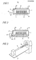
- Fig.5(a) is as schematic cross-sectional view taken along the axis of the furnace tube of a horizontal furnace in accordance with an embodiment of the present invention
- Fig.5(b) is a schematic cross-sectional view taken perpendicularly of the axis of the horizontal furnace tube.
- the furnace tube 21 of the horizontal furnace comprises a heating chamber or zone 27 and a support chamber or zone 25 arranged in parallel to one another.
- the heating chamber or zone 27 is located above the support chamber or zone 25.
- the heating chamber 27 is heated by heaters 23, whose elements are arranged longitudinally on the exterior of the heating chamber 27.
- the support chamber 25 has relatively small diameter, as seen in Fig.5(b), sufficient to allow the supporting rod 24b to move in axial directions thereof without contacting internal walls bounding the chamber 25.
- the support chamber 25 has no heating means, so as to be kept at a lower temperature than the heating chamber 27 during a heating operation.
- the cross-sectional profile of the connecting zone 26 is roughly a rectangle, allowing the passage of the stays 24c of the suspension cantilever 24.
- the total profile of the cross-section of the tube of the horizontal furnace in accordance with the embodiment of the present invention is a rather complicated one as shown in Fig.5(b), but the strength of the suspension cantilever 24 is remarkably increased because it is substantially subjected only to a lower temperature in a heating operation, resulting in reduction of elastic deformation and non-detectable permanent deformation (creeping) of the cantilever after repeated operations at high temperature.
- the cantilever tested was of quartz, on which six baskets, stacked each with 25 6-inch wafers, were loaded. Heat treatment was performed at 1250°C (in the heating chamber) for 10 hours. The cantilever is suspended completely free from contact with internal wall surfaces of the furnace tube. The temperature of the supporting chamber was approximately 700°C. After ten such heat treatments, permanent deformation of the cantilever was not observed. Neither was contact observed between the cantilever and the furnace tube internal wall surfaces by the naked eye. Elastic deformation measured at the end of the cantilever, before and after the experiment, remained almost the same. Furthermore, after the heat treatments, residual particulates on the wafers were carefully checked using a mangifier of low magnification, and satisfactory results were obtained.
- the cross-sectional profile of the furnace tube is not confined to that shown in Fig.5(b).
- Any furnace tube profile can be used which permits the passage of a cantilever in accordance with an embodiment of the invention without contact between the cantilever and the furnace tube wall, and restricts heat transfer from a heating chamber or zone to a support chamber or zone by radiation and convection of furnace gas so that the temperature of the support chamber or zone is reduced.
- the relative positional arrangement of the heating chamber or zone and the supporting chamber or zone is not confined to the "vertical" arrangement as shown in Figs.5(a) and (b).
- Other relative positional arrangements of the two chambers or zones, such as a horizontal arrangement, are possible.
- the vertical arrangement is most suitable to maintain the support chamber or zone at a low temperature, because there occurs no upward heat convection by flow of furnace gas, and no bending moment around its longitudinal axis is applied to the connecting portion of the cantilever.
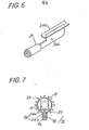
- Fig.6 is a perspective view of a suspension cantilever 34, in accordance with another embodiment of the present invention, which can be considered as a modification of the cantilever 24 of Fig.4, wherein the supporting portion 24b and connecting portion 24c are replaced by a combined supporting plate 34b which supports an accommodating portion 34a.
- Fig.7 is a cross-sectional view of the furnace tube of a furnace employed with the cantilever of Fig.6, in accordance with an embodiment of the present invention.
- the furnace tube 31 has a heating chamber or zone 37, and a combined support-connecting chamber or zone 35 of approximately rectangular cross-section.
- the overall cross-section of the furnace tube 31 is rather simpler than that of the furnace tube of Figs.5.
- a horizontal furnace which has a longitudinally extending main heating chamber or zone, into which workpieces are received for heat processing, which is provided with heating means for achieving a desired heat processing temperature, and a further chamber or zone, extending longitudinally alongside and in communication with the main heating chamber or zone, which is not provided with heating means and in which a lower temperature is achieved.
- the suspension cantilever has an accommodating portion, for carrying workpieces for heat processing and which, for heat processing, is received into the main heating chamber or zone from one longitudinal end of the main zone, and a further portion which, for heat processing, is received into the further chamber or zone from one longitudinal end of the further zone, so that the further portion is subject to the lower temperature.
- the further portion of the cantilever provides a supporting part of the cantilever and a connecting part, connecting the supporting part to the accommodating portion.
- the longitudinal axis of the accommodating portion is transversely separated from that of a supporting part of the cantilever, with the connecting part joining the accommodating portion and the supporting part together.
- the connecting part may be formed integrally with the supporting part, as in Fig.6, or they may be distinct parts, as in Figs.5.
Landscapes
- Engineering & Computer Science (AREA)
- Manufacturing & Machinery (AREA)
- Physics & Mathematics (AREA)
- Condensed Matter Physics & Semiconductors (AREA)
- General Physics & Mathematics (AREA)
- Computer Hardware Design (AREA)
- Microelectronics & Electronic Packaging (AREA)
- Power Engineering (AREA)
Abstract
Description
- The present invention relates to horizontal furnace apparatus, for instance for processing semiconductor devices such as semiconductor integrated circuits (IC).
- The fabrication of semiconductor devices, ICs for instance, involves a large number of physical and chemical processes, such as diffusion processes for the formation of doped diffusion regions in wafers, oxidation processes for the formation of oxide layers on wafers, chemical vapour deposition (CVD) processes for the formation of epitaxial layers, etc., including relevant heat treatments. Heat treatment temperatures may be rather high, in excess of 10000C. The major furnace type employed currently in IC mass-production lines is a horizontal furnace type. In order to improve productivity and reliability of heat treatments, large heat-treatment capacity, uniform temperature distribution and dust-free cleanliness are indispensible requirements of a horizontal furnace. A vertical furnace type has been used recently, but is still in the minority.
- Generally, a dust-free system is essential for the production of semiconductor devices. In this regard, with a horizontal furnace, there has been a problem of dust mainly comprising particulates generated by friction between quartz boats and a quartz furnace tube during loading and unloading of wafers into the furnace. The particulates are mainly of quartz, being derived from wear generated by the quartz-to-quartz friction between quartz-wares; boats and furnace tubes, etc. In addition, residual materials deposited on the inner wall of the quartz furnace tube during heat treatments for CVD processes, for instance, are scraped to create particulates of associated materials.
- Fig.l is a cross-sectional view of a previously proposed horizontal furnace, schematically illustrating the structure of the furnace and aspects of loading of wafers to be heat treated. Wafers A are stacked in several quartz baskets B and accommodated on a quartz boat C. The wafers A are loaded into the furnace by pushing the boat C into
furnace tube 1 in the direction of an arrow a, using a quartz bar 4 having a hooking notch at its end. Similarly, the wafers A are unloaded by pulling the quartz boat C out of thetube 1 with the bar 4. The inlet of thefurnace tube 1 is covered by aquartz cap 2. Furnace gas such as nitrogen is introduced by a gas inlet pipe la, flows through thetube 1 and flows out through an outlet pipe lb. - The
furnace tube 1 hasheaters 3, shown by chain lines in Fig.l, disposed outside the furnace tube wall , and is surrounded by a layer of heat insulation material (not shown) such as alumina. A temperature equalizing tube (not shown) of high thermal conductivity ceramic is arranged outside thetube 1 to obtain a uniform axial temperature distribution. With a horizontal furnace of this type, the generation of particulates is inevitable during loading and unloading of wafers as described above. In addition, sticking tends to occur between thequartz tube 1 and quartz boat C in a treatment at high temperature such as approximately 1100°C. - In order to eliminate the generation of particulates as described above, a suspension cantilever loading system is proposed, wherein wafers stacked in baskets are sustained (suspended) inside the furnace tube during all the stages of a heating process: loading, unloading and heat processing. With this system, the wafers, baskets and suspension means never touch the inner wall of the furnace tube, eliminating the generation of particulates.
- Fig.2 is a cross-sectional view of a proposed horizontal furnace apparatus having a suspension cantilever loading system, taken along the axis of the furnace tube, illustrating schematically the structure of the furnace.
- For loading wafers A into, or unloading them from, the horizontal furnace, a
suspension cantilever 14, carrying baskets B stacked with wafers A, is pushed forward into or pulled out from the center of thefurnace tube 1 by acantilever drive mechanism 15. The upper portion of thecantilever 14 has a boat-like shape suitable for accommodating the basketsB. A cap 12 of thefurnace tube 1 has a special opening 12a allowing the passage of a supporting portion of the cantilever. - Fig.3 is a perspective view of a suspension cantilever system of the horizontal furnace apparatus of Fig.2. Automatically controlling the operation of the
cantilever drive mechanism 15, the loading and unloading of the wafers A can be performed according to a predetermined schedule to reduce undesirable thermal shock to the wafers, which might cause damage to the wafers. Although contact-free loading and unloading with regard to the inner wall of thetube 1 can be completely realised by the above suspension cantilever system, a problem of deformation of thecantilever 14 arises during high temperature heat treatment. In order to minimize deformation of thesuspension cantilever 14, a few supports of heat-resistive material such as pure alumina (A1203) or high-grade silicon carbide are used. The supports are sheathed with pure fused quartz so as to be easily cleaned. However, there is a limit to the strength of these materials at high temperature. - To overcome the problem of high temperature deformation, a "soft-landing", that is, descending vertically without any shock, of the baskets B onto the inner wall of the
tube 1 during the heat processing can be effected by controlling thecantilever driver 15. After soft-landing of the baskets B, thecantilever 14 is retracted from thefurnace tube 1 so as not to be exposed to heating. However, this requires a more complicated mechanism for thedriver 15, and essentially contact between the baskets B and the inner wall of thefurnace tube 1 still generates particulates. - According to the present invention there is provided horizontal furnace apparatus, comprising a furnace tube, heater means and suspension cantilever means movable in directions parallel to the longitudinal axis of the furnace tube,
- the suspension cantilever means comprising an accommodating portion, for accommodating workpieces to be heat treated, a supporting portion, and a connecting portion connecting said accommodating portion and said supporting portion,
- the furnace tube comprising
- a heating chamber or zone, with the heater means arranged for heating that chamber or zone, for receiving the accommodating portion of the suspension cantilever means, with workpieces to be heat treated, and
- a further chamber or zone, extending longitudinally alongside the heating chamber or zone, for receiving the supporting portion of the suspension cantilever means,
- the furnace tube allowing passage of the suspension cantilever means for loading, heat processing and unloading of workpieces accommodated on the suspension cantilever means, resulting in the supporting portion of the suspension cantilever means being kept at a lower temperature than the temperature of the heating chamber or zone during a heating process.
- An embodiment of the present invention provides horizontal furnace apparatus for example for semiconductor fabrication processes, being capable of or more nearly capable of dust-free or particulates-free operation during loading, unloading and heat processing of workpieces such as semiconductor wafers.
- An embodiment of the present invention provides a high temperature horizontal furnace apparatus having a suspension cantilever which suspends workpieces, such as wafers, in a furnace tube during all stages of the process: loading, unloading and processing of the workpieces.
- An embodiment of the present invention provides horizontal furnace apparatus having a suspension cantilever system for loading and unloading of wafers, with a cantilever so structured as to prevent or more nearly prevent deformation of the cantilever during high temperature heat treatment of workpieces.
- To eliminate the above-mentioned drawbacks of a suspension cantilever system as previously employed, a suspension cantilever in accordance with an embodiment of the present invention comprises a boat-like portion for accommodating workpieces, such as wafers, which is to be exposed to a high temperature during heat processing of the workpieces in the horizontal furnace in accordance with the embodiment, and a rigid supporting rod which during heat processing is positioned in a space of a relatively lower temperature provided in the furnace, so that it retains high rigidity during heat processing. The boat-like portion for accommodating thereon workpieces, e.g. wafers placed in baskets, is supported by the rigid supporting rod for example through stays (a connecting portion of the cantilever) connecting the boat-like portion and the supporting rod . The whole cantilever is made of quartz. For heat processing workpieces, the suspension cantilever is driven to move forward and backward (into and out of the furnace) by a drive mechanism following a predetermined schedule. The horizontal furnace apparatus of the embodiment has a furnace tube having a cross-sectional profile such as to allow the passage of the suspension cantilever. The furnace tube comprises a heating room for heating the workpieces (e.g. wafers) and the boat-like portion, heated by heaters embedded outside the heating room of furnace tube; a supporting room for the supporting rod which is kept at relatively lower temperatures, suitable to maintain the strength of the material of the supporting rod; and a connecting room connecting the heating and supporting rooms over the full length in the axial direction of the heating and supporting rooms, so as to allow the passage of the stays of the cantilever. Usually, the heating room, the connecting room and the supporting room are positioned vertically one below another in the recited order.
- Reference is made, by way of example, to the accompanying drawings, in which:-
- Fig.l is a cross-sectional view of a previously proposed horizontal furnace, taken along the axis of the furnace tube, illustrating schematically the structure of the furnace tube with wafers loaded therein using a quartz boat,
- Fig.2 is a cross-sectional view of a proposed horizontal furnace, taken along the axis of the furnace tube, illustrating schematically the structure of the furnace tube, with wafers loaded therein, using a suspension cantilever loading system,
- Fig.3 is a perspective view illustrating the structure of a suspension cantilever as employed with the furnace of Fig.2,
- Fig.4 is a schematic perspective view illustrating the structure of an embodiment of the present invention, primarily illustrating a suspension cantilever thereof,
- Fig.5(a) is a cross-sectional view of an embodiment of the present invention, taken along the axis of the furnace tube thereof,
- Fig.5(b) is a cross-sectional view of the furnace of Fig.5(a) taken perpendicularly of the furnace tube axis, illustrating structure and loading of the furnace,
- Fig.6 is a perspective view illustrating a suspension cantilever of another embodiment of the present invention, which cantilever has a combined supporting and connecting portion, and
- Fig.7 is a cross-sectional view illustrating a furnace tube of the embodiment of the present invention which employs the suspension cantilever of Fig.6.
- For horizontal furnace apparatus embodying the present invention, a suspension cantilever differing from that of Figs.2 and 3 is employed. The suspension cantilever of the embodiment is shown in the perspective view of Fig.4. It comprises an
accommodating portion 24a, a supporting portion 24b and connecting portion 24c. The whole cantilever is of quartz. However, other materials such as alumina or silicon nitride may be employed for the supporting portion to provide the cantilever with greater strength. The accommodating portion has a boat-like shape, a rectangular tray having a straight generatrix in a longitudinal direction thereof, and a circular arc cross-section in the perpendicular direction, suitable to accommodate workpieces (for instance suitable to accommodate baskets B containing semiconductor wafers A). The supporting portion 24b is a rigid supporting rod suspended by asuspension cantilever driver 25. Theaccommodating portion 24a and the supporting rod 24b are connected to each other by the connecting portion 24c, which has a stay structure as shown in Fig.4. Center planes of the threeportions 24a, 24b and 24c are essentially in the same vertical plane. - In accord with the
suspension cantilever 24 as described above, an embodiment of the invention employs a horizontal furnace having a cross-sectional profile which permits passage of the suspension cantilever into and out of the furnace. Fig.5(a) is as schematic cross-sectional view taken along the axis of the furnace tube of a horizontal furnace in accordance with an embodiment of the present invention, and Fig.5(b) is a schematic cross-sectional view taken perpendicularly of the axis of the horizontal furnace tube. Thefurnace tube 21 of the horizontal furnace comprises a heating chamber orzone 27 and a support chamber orzone 25 arranged in parallel to one another. The heating chamber orzone 27 is located above the support chamber orzone 25. These chambers are connected by a connecting chamber ofzone 26 along the full axial length of the chambers. Theheating chamber 27 is heated byheaters 23, whose elements are arranged longitudinally on the exterior of theheating chamber 27. Thesupport chamber 25 has relatively small diameter, as seen in Fig.5(b), sufficient to allow the supporting rod 24b to move in axial directions thereof without contacting internal walls bounding thechamber 25. Thesupport chamber 25 has no heating means, so as to be kept at a lower temperature than theheating chamber 27 during a heating operation. The cross-sectional profile of the connectingzone 26 is roughly a rectangle, allowing the passage of the stays 24c of thesuspension cantilever 24. Thus, the total profile of the cross-section of the tube of the horizontal furnace in accordance with the embodiment of the present invention is a rather complicated one as shown in Fig.5(b), but the strength of thesuspension cantilever 24 is remarkably increased because it is substantially subjected only to a lower temperature in a heating operation, resulting in reduction of elastic deformation and non-detectable permanent deformation (creeping) of the cantilever after repeated operations at high temperature. - To investigate the increased high temperature strength of the cantilever, an experiment was conducted, and the results obtained by the inventor will be described. The cantilever tested was of quartz, on which six baskets, stacked each with 25 6-inch wafers, were loaded. Heat treatment was performed at 1250°C (in the heating chamber) for 10 hours. The cantilever is suspended completely free from contact with internal wall surfaces of the furnace tube. The temperature of the supporting chamber was approximately 700°C. After ten such heat treatments, permanent deformation of the cantilever was not observed. Neither was contact observed between the cantilever and the furnace tube internal wall surfaces by the naked eye. Elastic deformation measured at the end of the cantilever, before and after the experiment, remained almost the same. Furthermore, after the heat treatments, residual particulates on the wafers were carefully checked using a mangifier of low magnification, and satisfactory results were obtained.
- In the above experiments, wafers were loaded as the load weight, but it will be appreciated that the load placed in the furnace is not limited to wafers.
- In accordance with embodiments of the invention, the cross-sectional profile of the furnace tube is not confined to that shown in Fig.5(b). Any furnace tube profile can be used which permits the passage of a cantilever in accordance with an embodiment of the invention without contact between the cantilever and the furnace tube wall, and restricts heat transfer from a heating chamber or zone to a support chamber or zone by radiation and convection of furnace gas so that the temperature of the support chamber or zone is reduced. Further, the relative positional arrangement of the heating chamber or zone and the supporting chamber or zone is not confined to the "vertical" arrangement as shown in Figs.5(a) and (b). Other relative positional arrangements of the two chambers or zones, such as a horizontal arrangement, are possible. However, the vertical arrangement is most suitable to maintain the support chamber or zone at a low temperature, because there occurs no upward heat convection by flow of furnace gas, and no bending moment around its longitudinal axis is applied to the connecting portion of the cantilever.
- Fig.6 is a perspective view of a
suspension cantilever 34, in accordance with another embodiment of the present invention, which can be considered as a modification of thecantilever 24 of Fig.4, wherein the supporting portion 24b and connecting portion 24c are replaced by a combined supportingplate 34b which supports an accommodating portion 34a. Fig.7 is a cross-sectional view of the furnace tube of a furnace employed with the cantilever of Fig.6, in accordance with an embodiment of the present invention. In accordance with thesuspension cantilever 34, the furnace tube 31 has a heating chamber orzone 37, and a combined support-connecting chamber or zone 35 of approximately rectangular cross-section. The overall cross-section of the furnace tube 31 is rather simpler than that of the furnace tube of Figs.5. - In horizontal furnace apparatus embodying the present invention a horizontal furnace is provided which has a longitudinally extending main heating chamber or zone, into which workpieces are received for heat processing, which is provided with heating means for achieving a desired heat processing temperature, and a further chamber or zone, extending longitudinally alongside and in communication with the main heating chamber or zone, which is not provided with heating means and in which a lower temperature is achieved. The suspension cantilever has an accommodating portion, for carrying workpieces for heat processing and which, for heat processing, is received into the main heating chamber or zone from one longitudinal end of the main zone, and a further portion which, for heat processing, is received into the further chamber or zone from one longitudinal end of the further zone, so that the further portion is subject to the lower temperature.
- The further portion of the cantilever provides a supporting part of the cantilever and a connecting part, connecting the supporting part to the accommodating portion.
- The longitudinal axis of the accommodating portion is transversely separated from that of a supporting part of the cantilever, with the connecting part joining the accommodating portion and the supporting part together. The connecting part may be formed integrally with the supporting part, as in Fig.6, or they may be distinct parts, as in Figs.5.
Claims (7)
Applications Claiming Priority (2)
| Application Number | Priority Date | Filing Date | Title |
|---|---|---|---|
| JP59096983A JPS60240121A (en) | 1984-05-15 | 1984-05-15 | Horizontal-type oven |
| JP96983/84 | 1984-05-15 |
Publications (2)
| Publication Number | Publication Date |
|---|---|
| EP0164892A1 true EP0164892A1 (en) | 1985-12-18 |
| EP0164892B1 EP0164892B1 (en) | 1989-01-18 |
Family
ID=14179445
Family Applications (1)
| Application Number | Title | Priority Date | Filing Date |
|---|---|---|---|
| EP85303270A Expired EP0164892B1 (en) | 1984-05-15 | 1985-05-09 | Horizontal furnace apparatus |
Country Status (5)
| Country | Link |
|---|---|
| US (1) | US4613305A (en) |
| EP (1) | EP0164892B1 (en) |
| JP (1) | JPS60240121A (en) |
| KR (1) | KR900000835B1 (en) |
| DE (1) | DE3567769D1 (en) |
Families Citing this family (12)
| Publication number | Priority date | Publication date | Assignee | Title |
|---|---|---|---|---|
| US4692115A (en) * | 1985-04-03 | 1987-09-08 | Thermco Systems, Inc. | Semiconductor wafer furnace door |
| FR2594102B1 (en) * | 1986-02-12 | 1991-04-19 | Stein Heurtey | AUTOMATED FLEXIBLE INSTALLATION FOR FAST THERMOCHEMICAL TREATMENT |
| US4767251A (en) * | 1986-05-06 | 1988-08-30 | Amtech Systems, Inc. | Cantilever apparatus and method for loading wafer boats into cantilever diffusion tubes |
| US4761134B1 (en) * | 1987-03-30 | 1993-11-16 | Silicon carbide diffusion furnace components with an impervious coating thereon | |
| US4876225A (en) * | 1987-05-18 | 1989-10-24 | Berkeley Quartz Lab, Inc. | Cantilevered diffusion chamber atmospheric loading system and method |
| US4943235A (en) * | 1987-11-27 | 1990-07-24 | Tel Sagami Limited | Heat-treating apparatus |
| KR0139026B1 (en) * | 1988-02-05 | 1998-06-01 | 후세 노보루 | Heat-treating apparatus and a method for the same |
| US4976612A (en) * | 1989-06-20 | 1990-12-11 | Automated Wafer Systems | Purge tube with floating end cap for loading silicon wafers into a furnace |
| GB9010833D0 (en) * | 1990-05-15 | 1990-07-04 | Electrotech Research Limited | Workpiece support |
| US5174745A (en) * | 1990-12-03 | 1992-12-29 | Samsung Electronics Co., Ltd. | Impurity diffusing furnace |
| KR101424543B1 (en) * | 2010-06-04 | 2014-07-31 | 신에쓰 가가꾸 고교 가부시끼가이샤 | Heat-treatment furnace |
| US9018065B2 (en) * | 2012-05-08 | 2015-04-28 | Globalfoundries Inc. | Horizontal epitaxy furnace for channel SiGe formation |
Citations (3)
| Publication number | Priority date | Publication date | Assignee | Title |
|---|---|---|---|---|
| GB1160162A (en) * | 1967-01-02 | 1969-07-30 | Monsanto Co | Apparatus and method for production of Epitaxial Films |
| DE2524616A1 (en) * | 1975-06-03 | 1976-12-23 | Siemens Ag | Semiconductor chip thermal treatment device - has movable store in form of vehicle with two roller like wheels |
| DE2848691A1 (en) * | 1977-11-11 | 1979-05-17 | Dionex Corp | METHOD AND GAS FOR TREATMENT OF SEMICONDUCTOR COMPONENTS |
Family Cites Families (8)
| Publication number | Priority date | Publication date | Assignee | Title |
|---|---|---|---|---|
| US2754104A (en) * | 1951-10-05 | 1956-07-10 | Selas Corp Of America | Method and apparatus for heating ingots |
| US2656170A (en) * | 1951-11-16 | 1953-10-20 | Selas Corp Of America | Method and apparatus for heating objects |
| US3669431A (en) * | 1971-01-25 | 1972-06-13 | Signetics Corp | Boat pulling apparatus for diffusion furnace and method |
| US3723053A (en) * | 1971-10-26 | 1973-03-27 | Myers Platter S | Heat treating process for semiconductor fabrication |
| US4217095A (en) * | 1977-05-23 | 1980-08-12 | Tetsuya Tokitsu | Reheating furnace for use in a hot rolling line |
| JPS5843509A (en) * | 1981-09-09 | 1983-03-14 | Fuji Electric Corp Res & Dev Ltd | Mass-production type film fabricating device |
| JPS58218115A (en) * | 1982-06-14 | 1983-12-19 | Sony Corp | Heat treatment apparatus |
| US4461617A (en) * | 1982-10-25 | 1984-07-24 | Asq Boats, Inc. | Carrier for semiconductors |
-
1984
- 1984-05-15 JP JP59096983A patent/JPS60240121A/en active Granted
-
1985
- 1985-04-22 KR KR1019850002704A patent/KR900000835B1/en not_active IP Right Cessation
- 1985-05-09 DE DE8585303270T patent/DE3567769D1/en not_active Expired
- 1985-05-09 EP EP85303270A patent/EP0164892B1/en not_active Expired
- 1985-05-09 US US06/732,304 patent/US4613305A/en not_active Expired - Fee Related
Patent Citations (3)
| Publication number | Priority date | Publication date | Assignee | Title |
|---|---|---|---|---|
| GB1160162A (en) * | 1967-01-02 | 1969-07-30 | Monsanto Co | Apparatus and method for production of Epitaxial Films |
| DE2524616A1 (en) * | 1975-06-03 | 1976-12-23 | Siemens Ag | Semiconductor chip thermal treatment device - has movable store in form of vehicle with two roller like wheels |
| DE2848691A1 (en) * | 1977-11-11 | 1979-05-17 | Dionex Corp | METHOD AND GAS FOR TREATMENT OF SEMICONDUCTOR COMPONENTS |
Non-Patent Citations (2)
| Title |
|---|
| JOURNAL OF VACUUM SCIENCE & TECHNOLOGY, vol. 14, no. 5, Sept./Oct. 1977, New York. KERN et al. +Advances in deposition processes for passivation films" pages 1082-1099 * |
| RGA REVIEW, vol. 44, June 1983, OLSEN et al. "Double-Barrel III-V compound vapour-phase epitaxy systems" pages 270-286 * |
Also Published As
| Publication number | Publication date |
|---|---|
| JPS60240121A (en) | 1985-11-29 |
| JPH0520895B2 (en) | 1993-03-22 |
| EP0164892B1 (en) | 1989-01-18 |
| KR850008060A (en) | 1985-12-11 |
| US4613305A (en) | 1986-09-23 |
| KR900000835B1 (en) | 1990-02-17 |
| DE3567769D1 (en) | 1989-02-23 |
Similar Documents
| Publication | Publication Date | Title |
|---|---|---|
| US8476560B2 (en) | Thermal processing furnace | |
| EP0164892B1 (en) | Horizontal furnace apparatus | |
| KR100395994B1 (en) | Supporting boat of the object to be treated | |
| JP4174837B2 (en) | Vertical heat treatment furnace | |
| US5516283A (en) | Apparatus for processing a plurality of circular wafers | |
| EP0393809B1 (en) | Pressure resistant thermal reactor system for semiconductor processing | |
| KR0147046B1 (en) | Heating apparatus | |
| JP4971541B2 (en) | Method and apparatus for heat treatment of a semiconductor substrate | |
| US6099645A (en) | Vertical semiconductor wafer carrier with slats | |
| US6856078B2 (en) | Lamp filament design | |
| US4518349A (en) | Cantilevered boat-free semiconductor wafer handling system | |
| KR100419812B1 (en) | Thermal processing apparatus and process | |
| US4957781A (en) | Processing apparatus | |
| US5679168A (en) | Thermal processing apparatus and process | |
| US5080039A (en) | Processing apparatus | |
| KR0159527B1 (en) | Heat treatment apparatus | |
| US4098223A (en) | Apparatus for heat treating semiconductor wafers | |
| US6133121A (en) | Apparatus for supporting semiconductor wafers and semiconductor wafer processing method using supporting apparatus | |
| JP3190079B2 (en) | Method for manufacturing semiconductor integrated circuit device | |
| JP2002289537A (en) | CVD-SiC HOLLOW VERTICAL WAFER BOAT | |
| JPS60245215A (en) | Vertical furnace | |
| KR100350612B1 (en) | Dual Vertical Heat Treatment Furnace | |
| JP3534518B2 (en) | Semiconductor heat treatment method and apparatus used therefor | |
| JPH0385725A (en) | Heat treatment of wafer | |
| JPH04155822A (en) | Heat treatment device |
Legal Events
| Date | Code | Title | Description |
|---|---|---|---|
| PUAI | Public reference made under article 153(3) epc to a published international application that has entered the european phase |
Free format text: ORIGINAL CODE: 0009012 |
|
| AK | Designated contracting states |
Designated state(s): DE FR GB |
|
| 17P | Request for examination filed |
Effective date: 19851219 |
|
| 17Q | First examination report despatched |
Effective date: 19871113 |
|
| GRAA | (expected) grant |
Free format text: ORIGINAL CODE: 0009210 |
|
| AK | Designated contracting states |
Kind code of ref document: B1 Designated state(s): DE FR GB |
|
| REF | Corresponds to: |
Ref document number: 3567769 Country of ref document: DE Date of ref document: 19890223 |
|
| ET | Fr: translation filed | ||
| PLBE | No opposition filed within time limit |
Free format text: ORIGINAL CODE: 0009261 |
|
| STAA | Information on the status of an ep patent application or granted ep patent |
Free format text: STATUS: NO OPPOSITION FILED WITHIN TIME LIMIT |
|
| 26N | No opposition filed | ||
| PGFP | Annual fee paid to national office [announced via postgrant information from national office to epo] |
Ref country code: GB Payment date: 19940429 Year of fee payment: 10 |
|
| PGFP | Annual fee paid to national office [announced via postgrant information from national office to epo] |
Ref country code: FR Payment date: 19940511 Year of fee payment: 10 Ref country code: DE Payment date: 19940511 Year of fee payment: 10 |
|
| PG25 | Lapsed in a contracting state [announced via postgrant information from national office to epo] |
Ref country code: GB Effective date: 19950509 |
|
| GBPC | Gb: european patent ceased through non-payment of renewal fee |
Effective date: 19950509 |
|
| PG25 | Lapsed in a contracting state [announced via postgrant information from national office to epo] |
Ref country code: DE Effective date: 19960201 |
|
| PG25 | Lapsed in a contracting state [announced via postgrant information from national office to epo] |
Ref country code: FR Effective date: 19960229 |
|
| REG | Reference to a national code |
Ref country code: FR Ref legal event code: ST |
|
| REG | Reference to a national code |
Ref country code: FR Ref legal event code: ST |