EP0164142B1 - Procédé et dispositif pour déterminer la distribution de la magnétisation nucléaire dans une région d'un corps - Google Patents
Procédé et dispositif pour déterminer la distribution de la magnétisation nucléaire dans une région d'un corps Download PDFInfo
- Publication number
- EP0164142B1 EP0164142B1 EP85200644A EP85200644A EP0164142B1 EP 0164142 B1 EP0164142 B1 EP 0164142B1 EP 85200644 A EP85200644 A EP 85200644A EP 85200644 A EP85200644 A EP 85200644A EP 0164142 B1 EP0164142 B1 EP 0164142B1
- Authority
- EP
- European Patent Office
- Prior art keywords
- pulse
- frequency
- pulses
- time
- during
- Prior art date
- Legal status (The legal status is an assumption and is not a legal conclusion. Google has not performed a legal analysis and makes no representation as to the accuracy of the status listed.)
- Expired - Lifetime
Links
- 238000000034 method Methods 0.000 title claims description 29
- 230000005415 magnetization Effects 0.000 title claims description 20
- 238000009826 distribution Methods 0.000 title claims description 18
- 230000005291 magnetic effect Effects 0.000 claims description 53
- 230000010363 phase shift Effects 0.000 claims description 18
- 238000005070 sampling Methods 0.000 claims description 13
- 238000005481 NMR spectroscopy Methods 0.000 claims description 9
- 238000001228 spectrum Methods 0.000 claims description 9
- 239000002131 composite material Substances 0.000 claims description 7
- 238000012545 processing Methods 0.000 claims description 7
- 238000005259 measurement Methods 0.000 claims description 4
- 230000009466 transformation Effects 0.000 claims description 4
- 238000001514 detection method Methods 0.000 claims description 3
- 230000036962 time dependent Effects 0.000 claims description 3
- 230000003750 conditioning effect Effects 0.000 claims description 2
- 238000002360 preparation method Methods 0.000 claims description 2
- 230000005855 radiation Effects 0.000 claims description 2
- 230000005284 excitation Effects 0.000 description 12
- 230000006870 function Effects 0.000 description 8
- 230000000694 effects Effects 0.000 description 4
- 230000001419 dependent effect Effects 0.000 description 3
- 230000005672 electromagnetic field Effects 0.000 description 3
- 239000000126 substance Substances 0.000 description 3
- 238000011161 development Methods 0.000 description 2
- 241001136792 Alle Species 0.000 description 1
- 101100453960 Drosophila melanogaster klar gene Proteins 0.000 description 1
- 241001465754 Metazoa Species 0.000 description 1
- 230000002411 adverse Effects 0.000 description 1
- 230000015572 biosynthetic process Effects 0.000 description 1
- 230000008602 contraction Effects 0.000 description 1
- 230000007423 decrease Effects 0.000 description 1
- 238000011156 evaluation Methods 0.000 description 1
- 125000004435 hydrogen atom Chemical group [H]* 0.000 description 1
- 238000003384 imaging method Methods 0.000 description 1
- 230000006698 induction Effects 0.000 description 1
- 238000002595 magnetic resonance imaging Methods 0.000 description 1
- 238000013507 mapping Methods 0.000 description 1
- 230000010355 oscillation Effects 0.000 description 1
- 238000012552 review Methods 0.000 description 1
- 239000011435 rock Substances 0.000 description 1
- 238000004611 spectroscopical analysis Methods 0.000 description 1
- 230000001360 synchronised effect Effects 0.000 description 1
Images

Classifications
-
- G—PHYSICS
- G01—MEASURING; TESTING
- G01R—MEASURING ELECTRIC VARIABLES; MEASURING MAGNETIC VARIABLES
- G01R33/00—Arrangements or instruments for measuring magnetic variables
- G01R33/20—Arrangements or instruments for measuring magnetic variables involving magnetic resonance
- G01R33/44—Arrangements or instruments for measuring magnetic variables involving magnetic resonance using nuclear magnetic resonance [NMR]
- G01R33/446—Multifrequency selective RF pulses, e.g. multinuclear acquisition mode
-
- G—PHYSICS
- G01—MEASURING; TESTING
- G01R—MEASURING ELECTRIC VARIABLES; MEASURING MAGNETIC VARIABLES
- G01R33/00—Arrangements or instruments for measuring magnetic variables
- G01R33/20—Arrangements or instruments for measuring magnetic variables involving magnetic resonance
- G01R33/44—Arrangements or instruments for measuring magnetic variables involving magnetic resonance using nuclear magnetic resonance [NMR]
- G01R33/48—NMR imaging systems
- G01R33/4818—MR characterised by data acquisition along a specific k-space trajectory or by the temporal order of k-space coverage, e.g. centric or segmented coverage of k-space
- G01R33/482—MR characterised by data acquisition along a specific k-space trajectory or by the temporal order of k-space coverage, e.g. centric or segmented coverage of k-space using a Cartesian trajectory
- G01R33/4822—MR characterised by data acquisition along a specific k-space trajectory or by the temporal order of k-space coverage, e.g. centric or segmented coverage of k-space using a Cartesian trajectory in three dimensions
Definitions
- a method for determining NMR measurement values is known from US Pat. No. 3,975,675.
- the measured values give a frequency spectrum that is determined by the chemical structure of a substance becomes.
- An excitation pulse used is frequency-modulated such that the frequency range of the excitation pulse is equal to or greater than the frequency range of the expected spectrum.
- the use of frequency-modulated excitation pulses has proven to be advantageous.
- a method according to the invention is characterized in that the change in the frequency of the high-frequency pulses based on the time unit is selected such that the phase shifts in nuclear spins caused by the individual high-frequency pulses compensate one another, and if a gradient magnetic field is applied to each high-frequency pulse, then that of the individual high-frequency pulses caused phase shifts of nuclear spins exposed to different gradient magnetic fields to compensate each other.
- the invention is based on the idea that nuclear spins, which are exposed to different magnetic fields at different points in the examination area, experience different phase rotations due to a frequency-modulated high-frequency pulse. Differences can arise unintentionally from the inhomogeneity of the stationary magnetic field and intentionally through the application of magnetic gradient fields.
- the phase rotation mentioned is inversely proportional to the speed at which the frequency changes, ie for frequency change per unit of time. This property can be used in a claimed manner to compensate for the phase shifts which impair the evaluation of the echo signal.
- phase shift is also proportional to the square of the difference in nuclear magnetic resonance frequencies at the various points in the examination area and thus proportional to the square of the difference in magnetic field strength at the relevant points.
- a further development of the invention provides that it can be used in methods with magnetic gradient fields effective during high-frequency pulses is that the field strength of the gradient fields effective during the high frequency pulses and / or the change in the frequency of the high frequency pulses related to the time unit is selected such that the phase shifts in the nuclear spins caused by the individual pulses compensate one another.
- the gradients of the magnetic gradient fields or the changes in frequency per unit of time have to be selected depends on the respective examination method.
- a magnetic gradient field is switched on during a 90 ° pulse and a magnetic gradient field running in the same direction is active during a 180 ° pulse
- the gradient fields or the frequency changes per unit of time are chosen such that the relationship is satisfied, where g1, g2 the gradient of the magnetic gradient field during the first and second high-frequency pulse and ⁇ 1, ⁇ 2 are the frequency changes related to the time unit during the first and second high-frequency pulse.
- the undesired phase shifts described can be eliminated by selecting the gradient fields and the frequency modulation of the pulses such that the relationship is satisfied, where g1, g2, g3 the gradient of the magnetic gradient field during the first, second and third high-frequency pulse and ⁇ 1, ⁇ 1, ⁇ 3 correspond to the changes in frequency related to the time unit during the first, second and third high-frequency pulse.
- a nuclear magnetic resonance apparatus for carrying out the method according to claim 1 is characterized by programmed means for setting the change in frequency, based on the time unit, of the successive high-frequency pulses and / or the strength of the gradient magnetic field which may be present during the high-frequency pulses to compensate for the phase shifts caused by the individual high-frequency pulses Nuclear spins.
- the arrangement according to the invention generates a stronger, clean NMR signal, and therefore a higher image quality of the reconstructed nuclear magnetization distribution will result.
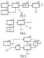
- FIG. 5 shows a preferred embodiment of a high-frequency oscillator for an arrangement according to the invention.
- a coil system 10 is shown, which is part of an arrangement which is used to determine a Nuclear magnetization distribution in part of a body 20.
- the part has a thickness ⁇ z, for example, and lies in the xy plane of the coordinate system (x, y, z) shown.
- the y-axis of the system runs perpendicular to the plane of the drawing.
- the coil system 10 contains some main coils 1 for generating the stationary, uniform main magnetic rock Bo with a strength between 0.2 and 2 Tesla.
- the main coils 1 can, for example, be arranged on the surface of a sphere 2, the center of which lies at the origin 0 of the Cartesian coordinate system (x, y, z) shown, the axes of the main coils 1 coinciding with the z axis.
- the coil system 10 contains, for example, four coils 3 a , 3 b arranged on the same spherical surface, with which the gradient magnetic field G z is generated.
- a first set 3a is excited in the opposite sense with respect to the flow of the second set 3b with a current which is indicated by Figur and ⁇ in the figure.
- ⁇ denotes a current flowing into the cross section of the coil 3 and ⁇ a current flowing out of the cross section of the coil.
- the coil system 10 contains, for example, four rectangular coils 5 (only two of which are shown) or four other coils, such as "Golay coils" for generating the gradient magnetic field G y .
- four coils 7 with the same shape as the coils 5 are used, which are rotated by an angle of 90 ° about the z-axis with respect to the coils 5.
- 1 also shows a coil 11 with which a high-frequency electromagnetic field can be generated and detected.
- FIG. 2 shows an arrangement 15 for carrying out a method according to the invention.
- the Arrangement 15 contains coils 1, 3, 5, 7 and 11, which have already been described with reference to FIG. 1, current transmitters 17, 19, 21 and 23 for exciting coils 1, 3, 5 and 7 and a high-frequency signal transmitter 25 for Excitation of the coil 11.
- the arrangement 15 further contains a high-frequency signal detector 27, a demodulator 28, a sampling circuit 29, processing means such as an analog / digital converter 31, a memory 33 and a computer 35 for performing a signal transformation (for example a Fourier Transformation), a control unit 37 for controlling the sampling times and further a display arrangement 43 and central control means 45, the functions and interrelations of which are explained in more detail below.
- a signal transformation for example a Fourier Transformation
- a method for determining the nuclear magnetization distribution in a body 20 is carried out as described above.
- the process consists of several steps.
- the nuclear spins present in the body are stimulated to resonate.
- the resonance excitation of the nuclear spins takes place by switching on the current generator 17 from the central control unit 45, whereby the coil 1 is excited.
- This creates a stationary and homogeneous magnetic field Bo.
- the high-frequency transmitter 25 is switched on for a short time, so that the coil 11 generates a high-frequency electromagnetic field (HF field).
- the magnetic spins in the body 20 can be excited by the magnetic fields applied, the excited nuclear magnetization forming a certain angle, for example 90 ° (90 ° HF pulse), with the homogeneous magnetic field Bo.
- scanning signals are collected, depending on the type of measurement (for example nuclear spin density distribution, current speed distribution, location-dependent spectroscopy), the gradient fields that are generated by the transmitters 19 and 21, 23 under the control of the central control means 45 may be used.
- the detection of the resonance signal (designated FID signal) is carried out by switching on the high-frequency detector 27, the demodulator 28, the sampling circuit 29, the analog / digital converter 31 and the control unit 37.
- This FID signal is caused by the fact that the RF excitation pulse precess the nuclear magnetization around the field direction of the magnetic field Bo. This nuclear magnetization introduces an induction voltage into the detector coil, the amplitude of which is a measure of the nuclear magnetization.
- the analog sampled FID signals originating from the sampling circuit 29 are converted into digital signals (converter 31) and thus written into a memory 33.
- the central control means 45 stop the transmitters 19, 21 and 23, the sampling circuit 29, the control unit 37 and the analog / digital converter 31.
- the sampled FID signals are stored in the memory 33 and are converted into a Fourier transform implemented an image of the generated nuclear magnetization distribution in that part of the body in which the nuclear spins are excited in a suitable manner.
- the main field Bo has a strength of 2 T and a homogeneity of 25 ppm (parts per million), this results in a gradient magnetic field strength of 5 mT / m and a limitation of the geometric distortion to 1 cm.
- a 1 cm thick RF pulse with a bandwidth of 2 kHz is required for the given gradient magnetic field strength.
- thicker slices must be excited.
- An RF pulse with a bandwidth of 20 kHz is required for a 10 cm thick slice. According to the state of the art, this would require a high-frequency transmitter that would have to deliver a hundred times the peak power.
- the oscillator 25 contains a constant frequency oscillator 61, a low frequency oscillator 63, an amplitude modulator 65, a frequency filter 67 and a further amplitude modulator 69.
- the signal with the frequency f o generated by the oscillator 61 is combined with the signal f generated by the oscillator 63, the frequency ( preferably linear) increases from f1 to f2, fed to the modulator 65.
- the modulator 65 generates an output signal which contains signals with the sum frequency f o + f (upper band) and with the difference frequency f o - f (lower band).
- the filter 67 therefore passes either the frequencies above f o or the frequencies below f o .
- the output signal of the filter 67 reaches the high-frequency coil 11 (FIGS. 1 and 2) via an amplitude modulator 69 (for example a controllable amplifier).
- the change in frequency from f1 to f2 determines the bandwidth of the RF signal generated.
- the modulator 65 (which can also be a four-quadrant multiplier, for example) generates an RF signal with a constant amplitude, which is generated by the modulator 69 with the time signal s (t) (the order envelope of the RF pulse) is multiplied. This time signal is through determines, where s1 (t), s2 (t) are the real or imaginary signals of the Fourier transform of the function selected in the frequency spectrum. Of course, the time signal s (t) change synchronously with the frequency change (oscillator 63).
- the high-frequency oscillator 25 contains a voltage-controlled oscillator 71, which is controlled by a voltage function generator 73. If the frequency generated by the oscillator 71 is linearly dependent on the control voltage, the function generator 73 generates a triangular voltage, which of course is associated with the time signal s (t) must be synchronized with which an amplitude modulator 75 is controlled to form the required RF pulse. The output of the amplitude modulator 75 is connected to the high-frequency coil 11.
- This angle if it is not equal to zero, causes an additional phase shift in the phase of the nuclear spins with twice the size of this angle.
- the dephasing of a 180 ° pulse is therefore determined by the following: The same reasoning can of course be applied to the frequency shift due to (main) field inhomogeneities.
- the relationship must be linearly frequency-modulated high-frequency pulses to receive a so-called stimulated echo signal be fulfilled if the undesired phase shifts between nuclear spins at different locations in the examination area are to be avoided.
- g1, g2, g3 are the gradients of the magnetic gradient fields during the first, the second and the third high-frequency pulse and ⁇ 1, ⁇ 2, ⁇ 3 the frequency change in the first, second and third high-frequency pulse related to the time unit.
- the compensation can be achieved in different ways. For example, it results when the frequency change of the second and third pulses is twice as large as the frequency change of the first pulse. Another possibility provides that the gradient of the magnetic gradient field during the first high-frequency pulse is larger by a factor of ⁇ 2 than the gradient for both the second and the third high-frequency pulse.
- the desired compensation of the phase shift is obtained if at least the gradients g2 and g3 during the second and third high-frequency pulse are equal to one another and the frequency changes per unit time ⁇ 2 and ⁇ 3 are the same size but opposite signs have, ie when the frequency changes at the same speed during the pulses, but increases with one pulse and decreases with the other.
- the desired compensation of the phase shifts results if both the gradients g1, g2 and the frequency changes per unit time ⁇ 1 and ⁇ 2 are the same size.
Claims (12)
- Procédé pour déterminer une distribution de la magnétisation nucléaire dans une région d'un corps, selon lequel on produit un champ magnétique homogène constant, dans lequel se trouve la région du corps et selon lequela) on produit des impulsions électromagnétiques de haute fréquence en vue d'engendrer un signal de résonance magnétique nucléaire,b) après une période de préparation, pendant un temps de mesure, on prélève, par échantillonnage, un groupe d'échantillons de signal du signal de résonance,c) après une période d'attente, on répète toujours quelques fois les opérations a) et b) pour obtenir plusieurs (n') groupes comprenant chacun (n) échantillons de signal, à partir desquels, après une transformation de signal, on établit une image de la distribution de la magnétisation nucléaire produite,les impulsions électromagnétiques de haute fréquence étant des impulsions modulées en fréquence, caractérisé en ce que la variation de la fréquence des impulsions haute fréquence par rapport à l'unité de temps est choisie telle que les déphasages des spins nucléaires provoqués par les impulsions haute fréquence individuelles se compensent mutuellement et que, dans le cas où un champ magnétique de gradient est appliqué à chaque impulsion haute fréquence, les déphasages provoqués par les impulsions haute fréquence individuelles de spins nucléaires exposés à des champs magnétiques de gradients différents se compensent mutuellement.
- Procédé suivant la revendication 1, selon lequel le signal de résonance magnétique nucléaire est enregistré après au moins deux impulsions haute fréquence, pendant lesquelles un champ magnétique de gradient est chaque fois actif, caractérisé en ce que l'intensité de champ des champs de gradients actifs pendant les impulsions haute fréquence et/ou la variation de la fréquence des impulsions haute fréquence par unité de temps sont choisies telles que les déphasages des spins nucléaires provoqués par les impulsions individuelles se compensent mutuellement.
- Procédé suivant la revendication 1 pour enregistrer des signaux d'écho de spin, caractérisé en ce que, pendant une impulsion à 90°, un champ magnétique de gradient est enclenché et pendant une impulsion à 180°, un champ magnétique de gradient s'étendant dans le même sens est actif, et que les champs de gradients ou les variations de fréquence par unité de temps sont choisis de telle façon que la relation

- Procédé suivant la revendication 2, caractérisé en ce que, pour l'enregistrement de signaux d'écho stimulés à l'aide de deux impulsions à 90° successives et d'au moins une troisième impulsion pendant lesquelles des champs de gradients s'étendant dans le même sens sont chaque fois présents, les champs de gradients et la modulation de fréquence des impulsions sont choisis tels que la relation

- Procédé suivant la revendication 3, caractérisé en ce que la variation de fréquence par unité de temps de l'impulsion haute fréquence à 180° correspond approximativement au double de la variation de la fréquence pour l'impulsion à 90°, ces deux impulsions présentant à peu près la même excursion de fréquence.
- Procédé suivant la revendication 5, caractérisé en ce que l'amplitude de l'impulsion à 180° correspond au moins au double de l'amplitude de l'impulsion à 90°.
- Procédé suivant la revendication 5, caractérisé en ce que le champ magnétique de gradient présent pendant l'impulsion à 90° a une intensité qui est supérieure du facteur √
2 à l'intensité du champ magnétique de gradient présent pendant l'impulsion à 180°. - Procédé suivant la revendication 1, caractérisé en ce qu'après la production d'un premier signal d'écho de spins nucléaires, au moins un autre signal d'écho de spins nucléaires est produit à l'aide d'au moins une impulsion haute fréquence à 180° composée et que l'impulsion haute fréquence à 180° composée est composée d'un nombre impair d'impulsions à 180°, dont la somme des contributions quadratiques au déphasage des spins nucléaires est égale à zéro.
- Procédé suivant la revendication 8, caractérisé en ce que l'impulsion à 180° composée est composée de trois impulsions à 180°, la variation de fréquence par unité de temps de la première et de la troisième impulsion à 180° correspondant au double de la variation de fréquence par unité de temps de la deuxième impulsion à 180° et les trois impulsions à 180° présentant chaque fois la même excursion de fréquence.
- Procédé suivant la revendication 9, caractérisé en ce que l'amplitude de la deuxième impulsion à 180° correspond à la moitié de l'amplitude de la première et de la troisième impulsion à 180°.
- Procédé suivant l'une quelconque des revendications 1 à 10, caractérisé en ce que le spectre de fréquences de l'impulsion haute fréquence est approximativement de forme rectangulaire à flancs antérieurs et postérieurs qui sont déterminés par une courbe de Gauss.
- Appareil à résonance magnétique nucléaire pour l'exécution du procédé suivant la revendication 1, qui comprend les moyens suivants :a) un moyen pour produire un champ magnétique homogène constant,b) un oscillateur haute fréquence et une bobine haute fréquence pour produire un rayonnement haute fréquence électromagnétique modulé en fréquence, la fréquence produite étant fonction du temps,c) un moyen pour produire un champ magnétique de gradient,d) un moyen d'échantillonnage pour échantillonner un signal de résonance produit par les moyens cités sous a) et b),e) un moyen de traitement pour traiter les groupes d'échantillons de signal fournis par le moyen d'échantillonnage de manière à établir une image d'une distribution de la magnétisation nucléaire, etf) un moyen de commande pour commander les moyens cités sous b) à e) pour engendrer, conditionner, échantillonner et traiter les groupes d'échantillons de signal, caractérisé par des moyens programmés pour régler la variation par unité de temps de la fréquence des impulsions haute fréquence successives et/ou l'intensité du champ magnétique de gradient éventuellement présent pendant les impulsions haute fréquence en vue de la compensation des déphasages des spins nucléaires provoqués par les impulsions haute fréquence individuelles.
Applications Claiming Priority (4)
| Application Number | Priority Date | Filing Date | Title |
|---|---|---|---|
| NL8401382A NL8401382A (nl) | 1984-05-02 | 1984-05-02 | Werkwijze en inrichting voor het bepalen van een kernmagnetisatieverdeling in een deel van een lichaam. |
| NL8401382 | 1984-05-02 | ||
| NL8402855A NL8402855A (nl) | 1984-09-18 | 1984-09-18 | Werkwijze en inrichting voor het bepalen van een kernmagnetisatieverdeling in een deel van een lichaam. |
| NL8402855 | 1984-09-18 |
Publications (2)
| Publication Number | Publication Date |
|---|---|
| EP0164142A1 EP0164142A1 (fr) | 1985-12-11 |
| EP0164142B1 true EP0164142B1 (fr) | 1991-03-27 |
Family
ID=26645947
Family Applications (1)
| Application Number | Title | Priority Date | Filing Date |
|---|---|---|---|
| EP85200644A Expired - Lifetime EP0164142B1 (fr) | 1984-05-02 | 1985-04-24 | Procédé et dispositif pour déterminer la distribution de la magnétisation nucléaire dans une région d'un corps |
Country Status (5)
| Country | Link |
|---|---|
| US (1) | US4707659A (fr) |
| EP (1) | EP0164142B1 (fr) |
| CA (1) | CA1253917A (fr) |
| DE (1) | DE3582275D1 (fr) |
| IL (2) | IL75039A0 (fr) |
Families Citing this family (10)
| Publication number | Priority date | Publication date | Assignee | Title |
|---|---|---|---|---|
| DE3524682A1 (de) * | 1985-07-11 | 1987-01-15 | Philips Patentverwaltung | Kernspinuntersuchungsverfahren |
| US4689566A (en) * | 1985-07-17 | 1987-08-25 | Advanced Nmr Systems, Inc. | NMR phase encoding using phase varying rf pulses |
| US4703267A (en) * | 1985-07-17 | 1987-10-27 | Advanced Nmr Systems, Inc. | High dynamic range in NMR data acquisition |
| NL8601002A (nl) * | 1986-04-21 | 1987-11-16 | Philips Nv | Werkwijze en inrichting voor het bepalen van een kernmagnetisatieverdeling in deel van een lichaam. |
| JPS63109847A (ja) * | 1986-10-29 | 1988-05-14 | 株式会社日立メデイコ | 核磁気共鳴映像装置 |
| US5307014A (en) * | 1991-10-18 | 1994-04-26 | Siemens Medical Systems, Inc. | Inflow MR angiography with spatially variable flip angles |
| US5258711A (en) * | 1992-04-20 | 1993-11-02 | General Electric Company | NMR selective excitation of bent slices |
| CA2108103C (fr) * | 1993-10-08 | 2001-02-13 | Michel T. Fattouche | Methode et appareil de compression, de traitement et de decomposition spectrale de signaux electromagnetiques et acoustiques |
| US7514923B2 (en) * | 2005-11-07 | 2009-04-07 | General Electric Company | Method for localized excitation for accurate center frequency measurements with MRI |
| EP4020013A4 (fr) * | 2019-08-23 | 2023-08-23 | Spacety Co., Ltd (Changsha) | Système de détection à distance basé sur la formation de satellites, et système de constellation |
Citations (1)
| Publication number | Priority date | Publication date | Assignee | Title |
|---|---|---|---|---|
| US3975675A (en) * | 1974-02-05 | 1976-08-17 | Compagnie D'applications Mecaniques A L'electronique Au Cinema Et A L'atomistique (C.A.M.E.C.A.) | Impulse response magnetic resonance spectrometer |
Family Cites Families (13)
| Publication number | Priority date | Publication date | Assignee | Title |
|---|---|---|---|---|
| US4021726A (en) * | 1974-09-11 | 1977-05-03 | National Research Development Corporation | Image formation using nuclear magnetic resonance |
| CA1052861A (fr) * | 1975-03-18 | 1979-04-17 | Varian Associates | Zeugmatographie par resonance gyromagnetique a l'aide de la transformee de fourier |
| GB2037999B (en) * | 1978-12-13 | 1983-01-06 | Emi Ltd | Imaging systems |
| US4319190A (en) * | 1980-03-06 | 1982-03-09 | Bell Telephone Laboratories, Incorporated | Nuclear magnetic resonance imaging in space and frequency coordinates |
| US4451788A (en) * | 1980-03-14 | 1984-05-29 | National Research Development Corporation | Methods of producing image information from objects |
| DE3124435A1 (de) * | 1981-06-22 | 1983-01-20 | Siemens AG, 1000 Berlin und 8000 München | Geraet zur erzeugung von bildern eines untersuchungsobjektes |
| US4521749A (en) * | 1981-10-01 | 1985-06-04 | National Research Development Corporation | Simultaneous amplitude and angle modulation using detection of complex zeroes |
| US4486708A (en) * | 1981-12-21 | 1984-12-04 | Albert Macovski | Selective material projection imaging system using nuclear magnetic resonance |
| DE3209263A1 (de) * | 1982-03-13 | 1983-09-22 | Bruker Medizintechnik Gmbh, 7512 Rheinstetten | Verfahren zum messen der magnetischen kernresonanz |
| US4431968A (en) * | 1982-04-05 | 1984-02-14 | General Electric Company | Method of three-dimensional NMR imaging using selective excitation |
| NL8203519A (nl) * | 1982-09-10 | 1984-04-02 | Philips Nv | Werkwijze en inrichting voor het bepalen van een kernmagnetisatieverdeling in een deel van een lichaam. |
| US4480228A (en) * | 1982-10-15 | 1984-10-30 | General Electric Company | Selective volume method for performing localized NMR spectroscopy |
| US4540958A (en) * | 1983-09-30 | 1985-09-10 | International Telephone And Telegraph Corporation | Zero if frequency-modulator |
-
1985
- 1985-04-24 DE DE8585200644T patent/DE3582275D1/de not_active Expired - Lifetime
- 1985-04-24 EP EP85200644A patent/EP0164142B1/fr not_active Expired - Lifetime
- 1985-04-29 IL IL75039A patent/IL75039A0/xx unknown
- 1985-04-30 US US06/729,007 patent/US4707659A/en not_active Expired - Fee Related
- 1985-05-02 CA CA000480631A patent/CA1253917A/fr not_active Expired
-
1989
- 1989-04-29 IL IL75039A patent/IL75039A/xx unknown
Patent Citations (1)
| Publication number | Priority date | Publication date | Assignee | Title |
|---|---|---|---|---|
| US3975675A (en) * | 1974-02-05 | 1976-08-17 | Compagnie D'applications Mecaniques A L'electronique Au Cinema Et A L'atomistique (C.A.M.E.C.A.) | Impulse response magnetic resonance spectrometer |
Also Published As
| Publication number | Publication date |
|---|---|
| DE3582275D1 (de) | 1991-05-02 |
| CA1253917A (fr) | 1989-05-09 |
| IL75039A (en) | 1990-02-09 |
| EP0164142A1 (fr) | 1985-12-11 |
| IL75039A0 (en) | 1985-08-30 |
| US4707659A (en) | 1987-11-17 |
Similar Documents
| Publication | Publication Date | Title |
|---|---|---|
| DE2921253C2 (fr) | ||
| EP0074022B1 (fr) | Dispositif de tomographie à spin nucléaire | |
| DE2822953C2 (fr) | ||
| DE2921252A1 (de) | Kernmagnetische resonanz-vorrichtung zur untersuchung einer scheibe eines koerpers | |
| DE2928551A1 (de) | Verfahren und vorrichtung zum aufzeichnen von linien der atomkerndichte innerhalb eines objekts unter anwendung der magnetischen kernresonanz | |
| DE3437509C2 (fr) | ||
| DE4227162C2 (de) | Iterative Shim-Verfahren für einen Grundfeldmagneten eines Kernspintomographiegerätes | |
| EP0089534A1 (fr) | Procédé de mesure de la résonance magnétique nucléaire | |
| EP0164142B1 (fr) | Procédé et dispositif pour déterminer la distribution de la magnétisation nucléaire dans une région d'un corps | |
| DE2328472B2 (de) | Verfahren zur magnetischen Resonanzspektroskopie und dafür geeignetes Impulsspektrometer | |
| DE4224237A1 (de) | Verfahren und vorrichtung zur selektiven anregung der kernspins bei abbildungen mittels magnetischer kernresonanz | |
| EP0412602B1 (fr) | Procédé de spectroscopie RMN et dispositif pour sa mise en oeuvre | |
| EP0242911A1 (fr) | Procédé et dispositif pour déterminer la distribution de la magnétisation nucléaire dans une région d'un corps | |
| DE3539256C2 (de) | Verfahren zur Darstellung der kernmagnetischen Eigenschaften eines zu untersuchenden Objektes | |
| EP0322006A2 (fr) | Procédé de spectroscopie par résonance magnétique nucléaire | |
| EP0205199A1 (fr) | Procédé pour réduire les artefacts dans la formation d'images par tomographie de spin nucléaire | |
| EP1107015B1 (fr) | Procédé de la résonance magnétique pour la génération d'impulsions navigatrices | |
| EP0261743B1 (fr) | Procédé pour déterminer la distribution spectrale de la magnétisation nucléaire dans un volume limité | |
| EP0233675B1 (fr) | Procédé pour déterminer la distribution spectrale de la magnétisation nucléaire dans un volume limité et dispositif pour la mise en oeuvre du procédé | |
| WO1990010878A1 (fr) | Procede de spectroscopie ou de tomographie par resonance magnetique dans une zone preselectionnee d'un materiau et application de ce procede | |
| EP0232945A2 (fr) | Procédé pour déterminer la distribution de la magnétisation nucléaire dans une couche de région d'examen et tomographe à spin nucléaire pour la mise en oeuvre du procédé | |
| EP0496447A1 (fr) | Procédé de spectroscopie RMN et dispositif de mise en oeuvre du procédé | |
| EP0212734B1 (fr) | Procédé pour déterminer un spectre de résonance magnétique nucléaire | |
| DE4232883C2 (de) | Adiabatischer Hochfrequenzpuls für die Anregung von Kernspins | |
| EP0478030A1 (fr) | Procédé pour la spectroscopie RMN à deux dimensions |
Legal Events
| Date | Code | Title | Description |
|---|---|---|---|
| PUAI | Public reference made under article 153(3) epc to a published international application that has entered the european phase |
Free format text: ORIGINAL CODE: 0009012 |
|
| AK | Designated contracting states |
Designated state(s): BE DE FR GB IT NL SE |
|
| 17P | Request for examination filed |
Effective date: 19860530 |
|
| 17Q | First examination report despatched |
Effective date: 19870928 |
|
| GRAA | (expected) grant |
Free format text: ORIGINAL CODE: 0009210 |
|
| AK | Designated contracting states |
Kind code of ref document: B1 Designated state(s): BE DE FR GB IT NL SE |
|
| PG25 | Lapsed in a contracting state [announced via postgrant information from national office to epo] |
Ref country code: SE Effective date: 19910327 Ref country code: NL Effective date: 19910327 Ref country code: IT Free format text: LAPSE BECAUSE OF FAILURE TO SUBMIT A TRANSLATION OF THE DESCRIPTION OR TO PAY THE FEE WITHIN THE PRESCRIBED TIME-LIMIT;WARNING: LAPSES OF ITALIAN PATENTS WITH EFFECTIVE DATE BEFORE 2007 MAY HAVE OCCURRED AT ANY TIME BEFORE 2007. THE CORRECT EFFECTIVE DATE MAY BE DIFFERENT FROM THE ONE RECORDED. Effective date: 19910327 Ref country code: GB Effective date: 19910327 Ref country code: FR Effective date: 19910327 Ref country code: BE Effective date: 19910327 |
|
| REF | Corresponds to: |
Ref document number: 3582275 Country of ref document: DE Date of ref document: 19910502 |
|
| EN | Fr: translation not filed | ||
| NLV1 | Nl: lapsed or annulled due to failure to fulfill the requirements of art. 29p and 29m of the patents act | ||
| GBV | Gb: ep patent (uk) treated as always having been void in accordance with gb section 77(7)/1977 [no translation filed] | ||
| PLBE | No opposition filed within time limit |
Free format text: ORIGINAL CODE: 0009261 |
|
| STAA | Information on the status of an ep patent application or granted ep patent |
Free format text: STATUS: NO OPPOSITION FILED WITHIN TIME LIMIT |
|
| PG25 | Lapsed in a contracting state [announced via postgrant information from national office to epo] |
Ref country code: DE Effective date: 19920201 |
|
| 26N | No opposition filed |