EP0164125A2 - Fuel injection control method for internal combustion engines - Google Patents
Fuel injection control method for internal combustion engines Download PDFInfo
- Publication number
- EP0164125A2 EP0164125A2 EP85107023A EP85107023A EP0164125A2 EP 0164125 A2 EP0164125 A2 EP 0164125A2 EP 85107023 A EP85107023 A EP 85107023A EP 85107023 A EP85107023 A EP 85107023A EP 0164125 A2 EP0164125 A2 EP 0164125A2
- Authority
- EP
- European Patent Office
- Prior art keywords
- fuel
- acceleration
- valve opening
- internal combustion
- opening pulse
- Prior art date
- Legal status (The legal status is an assumption and is not a legal conclusion. Google has not performed a legal analysis and makes no representation as to the accuracy of the status listed.)
- Granted
Links
Images


Classifications
-
- F—MECHANICAL ENGINEERING; LIGHTING; HEATING; WEAPONS; BLASTING
- F02—COMBUSTION ENGINES; HOT-GAS OR COMBUSTION-PRODUCT ENGINE PLANTS
- F02D—CONTROLLING COMBUSTION ENGINES
- F02D41/00—Electrical control of supply of combustible mixture or its constituents
- F02D41/02—Circuit arrangements for generating control signals
- F02D41/18—Circuit arrangements for generating control signals by measuring intake air flow
- F02D41/187—Circuit arrangements for generating control signals by measuring intake air flow using a hot wire flow sensor
-
- F—MECHANICAL ENGINEERING; LIGHTING; HEATING; WEAPONS; BLASTING
- F02—COMBUSTION ENGINES; HOT-GAS OR COMBUSTION-PRODUCT ENGINE PLANTS
- F02D—CONTROLLING COMBUSTION ENGINES
- F02D41/00—Electrical control of supply of combustible mixture or its constituents
- F02D41/02—Circuit arrangements for generating control signals
- F02D41/04—Introducing corrections for particular operating conditions
- F02D41/10—Introducing corrections for particular operating conditions for acceleration
- F02D41/105—Introducing corrections for particular operating conditions for acceleration using asynchronous injection
-
- F—MECHANICAL ENGINEERING; LIGHTING; HEATING; WEAPONS; BLASTING
- F02—COMBUSTION ENGINES; HOT-GAS OR COMBUSTION-PRODUCT ENGINE PLANTS
- F02D—CONTROLLING COMBUSTION ENGINES
- F02D41/00—Electrical control of supply of combustible mixture or its constituents
- F02D41/02—Circuit arrangements for generating control signals
- F02D41/18—Circuit arrangements for generating control signals by measuring intake air flow
-
- F—MECHANICAL ENGINEERING; LIGHTING; HEATING; WEAPONS; BLASTING
- F02—COMBUSTION ENGINES; HOT-GAS OR COMBUSTION-PRODUCT ENGINE PLANTS
- F02B—INTERNAL-COMBUSTION PISTON ENGINES; COMBUSTION ENGINES IN GENERAL
- F02B75/00—Other engines
- F02B75/02—Engines characterised by their cycles, e.g. six-stroke
- F02B2075/022—Engines characterised by their cycles, e.g. six-stroke having less than six strokes per cycle
- F02B2075/027—Engines characterised by their cycles, e.g. six-stroke having less than six strokes per cycle four
Definitions
- the present invention relates to a fuel injection controlling method for an internal combustion engine, and more particularly to a fuel injection controlling method for an internal combustion engine for automobiles using a hot wire air flow meter wherein the rate of fuel injection ⁇ can be adjusted during acceleration.
- valve opening pulse generating means for the fuel increment independently of the basic valve opening pulse for causing the injectors to inject fuel normally during the normal condition, and the valve opening pulse for the fuel increment is determined the duration dependent on the water temperature of the internal combustion engine.
- the above electronic fuel injector employs a vane air flow meter. Therefore, it can not abruptly increase the rate of air intake into an engine during acceleration. From this reason, a relatively rich mixture is supplied at the beginning of acceleration.
- a hot wire air flow meter employed in the air flow meter requires fine adjustment during acceleration, because it includes no member interrupting air intake as seen in the vane type air flow meter; hence, it causes an instantaneous flow of air into the engine.
- the hot wire air flow meter which detects the volume of air is advantageous in that it allows air to be supplied to the engine more rapidly during acceleration because it has no throttle component. It does, however, have the problem of delayed fuel feed, that is, a lag in response time. This delay in fuel feed response time requires fine adjustment based on acceleration and other parameters.
- An object of the present invention is to provide a fuel injection controlling method for an internal combustion engine wherein optimal acceleration characteristics can be obtained.
- Another object of the present invention is to provide a fuel injection controlling method for an internal combustion engine wherein fuel increment depending on the state of a running engine excepting the water temperature can be adjusted.
- Another object of the present invention is to provide a fuel injection controlling method for an internal com- bustion engine wherein delayed fuel feed can be adjusted.
- Another object of the present invention is to provide a fuel injection controlling method for an internal combustion engine wherein acceleration matching between the state after deceleration and the state after normal becomes possible.
- Another object of the present invention is to provide a fuel injection controlling method for an internal combustion engine wherein speed up revolution time of acceleration from idling to the fully open state under no load can be shortened.
- Another object of the present invention is to provide a fuel injection controlling method for an internal combustion engine wherein inadequate acceleration during rapid acceleration uhich is to be effected after fuel reduction for deceleration can be improved.
- the present invention is to provide a fuel injection control method for internal combustion engines including the steps of: controlling the opening time of fuel injector in accordance with the control content previously programmed based on various operational parameters including air intake volume, the number of revolutions and temperature of the engine; measuring the air intake volume by a hot wire air flow meter; generating a signal of an idle switch for detecting a closed state of a throttle valve adapted to control the intake air amount; and generating a valve opening pulse for fuel increment independent of a basic valve opening pulse which causes the injector to inject fuel normally during the normal condition; and is characterized in that the duration of the valve opening pulse for a fuel increment is controlled dependent on at least one of selected from variations in the air intake volume per unit time, a closing signal for the throttle valve, a signal indicating the number of revolutions of the internal combustion engine, etc., and independent of the duration of the basic valve opening pulse.
- FIG. 1 shows an engine system to which the present invention is applied.
- An engine 1 has intake pipes 2 which are provided with the fuel injection valves (injectors) 3 corresponding to the number of cylinders. These intake pipes 2 are brought into a single pipe at a collector 4 in the upstream side, and have a throttle valve 5 for determining the amount of intake for the engine further upstream.
- a control unit CU 12 also receives a signal 11 from engine temperature, an exhaust gas signal from an oxygen concentration measuring sensor 10, and a signal from an idle switch li, etc.
- Fuel is supplied to the engine 1 by opening a valve on each of the fuel injector 3, and the amount of fuel is measured based on valve opening time. Fuel is pressurized and regulated by a fuel pump 8 and a regulator 9.
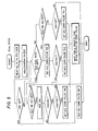
- Fig. 2 is a block diagram showing the relationship between input and output depicted in Fig. 1.
- the left side includes sensors and the right side includes actuators.
- wave shaping circuits and AD converters are arranged on the left side, an I/O LSI section for implementing therein exchange of input/output and arithmetic processing and a CPU for giving instructions to the I/O LSI section are at the center, and a circuit for driving the output actuators on the right side.
- injection timing for example in a 4-cylinder, 4-cycle engine, will be described with reference to Fig. 3.
- fuel is usually injected once per revolution, i.e., at the timing of A and C, for all four cylinders.
- the sections A and C are respectively the basic valve opening pulses for causing the injector to inject fuel normally during the normal condition.
- a fuel increment pulse (interrupt pulse) described in the present invention is a pulse shown in the section of B which is generated immediately upon detection of acceleration, so as to inject fuel at that time.
- acceleration may be detected based on, for example, an ON ⁇ OFF signal of the idle switch 14 or a closing signal of the idle switch 14 indicating that a throttle valve 5 has been opened from an idle state, and the rate of variation (AQa) of the air intake volume Qa per unit time.
- the magnitude of acceleration can be detected based on the value (AQa/Qa) of the rate of variation of the air intake volume Qa during a predetermined time ( ⁇ t).
- Table 1 shows an example of setting the fuel increment pulse (interrupt pulse) to a running vehicle in response to the magnitude of acceleration.
- the process after acceleration is divided depending on the condition before acceleration. More specifically, after reducing fuel feed during deceleration, a large amount of fuel must be supplied to compensate for drying-up in the intake system during fuel reduction. Also after the normal condition, adjusting acceleration requires changes to correspond to the fully closed state of the throttle valve and other states thereof.
- acceleration is detected as a combination of the rate of variation (AQa) in the air intake volume per unit time and the idle switch setting.
- AQa rate of variation
- idle switch setting the "after idling" indicates an interrupt pulse based on detection of acceleration using the idle switch.
- the reason for detecting acceleration based on both the idle switch and the rate of variation (AQa) in the air intake volume per unit time is in that detection with the idle switch always occurs earlier than detection with the rate of variation (AQa) in the air intake volume per unit time.
- this is attributable to a delay in the intake system accompanying detection of the rate of variation (AQa) in the air intake volume per unit time. Though this delay is relatively short, it is still longer than that accompanying the opening of the throttle valve.
- the process is divided into slow acceleration (under light load. 5% ⁇ A Q a ⁇ 37.5%) and rapid acceleration ( ⁇ Qa ⁇ 37.5%).
- slow acceleration an interrupt pulse of 3 ms is generated; for rapid acceleration, interrupt pulses of 9 ms are generated, (one for each detected acceleration rate).
- the magnitudes of the above interrupt pulses are set preferably to have about 1.5-5 ms duration for slow acceleration and to have about 6-12 ms duration for rapid acceleration, respectively.
- An interrupt pulse based on the idle switch is set to , have, by way of example, a relatively long duration of 9 ms.
- the magnitude of the above interrupt pulse by the after idling is set preferably to have about 6-12 ms duration.
- An interrupt pulse based on the rate of variation (AQa) in the air take volume per unit time in normal condition is set to have a 3 ms duration for slow acceleration (5% ⁇ AQa ⁇ 10%) and is set to have a 6 ms duration for rapid acceleration ( ⁇ Qa ⁇ 10%) respectively, and the fuel is injected.
- the magnitutes of the above interrupt pulses are set preferably to have about 1.5-5 ms duration for slow acceleration and to have above 4-8 ms duration for rapid acceleration, respectively.
- an interrupt pulse based on the idle switch may be set to a shorter duration, e.g., 3 ms, than that during deceleration.
- the magnitude of the above interrupt pulse is set preferably to have 1.5-5 ms duration.
- Fig. 4 shows the experimental results obtained from application of the above-mentioned adjustment.
- the graph of Fig. 4 represents an example of rapid acceleration from idling to the fully open state under no load. It is evident from Fig. 4 that, as a result of adjusting with the additional interrupt pulses during acceleration, revolution time is speeded up from To of about 200 ms in the prior art to T of about 120 ms in the present invention.
- Fig. 5 shows a flow chart sheet for realizing the adjustment described in connection with Table 1.
- an interrupt pulse TA2 (3 ms) due to the condition after idling is set and thereafter an interrupt pulse TA3, also herein inherently divided into two types.
- -interrupt pulses TA3', 3 ms in Table 1, and TA3", 6 ms in Table 1 - is set based on ⁇ Qa.
- the left-hand loop represents acceleration from the decelerated state.
- an interrupt pulse TA4 (9 ms) is issued due to the state after idling and acceleration is then determined on the basis of AQa. If A5 > AQa > A6, an interrupt pulse TA6 (3 ms) is issued and adjustment is completed therewith.
- the present invention is to overcome this problem. Namely, when AQa > A5, an interrupt pulse TA5 is set.
Abstract
Description
- The present invention relates to a fuel injection controlling method for an internal combustion engine, and more particularly to a fuel injection controlling method for an internal combustion engine for automobiles using a hot wire air flow meter wherein the rate of fuel injection ¡ can be adjusted during acceleration.
- Conventional acceleration adjustment in fuel injection devices of the internal combustion engine for automobiles has been provided the valve opening pulse generating means for the fuel increment independently of the basic valve opening pulse for causing the injectors to inject fuel normally during the normal condition, and the valve opening pulse for the fuel increment is determined the duration dependent on the water temperature of the internal combustion engine. (Japanese Patent Laid Open Publication No. 5841/ 1984).
- However, the above acceleration adjustment in fuel injection devices has not provided fine adjustment of the fuel increment pulse depending on the state of a running engine excepting the water temperature.
- The above electronic fuel injector (MPI system) employs a vane air flow meter. Therefore, it can not abruptly increase the rate of air intake into an engine during acceleration. From this reason, a relatively rich mixture is supplied at the beginning of acceleration.
- However, because an inherent delay exists in air intake into the engine, it has been impossible to achieve abrupt acceleration. On the rapid acceleration from idling to the fully open state under no load, the speeded up revolution time (To) is about 200 ms (confer Fig. 4). i
- Besides, a hot wire air flow meter employed in the air flow meter requires fine adjustment during acceleration, because it includes no member interrupting air intake as seen in the vane type air flow meter; hence, it causes an instantaneous flow of air into the engine.
- The hot wire air flow meter which detects the volume of air is advantageous in that it allows air to be supplied to the engine more rapidly during acceleration because it has no throttle component. It does, however, have the problem of delayed fuel feed, that is, a lag in response time. This delay in fuel feed response time requires fine adjustment based on acceleration and other parameters.
- An object of the present invention is to provide a fuel injection controlling method for an internal combustion engine wherein optimal acceleration characteristics can be obtained.
- Another object of the present invention is to provide a fuel injection controlling method for an internal combustion engine wherein fuel increment depending on the state of a running engine excepting the water temperature can be adjusted.
- Another object of the present invention is to provide a fuel injection controlling method for an internal com- bustion engine wherein delayed fuel feed can be adjusted.
- Another object of the present invention is to provide a fuel injection controlling method for an internal combustion engine wherein acceleration matching between the state after deceleration and the state after normal becomes possible.
- Another object of the present invention is to provide a fuel injection controlling method for an internal combustion engine wherein speed up revolution time of acceleration from idling to the fully open state under no load can be shortened.
- Another object of the present invention is to provide a fuel injection controlling method for an internal combustion engine wherein inadequate acceleration during rapid acceleration uhich is to be effected after fuel reduction for deceleration can be improved.
- The present invention is to provide a fuel injection control method for internal combustion engines including the steps of: controlling the opening time of fuel injector in accordance with the control content previously programmed based on various operational parameters including air intake volume, the number of revolutions and temperature of the engine; measuring the air intake volume by a hot wire air flow meter; generating a signal of an idle switch for detecting a closed state of a throttle valve adapted to control the intake air amount; and generating a valve opening pulse for fuel increment independent of a basic valve opening pulse which causes the injector to inject fuel normally during the normal condition; and is characterized in that the duration of the valve opening pulse for a fuel increment is controlled dependent on at least one of selected from variations in the air intake volume per unit time, a closing signal for the throttle valve, a signal indicating the number of revolutions of the internal combustion engine, etc., and independent of the duration of the basic valve opening pulse.
- It is possible to obtain optimum acceleration by varying the adjustment depending on conditions for interrupt adjustment during acceleration. Further, by applying the judgement of conditions for adjustment after fuel reduction for deceleration, it has become possible to acceleration matching between the state after deceleration and the state after normal operation.
-
- Fig. 1 is an engine system view for embodying the present invention.
- Fig. 2 is a block diagram view showing the relationship between input and output described in Fig. 1.
- Fig. 3 is an explanatory view of engine injection timing.
- Fig. 4 is an explanatory graph of experimental results of speed up revolution times respectively according to both the present invention and the prior art.
- Fig. 5 is an explanatory flow chart sheet for realizing the acceleration adjusting method of the present invention.
- One embodiment of the present invention will be described. Fig. 1 shows an engine system to which the present invention is applied. An
engine 1 hasintake pipes 2 which are provided with the fuel injection valves (injectors) 3 corresponding to the number of cylinders. Theseintake pipes 2 are brought into a single pipe at acollector 4 in the upstream side, and have athrottle valve 5 for determining the amount of intake for the engine further upstream. - Such an amount of intake for the
engine 1 is measured by a hot wireair flow meter 6 provided still further upstream. Engine revolutions are counted by a revolution sensor 13. In addition to the above, acontrol unit CU 12 also receives a signal 11 from engine temperature, an exhaust gas signal from an oxygenconcentration measuring sensor 10, and a signal from an idle switch li, etc. - Fuel is supplied to the
engine 1 by opening a valve on each of thefuel injector 3, and the amount of fuel is measured based on valve opening time. Fuel is pressurized and regulated by a fuel pump 8 and aregulator 9. - Fig. 2 is a block diagram showing the relationship between input and output depicted in Fig. 1. With respect to a control unit CU, the left side includes sensors and the right side includes actuators.
- In the control unit CU, wave shaping circuits and AD converters are arranged on the left side, an I/O LSI section for implementing therein exchange of input/output and arithmetic processing and a CPU for giving instructions to the I/O LSI section are at the center, and a circuit for driving the output actuators on the right side.
- Next, injection timing, for example in a 4-cylinder, 4-cycle engine, will be described with reference to Fig. 3. In the 4-cylinder, 4-cycle engine, fuel is usually injected once per revolution, i.e., at the timing of A and C, for all four cylinders.
- The sections A and C are respectively the basic valve opening pulses for causing the injector to inject fuel normally during the normal condition.
- A fuel increment pulse (interrupt pulse) described in the present invention is a pulse shown in the section of B which is generated immediately upon detection of acceleration, so as to inject fuel at that time.
- In the present invention, acceleration may be detected based on, for example, an ON → OFF signal of the
idle switch 14 or a closing signal of theidle switch 14 indicating that athrottle valve 5 has been opened from an idle state, and the rate of variation (AQa) of the air intake volume Qa per unit time. The magnitude of acceleration can be detected based on the value (AQa/Qa) of the rate of variation of the air intake volume Qa during a predetermined time (Δt). - Table 1 shows an example of setting the fuel increment pulse (interrupt pulse) to a running vehicle in response to the magnitude of acceleration.

- By way of example, the process after acceleration is divided depending on the condition before acceleration. More specifically, after reducing fuel feed during deceleration, a large amount of fuel must be supplied to compensate for drying-up in the intake system during fuel reduction. Also after the normal condition, adjusting acceleration requires changes to correspond to the fully closed state of the throttle valve and other states thereof.
- Further, acceleration is detected as a combination of the rate of variation (AQa) in the air intake volume per unit time and the idle switch setting. In the Table 1, the "after idling" indicates an interrupt pulse based on detection of acceleration using the idle switch.
- The reason for detecting acceleration based on both the idle switch and the rate of variation (AQa) in the air intake volume per unit time is in that detection with the idle switch always occurs earlier than detection with the rate of variation (AQa) in the air intake volume per unit time. Experiments have shown that this is attributable to a delay in the intake system accompanying detection of the rate of variation (AQa) in the air intake volume per unit time. Though this delay is relatively short, it is still longer than that accompanying the opening of the throttle valve.
- Description will now be made by referring to typical examples of the respective cases. The interrupt pulse based on the rate of variation (AQa) in the air intake volume per unit time after fuel cutdown for deceleration will be described.
- First, after fuel reduction for deceleration, the process is divided into slow acceleration (under light load. 5%<AQa<37.5%) and rapid acceleration (ΔQa≧37.5%). For slow acceleration, an interrupt pulse of 3 ms is generated; for rapid acceleration, interrupt pulses of 9 ms are generated, (one for each detected acceleration rate).
- The magnitudes of the above interrupt pulses are set preferably to have about 1.5-5 ms duration for slow acceleration and to have about 6-12 ms duration for rapid acceleration, respectively.
- An interrupt pulse based on the idle switch is set to , have, by way of example, a relatively long duration of 9 ms. The magnitude of the above interrupt pulse by the after idling is set preferably to have about 6-12 ms duration.
- An interrupt pulse based on the rate of variation (AQa) in the air take volume per unit time in normal condition is set to have a 3 ms duration for slow acceleration (5%<AQa< 10%) and is set to have a 6 ms duration for rapid acceleration (ΔQa≧10%) respectively, and the fuel is injected. The magnitutes of the above interrupt pulses are set preferably to have about 1.5-5 ms duration for slow acceleration and to have above 4-8 ms duration for rapid acceleration, respectively.
- After the normal condition the idle switch is turned on, because the intake pipe does not dry as much as before, an interrupt pulse based on the idle switch may be set to a shorter duration, e.g., 3 ms, than that during deceleration. The magnitude of the above interrupt pulse is set preferably to have 1.5-5 ms duration.
- Moreover, in acceleration from the state where the idle switch is turned off, i.e., the throttle valve is in an open state, better conditions exist in comparison with acceleration from a closed state of the throttle valve, in that the mixture in the intake pipe is more uniform, whereby acceleration adjustment based on the idle switch is not required.
- Fig. 4 shows the experimental results obtained from application of the above-mentioned adjustment. The graph of Fig. 4 represents an example of rapid acceleration from idling to the fully open state under no load. It is evident from Fig. 4 that, as a result of adjusting with the additional interrupt pulses during acceleration, revolution time is speeded up from To of about 200 ms in the prior art to T of about 120 ms in the present invention.
- Fig. 5 shows a flow chart sheet for realizing the adjustment described in connection with Table 1..First, in acceleration after the normal condition, the process flow passes the right-hand loop. When the rate of variation of the air take volume per unit time (AQa) is smaller than A1, no interrupt pulse is generated; when AQa is greater than A1, an interrupt pulse TA1 is issued. Note that, although inherently a decision must be made based on the inequality of A'1 > ΔQa > A"1 so that the additional pulse may be divided into interrupt pulses TA1' (of 6 ms in Table 1) and TA1" (of 3 ms in Table 1), this process has been omitted from the flow chart in all the following associated flow.
- Next, in the central loop representing acceleration from idling, an interrupt pulse TA2 (3 ms) due to the condition after idling is set and thereafter an interrupt pulse TA3, also herein inherently divided into two types.-interrupt pulses TA3', 3 ms in Table 1, and TA3", 6 ms in Table 1 - is set based on ΔQa.
- The left-hand loop represents acceleration from the decelerated state. In this case, an interrupt pulse TA4 (9 ms) is issued due to the state after idling and acceleration is then determined on the basis of AQa. If A5 > AQa > A6, an interrupt pulse TA6 (3 ms) is issued and adjustment is completed therewith.
- In all these adjustments the interrupt pulse based on ΔQa is generated only once for each acceleration; therefore, tests on a running engine have revealed the problem of inadequate acceleration during rapid acceleration which is to be effected after fuel reduction for deceleration.
- The present invention is to overcome this problem. Namely, when AQa > A5, an interrupt pulse TA5 is set.
- The fact that the pulse TAS has been issued is stored in memory, thus making it possible to repeat the adjustment with the interrupt pulse TA5 based on ΔQa > A5 only on the above condition.
Claims (8)
- Claim 1. A fuel injection control method for internal combustion engines including the steps of:- controlling the opening time of fuel injector in accordance with the control content previously programmed based on various operational parameters including air intake volume, the number of revolutions and temperature of the engine;- measuring the air intake volume by a hot wire air flow meter; i- generating a signal of an idle switch for detecting a closed state of a throttle valve adapted to control the intake air amount; and- generating a valve opening pulse for fuel increment independent of a basic valve opening pulse which causes the injector to inject fuel normally during the normal condition; characterized in that
the duration of said valve opening pulse for fuel increment is controlled dependent on at least one of parameters selected from variations in the air intake volume per unit time, a closing signal for the throttle valve, a signal indicating the number of revolutions of the internal combustion engine, etc., and independent of the duration of said basic valve opening pulse. - Claim 2 A fuel injection control method for internal combustion engines according to claim 1, characterized in that said valve opening pulse for fuel increment is generated immediately upon a detected acceleration so as to inject the fuel at that time.
- Claim 3 A fuel injection control method for internal combustion engines according to claim 2, characterized in that the acceleration is detected based on the signal representing the closed state of the idle switch or based on the rate of variation of the air intake volume.
- Claim 4 A fuel injection control method for internal combustion engines according to claim 2, characterized in that after fuel reduction for acceleration, said valve opening pulse for fuel increment is different at slow acceleration condition and at rapid acceleration condition respectively.
- Claim 5 A fuel injection control method for internal combustion engines according to claim 4, characterized in that at the slow acceleration condition, the amount of injected fuel is increased by said valve opening pulse for fuel increment generated upon the acceleration detectea on the basis of the idle switch and upon the acceleration detected on the basis of the rate of variation in the air intake volume per unit time.
- Claim 6. A fuel injection control method for internal combustion engines according to claim 4, characterized in that at rapid acceleration condition, the amount of injected fuel is increased by said valve opening pulse for fuel increment generated upon the acceleration detected on the basis of the idle switch and upon the acceleration detected on the basis of the rate of variation in the air intake volume per unit time.
- Claim 7. A fuel injection control method for internal combustion engines according to claim 2, characterized in that at off condition of the idle switch in the normal condition, the fuel is increased by said valve opening pulse for fuel increment generated from the acceleration detected on the basis of the rate of variation in the air intake volume per unit.
- Claim 8. A fuel injection controlling method for an internal combustion engine according to claim 2, characterized in that on "on" condition of the idle switch in the normal condition, the fuel is increased by said valve opening pulse for a fuel increment generated from the acceleration detecting being based on the idle switch and generated from the acceleration detecting being based on the rate of variation in the air intake volume per unit time.
Applications Claiming Priority (2)
| Application Number | Priority Date | Filing Date | Title |
|---|---|---|---|
| JP116475/84 | 1984-06-08 | ||
| JP59116475A JPS60261947A (en) | 1984-06-08 | 1984-06-08 | Accelerative correction of fuel injector |
Publications (3)
| Publication Number | Publication Date |
|---|---|
| EP0164125A2 true EP0164125A2 (en) | 1985-12-11 |
| EP0164125A3 EP0164125A3 (en) | 1986-03-12 |
| EP0164125B1 EP0164125B1 (en) | 1988-09-21 |
Family
ID=14688020
Family Applications (1)
| Application Number | Title | Priority Date | Filing Date |
|---|---|---|---|
| EP85107023A Expired EP0164125B1 (en) | 1984-06-08 | 1985-06-07 | Fuel injection control method for internal combustion engines |
Country Status (4)
| Country | Link |
|---|---|
| EP (1) | EP0164125B1 (en) |
| JP (1) | JPS60261947A (en) |
| KR (1) | KR900000149B1 (en) |
| DE (1) | DE3565151D1 (en) |
Cited By (3)
| Publication number | Priority date | Publication date | Assignee | Title |
|---|---|---|---|---|
| EP0167839A2 (en) * | 1984-06-15 | 1986-01-15 | Hitachi, Ltd. | Fuel injection control apparatus for internal combustion engine |
| EP0258837A2 (en) * | 1986-09-01 | 1988-03-09 | Hitachi, Ltd. | Fuel control apparatus for internal combustion engines |
| FR2721658A1 (en) * | 1994-06-16 | 1995-12-29 | Bosch Gmbh Robert | Control system for metering of fuel to internal combustion engine |
Families Citing this family (1)
| Publication number | Priority date | Publication date | Assignee | Title |
|---|---|---|---|---|
| JPS62182453A (en) * | 1985-12-27 | 1987-08-10 | Japan Electronic Control Syst Co Ltd | Interruption increased fuel quantity controller in acceleration for electronically controlled fuel injection type internal combustion engine |
Citations (7)
| Publication number | Priority date | Publication date | Assignee | Title |
|---|---|---|---|---|
| US4227490A (en) * | 1978-02-13 | 1980-10-14 | Toyota Jidosha Kogyo Kabushiki Kaisha | Electronic control fuel injection system which compensates for fuel drying in an intake passage |
| US4363307A (en) * | 1980-03-07 | 1982-12-14 | Hitachi, Ltd. | Method for adjusting the supply of fuel to an internal combustion engine for an acceleration condition |
| JPS58187538A (en) * | 1982-04-28 | 1983-11-01 | Hitachi Ltd | Electronic fuel injector |
| US4424568A (en) * | 1980-01-31 | 1984-01-03 | Hitachi, Ltd. | Method of controlling internal combustion engine |
| JPS5949336A (en) * | 1982-09-14 | 1984-03-21 | Japan Electronic Control Syst Co Ltd | Electronically controlled fuel injector for internal- combustion engine |
| EP0104275A1 (en) * | 1982-08-30 | 1984-04-04 | Toyota Jidosha Kabushiki Kaisha | Electronically controlled fuel injection apparatus |
| EP0106366A2 (en) * | 1982-10-20 | 1984-04-25 | Hitachi, Ltd. | Control Method for internal combustion engines |
-
1984
- 1984-06-08 JP JP59116475A patent/JPS60261947A/en active Pending
-
1985
- 1985-06-01 KR KR1019850003838A patent/KR900000149B1/en not_active IP Right Cessation
- 1985-06-07 DE DE8585107023T patent/DE3565151D1/en not_active Expired
- 1985-06-07 EP EP85107023A patent/EP0164125B1/en not_active Expired
Patent Citations (7)
| Publication number | Priority date | Publication date | Assignee | Title |
|---|---|---|---|---|
| US4227490A (en) * | 1978-02-13 | 1980-10-14 | Toyota Jidosha Kogyo Kabushiki Kaisha | Electronic control fuel injection system which compensates for fuel drying in an intake passage |
| US4424568A (en) * | 1980-01-31 | 1984-01-03 | Hitachi, Ltd. | Method of controlling internal combustion engine |
| US4363307A (en) * | 1980-03-07 | 1982-12-14 | Hitachi, Ltd. | Method for adjusting the supply of fuel to an internal combustion engine for an acceleration condition |
| JPS58187538A (en) * | 1982-04-28 | 1983-11-01 | Hitachi Ltd | Electronic fuel injector |
| EP0104275A1 (en) * | 1982-08-30 | 1984-04-04 | Toyota Jidosha Kabushiki Kaisha | Electronically controlled fuel injection apparatus |
| JPS5949336A (en) * | 1982-09-14 | 1984-03-21 | Japan Electronic Control Syst Co Ltd | Electronically controlled fuel injector for internal- combustion engine |
| EP0106366A2 (en) * | 1982-10-20 | 1984-04-25 | Hitachi, Ltd. | Control Method for internal combustion engines |
Non-Patent Citations (2)
| Title |
|---|
| PATENTS ABSTRACTS OF JAPAN, vol. 8, no. 152 (M-309)[1589], 14th July 1984; & JP-A-59 049 336 (NIHON DENSHI KIKI K.K.) 21-03-1984 * |
| PATENTS ABSTRACTS OF JAPAN, vol. 8, no. 28 (M-274)[1465], 7th February 1984; & JP-A-58 187 538 (HITACHI SEISAKUSHO K.K.) 01-11-1983 * |
Cited By (5)
| Publication number | Priority date | Publication date | Assignee | Title |
|---|---|---|---|---|
| EP0167839A2 (en) * | 1984-06-15 | 1986-01-15 | Hitachi, Ltd. | Fuel injection control apparatus for internal combustion engine |
| EP0167839B1 (en) * | 1984-06-15 | 1989-01-04 | Hitachi, Ltd. | Fuel injection control apparatus for internal combustion engine |
| EP0258837A2 (en) * | 1986-09-01 | 1988-03-09 | Hitachi, Ltd. | Fuel control apparatus for internal combustion engines |
| EP0258837A3 (en) * | 1986-09-01 | 1988-10-12 | Hitachi, Ltd. | Fuel control apparatus in internal combustion engine |
| FR2721658A1 (en) * | 1994-06-16 | 1995-12-29 | Bosch Gmbh Robert | Control system for metering of fuel to internal combustion engine |
Also Published As
| Publication number | Publication date |
|---|---|
| EP0164125B1 (en) | 1988-09-21 |
| JPS60261947A (en) | 1985-12-25 |
| KR900000149B1 (en) | 1990-01-20 |
| KR860000467A (en) | 1986-01-29 |
| DE3565151D1 (en) | 1988-10-27 |
| EP0164125A3 (en) | 1986-03-12 |
Similar Documents
| Publication | Publication Date | Title |
|---|---|---|
| US4436073A (en) | Method of and apparatus for controlling the fuel feeding rate of an internal combustion engine | |
| US4836164A (en) | Engine speed control system for an automotive engine | |
| US4886030A (en) | Method of and system for controlling fuel injection rate in an internal combustion engine | |
| EP0130382A1 (en) | Method of fuel injection into engine | |
| JPS6232341B2 (en) | ||
| JPS58152147A (en) | Air-fuel ratio control method for internal combustion engine | |
| US4838223A (en) | Fuel supply control apparatus for internal combustion engines | |
| US4457282A (en) | Electronic control for fuel injection | |
| US4977876A (en) | Fuel injection control system for internal combustion engine with fuel cut-off control at high engine speed range suppressive of recovery shock upon fuels resumption | |
| EP0164125A2 (en) | Fuel injection control method for internal combustion engines | |
| US4723524A (en) | Fuel injection controlling method for an internal combustion engine | |
| US6041758A (en) | Fuel injection amount controller for engines | |
| US4548178A (en) | Method and apparatus for controlling the air-fuel ratio in an internal-combustion engine | |
| JP2577211B2 (en) | Basic fuel injection amount setting device for internal combustion engine | |
| US4773373A (en) | Engine control system | |
| US4976242A (en) | Fuel injection control device of an engine | |
| JP2518619B2 (en) | Intake air amount control device for internal combustion engine | |
| JPS63124842A (en) | Electronic control fuel injection device | |
| JPH0246777B2 (en) | ||
| JPS6328228B2 (en) | ||
| JPS63140867A (en) | Engine controller | |
| JPH0463933A (en) | Fuel injection control device | |
| JPS6138140A (en) | Fuel injection control device in internal-combustion engine | |
| JPH04365944A (en) | Fuel injection amount control device for internal combustion engine | |
| JPS6123845A (en) | Air-fuel ratio controller |
Legal Events
| Date | Code | Title | Description |
|---|---|---|---|
| PUAI | Public reference made under article 153(3) epc to a published international application that has entered the european phase |
Free format text: ORIGINAL CODE: 0009012 |
|
| AK | Designated contracting states |
Designated state(s): DE FR GB |
|
| PUAL | Search report despatched |
Free format text: ORIGINAL CODE: 0009013 |
|
| AK | Designated contracting states |
Kind code of ref document: A3 Designated state(s): DE FR GB |
|
| 17P | Request for examination filed |
Effective date: 19860314 |
|
| 17Q | First examination report despatched |
Effective date: 19870209 |
|
| GRAA | (expected) grant |
Free format text: ORIGINAL CODE: 0009210 |
|
| AK | Designated contracting states |
Kind code of ref document: B1 Designated state(s): DE FR GB |
|
| REF | Corresponds to: |
Ref document number: 3565151 Country of ref document: DE Date of ref document: 19881027 |
|
| ET | Fr: translation filed | ||
| PGFP | Annual fee paid to national office [announced via postgrant information from national office to epo] |
Ref country code: FR Payment date: 19890531 Year of fee payment: 5 |
|
| PLBI | Opposition filed |
Free format text: ORIGINAL CODE: 0009260 |
|
| 26 | Opposition filed |
Opponent name: ROBERT BOSCH GMBH Effective date: 19890621 |
|
| PLBN | Opposition rejected |
Free format text: ORIGINAL CODE: 0009273 |
|
| STAA | Information on the status of an ep patent application or granted ep patent |
Free format text: STATUS: OPPOSITION REJECTED |
|
| 27O | Opposition rejected |
Effective date: 19900805 |
|
| PG25 | Lapsed in a contracting state [announced via postgrant information from national office to epo] |
Ref country code: FR Effective date: 19910228 |
|
| REG | Reference to a national code |
Ref country code: FR Ref legal event code: ST |
|
| PGFP | Annual fee paid to national office [announced via postgrant information from national office to epo] |
Ref country code: GB Payment date: 19930528 Year of fee payment: 9 |
|
| PGFP | Annual fee paid to national office [announced via postgrant information from national office to epo] |
Ref country code: DE Payment date: 19930830 Year of fee payment: 9 |
|
| PG25 | Lapsed in a contracting state [announced via postgrant information from national office to epo] |
Ref country code: GB Effective date: 19940607 |
|
| GBPC | Gb: european patent ceased through non-payment of renewal fee |
Effective date: 19940607 |
|
| PG25 | Lapsed in a contracting state [announced via postgrant information from national office to epo] |
Ref country code: DE Effective date: 19950301 |