EP0163884B1 - Dispositif de commande hydraulique pour l'unité d'injection d'une machine d'injection de matières plastiques - Google Patents
Dispositif de commande hydraulique pour l'unité d'injection d'une machine d'injection de matières plastiques Download PDFInfo
- Publication number
- EP0163884B1 EP0163884B1 EP19850104770 EP85104770A EP0163884B1 EP 0163884 B1 EP0163884 B1 EP 0163884B1 EP 19850104770 EP19850104770 EP 19850104770 EP 85104770 A EP85104770 A EP 85104770A EP 0163884 B1 EP0163884 B1 EP 0163884B1
- Authority
- EP
- European Patent Office
- Prior art keywords
- valve
- pressure
- control
- injection cylinder
- pump
- Prior art date
- Legal status (The legal status is an assumption and is not a legal conclusion. Google has not performed a legal analysis and makes no representation as to the accuracy of the status listed.)
- Expired - Lifetime
Links
Images


Classifications
-
- B—PERFORMING OPERATIONS; TRANSPORTING
- B29—WORKING OF PLASTICS; WORKING OF SUBSTANCES IN A PLASTIC STATE IN GENERAL
- B29C—SHAPING OR JOINING OF PLASTICS; SHAPING OF MATERIAL IN A PLASTIC STATE, NOT OTHERWISE PROVIDED FOR; AFTER-TREATMENT OF THE SHAPED PRODUCTS, e.g. REPAIRING
- B29C45/00—Injection moulding, i.e. forcing the required volume of moulding material through a nozzle into a closed mould; Apparatus therefor
- B29C45/17—Component parts, details or accessories; Auxiliary operations
- B29C45/76—Measuring, controlling or regulating
- B29C45/82—Hydraulic or pneumatic circuits
Definitions
- the invention is based on a hydraulic control device according to the preamble of independent claims 1 and 8.
- a single, program-controllable pressure control valve is provided in a control circuit for controlling the hydraulic pressures in an injection cylinder during the injection pressure, holding pressure and dynamic pressure phase .
- the disadvantage of this control device is that several main stages designed as one structural unit are required for controlling the injection cylinder.
- a pressure-reducing cartridge and a directional cartridge are connected in an inflow line leading from a pump line to the injection cylinder, and a pressure-limiting cartridge is connected in an outflow line leading from the injection cylinder to the tank.
- the numerous main stages in this control device lead to considerable structural outlay and do not favor a compact design of the hydraulic power unit.
- this control device is also not suitable for switching from a control to a regulation. For this reason, the operation is not particularly economical (DE-AS-25 23 303).
- control device with the characterizing features of the main claims has the advantage that the volume flow of the programmed injection speed and the speed of the hydraulic motor is adapted. This makes the drive energy-saving. This is of particular importance when plasticizing plastic as the function with the longest cycle time.
- variable displacement pumps are operated as constant pumps for the loading process of the hydraulic accumulator.
- pressure limiter for the variable pump, there is the advantage of low-loss pressure control of the pump and the automatic volume flow adjustment in the controlled spraying process system.
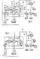
- FIG. 1 shows a first control device in a schematic representation
- FIG. 2 shows a second control device
- FIGS. 3 and 4 show further exemplary embodiments.
- the hydraulic control device is used to supply an injection unit 11 of a plastic injection molding machine (not shown).
- the injection unit 11 has, in a manner known per se, an injection cylinder 12 for the longitudinal movement of a plasticizing screw 13 and a hydraulic motor 14 for its rotary movement.
- An adjustable pump 15 is used to provide the required pressure medium, which draws pressure medium from a tank 16 and displaces it into a delivery line 17. This leads to a 3/2-way valve 18, from where a line leads to a pressure chamber 20 of the injection cylinder.
- the cartridge valve 18 is used to supply pressure medium to the pressure chamber 20.
- a line 22 also leads from the second pressure chamber 21, which is designed as an annular space, to a 3/2 cartridge valve 24.
- An electromagnetically actuated control valve 25 is used to control the valve 24, and the control valve 18 is used to control it a control valve 26 of the same type, upstream of which a flow limiting valve 27 is connected.
- the cartridge valve is used to supply pressure medium to the pressure chamber 21.
- the pump 15 has, in a known manner, two diametrically opposed actuating pistons 29, 30 which act on the adjusting member 31 thereof.
- the actuating piston 30 has a substantially smaller area than the actuating piston 29.
- An auxiliary pump 32 is used to provide the pressure medium required for adjusting the pump, which also draws pressure medium from the tank 16 and displaces it in two lines 33, 34.
- the line 34 leads to a 4/4 control valve 35, which controls the pressure medium to the actuating pistons 29, 30.
- a line 36 leads from the actuating piston 30 and a line 37 leads from the actuating piston 29 to the control valve 35. This is actuated against the force of a spring by an electromagnet 40, which is controlled by an electronic control device 45.
- a travel sensor 42 is coupled to the control valve 35 and registers the position of the control valve or its control slide.
- the actuating piston 29 is also provided with a displacement sensor 43, which inputs its values to an amplifier 41.
- the position of the injection cylinder (actual value) is fed back to the electronic control unit 45 via a displacement measuring system 46 arranged on the injection cylinder 11 via an electrical line 47 and the actual speed of the hydraulic motor 14 via a tachometer generator 66 via a line 67.
- the control unit 45 has a control amplifier, which Setpoints are compared and adjusted using the program inputs 45 'and 45 "for the hydraulic motor 14 and the injection cylinder 12 with the corresponding actual values.
- a line 50 is connected to the delivery line 17, from which a branch line 51 leads on the one hand to the cartridge valve 24 and on the other hand to the control valve 25. This is connected to the cartridge valve via a control line 52. Furthermore, a line 53 leads from the built-in valve 24 to the built-in valve 18; a line 54 leading to the tank 16 is connected to the line 53 via a check valve 55. The line 33 coming from the auxiliary pump 32 ends at the control valve 26. A line 57 is connected to this, from which on the one hand a line 58 branches off and leads to the built-in valve 18 and on the other hand a line 59 is connected which leads to an electromagnetically actuated directional valve 60.
- a line 61 is connected to the line 50, which leads on the one hand to a 2-way cartridge 63 and on the other hand to an electromagnetically actuated pilot valve 64. With the help of this the cartridge 63 can be brought into the control position.
- a line 65 leads from the outlet of the cartridge 63 to the hydraulic motor 14, which is coupled to a tachometer generator 66, from which the electrical line 67 leads to the electronic control unit 56.
- the line 59 ends at the directional control valve 60.
- a line 71 leads from the directional control valve 60 to a pressure valve 72, whereby a connection to the pressure control valve 69 is established. Its pressure chamber is connected to a pilot valve 74 via a line 73. From the pressure sensor 48 connected to the pressure chamber 20 of the injection cylinder, an electrical line 49 leads to an electrical signal processing 68, to which the respective process pressures in the pressure chamber 20 on the injection cylinder (injection pressure, back pressure, holding pressure) are entered via an electronic setpoint input 70 via electronics 68. This signals the pressures mentioned to a proportional pressure control valve 69.
- the control device works as follows: The directional control valves 60 and 26 are switched for the injection of plastic through the injection cylinder. As a result, the built-in valve 18 is brought into such a position that pressure medium flows from the line 17 via the line into the pressure chamber 20. The injection cylinder 12 is thereby extended at the preselected injection speed (filling phase). The outflow of pressure medium from the pressure chamber 21 takes place via the built-in valve 24 and the lines 53, 54 and the check valve 55 to the container. After the filling process has ended, the quasi-static phase follows. When the setpoint injection pressure programmed by the electronics on the pressure control valve 69 is reached, the built-in valve 18 is brought into the pressure control position.
- the pressure medium required for pressure control to adjust the built-in valve 18 is metered in via the flow control valve 27.
- the cartridge valve 18 then assumes a corresponding flow position.
- the pressure sensor 48 gives a signal for the change from spray pressure to holding pressure. This signal also causes an adjustment of the control valve 35 via the electronic control unit 45, which now adjusts the pump 15 in such a way that it produces the pressure medium flow that is required for the hold pressure control.
- the system pressure is at maximum system pressure via the pilot valve 74.
- the cartridge 63 By actuating the pilot valve 64, the cartridge 63 is opened so that pressure medium from the line 50 can also flow to the hydraulic motor 14 via the line 65. Its speed is also fed back from the tachometer generator via the electrical line 67 into the electronic control unit 45. This also affects the position of the control valve 35 in such a way that the setpoint and actual value of the speed are corrected.
- the speed of the hydraulic motor 14 can be continuously adjusted by the pump 15.
- the simultaneous back pressure control is also carried out by the built-in valve 18.
- the dynamic pressure values are continuously adjustable from zero bar.
- the system is secured with maximum pressure at the pressure relief valve 72 via the pilot valve 74.
- the injection cylinder 12 is moved to the right by the external force of the melt.
- the flow of pressure medium flowing out of the pressure chamber 20 is brought to the preselectable back pressure with the built-in valve 18 for the purpose of homogeneity of the melt.
- the pressure medium flow flowing out of the built-in valve 18 is slightly biased by the check valve 55. This ensures that the pressure chamber 21 on the injection cylinder is refilled via the built-in valve 24.
- This is set in the rest of the spraying process with the aid of the control valve 25 so that pressure medium can flow out of the pressure chamber 21. It is used for the decompression function, i.e. then when the screw 13 is reset.
- the pump 15 works as an actuator in a closed control loop with the injection cylinder 12 for positioning and injection speed (control pressure) and with the hydraulic motor for constant speed regardless of load pressure and other disturbance variables.
- variable displacement pump Depending on the requirements for the dynamics of the spraying process, the following applications are possible for the variable displacement pump:
- the pump 15 delivers a volume flow that is slightly greater than that required for the programmed injection speed.
- the system pressure is adapted to the load pressure via the directional valve 60 and the differential pressure valve 13.
- variable pump is fully swiveled in and acts as a constant pump.
- control line 71 and via the directional control valve 60 and the differential pressure valve 13 a pilot-controlled 3-way flow control system is implemented.
- variable pump is fully swung out and acts as a constant pump.
- the remaining amount of pressure medium flows through the pressure valve 72 to the tank under maximum pressure.
- the exemplary embodiment according to FIG. 2 differs from the previous one in that the control loop is formed from the injection cylinder 11 and the built-in valve 18, which form a closed control loop. There is also an additional source of pressure medium if a particularly large amount of pressure medium is necessary.
- goods in which the control valve 26 and the flow control valve 27 are necessary for controlling the built-in valve 18, this function is performed here by an electromagnetically actuated proportional valve 80 with electrical signal input 81. This is a signal supplied by a displacement sensor 82 which is in operative connection with the cartridge valve, ie the position of the built-in valve is signaled via the position encoder 82 of the electrical input.
- the displacement measuring system 46 on the injection cylinder 11 is now not in operative connection with the electronic control unit 45, but, depending on the position of a switch 83, with the pressure sensor 48 or the electrical signal input 81.
- a differential pressure valve 83 for additional control of the built-in valve 18 there is also a differential pressure valve 83 and the directional control valve 60 of the previous embodiment is necessary.
- a control line 85 leads from the differential pressure valve 84 connected to the directional control valve 60 to the built-in valve 18.
- the electronic control unit 45 is now not entered the speed of the injection cylinder, but rather the setpoint for the delivery flow and, as before, the setpoint speed of the hydraulic motor 14.
- a line 87 runs from the delivery line 17 via a control valve 88 to a pressure accumulator 89 with an additional volume of pressure medium.
- two pressure switches 90 and 91 are provided, which are connected to a line 92.
- a pressure relief valve 94 is arranged in a line 93 running parallel thereto.
- the cartridge valve 18 acts as an actuator in the position-speed and pressure control loop.
- the following applications for the pump 15 are possible in accordance with the requirements for the dynamics of the spraying process.
- the pump delivers a volume flow that is slightly higher than required for the programmed injection speed.
- the system pressure is closely matched to the load pressure by the control line 85 via the directional valve 60 and the differential pressure valve 84.
- the pump 15 provides its full delivery rate and thus acts as a constant pump.
- the control valve 60 and the differential pressure valve 84 via the control line 85 a pilot-controlled 3-way flow control system is implemented, by means of which the built-in valve 18 is regulated accordingly.
- the pump 15 in turn provides its maximum delivery rate and acts as a constant pump.
- the excess amount flows through the pressure relief valve 72 to the container.
- the spray process control can be additionally supplied with the aid of the pressure accumulator 81. If this is switched on by the electromagnetically actuated control valve 88 and the storage system reaches the maximum working pressure, the signal from the pressure switch 90 will set the variable pump to the minimum delivery quantity and the pressure at the pilot valve 69 to the minimum pressure. If this is reached in the pressure accumulator, then the pump 15 is set again to the maximum delivery rate via the pressure signal of the pressure switch 91.
- the adjustment device for the adjustable pump 15 is designed differently, i.e. a control valve 100 acts instead of the control valve 35.
- a control spring 101 acts on this, which is supported on the actuating piston 29.
- an extension 102 is formed, on which an angle lever 103 is articulated, on which a proportional magnet 104 acts. This in turn receives signals from the electronic control unit 45. In this way, a force comparison between the control spring 101 and the proportional magnet 54 is possible.
- a control line 105 which leads to a limiting valve 106, is also connected to the actuating piston 30.
- a pressure spring 107 acts on the one hand, and the pressure from a line 109 connected to the delivery line 17 via a control line 108.
- a control pressure medium flow flows from the delivery line 17 via the control line 110 and the throttle 113 and the control line 111 to the pressure regulating valve 69.
- the pressure drop created at the throttle 113 causes the limiting valve 106 to be adjusted. The pressure drop is determined by the spring 107 of the limit valve 106.
- the pump 15 can be operated by the limiting valve 106 in a pressure and current-controlled manner. This is possible in that a connecting line 114 leads from line 112 to a line 115 on which directional control valve 60 is located. In this case, the line 111 does not lead to the valve 60.
- the closed control circuit comprising the pump 15 and the hydraulic motor 14 with the plasticizing function with the longest cycle time remains unchanged as an energy-saving drive.
- the flow rate is adapted to the programmed injection speed and the speed of the hydraulic motor. This makes the drive energy-saving.
Landscapes
- Engineering & Computer Science (AREA)
- Manufacturing & Machinery (AREA)
- Mechanical Engineering (AREA)
- Injection Moulding Of Plastics Or The Like (AREA)
Claims (9)
Priority Applications (1)
| Application Number | Priority Date | Filing Date | Title |
|---|---|---|---|
| AT85104770T ATE57869T1 (de) | 1984-05-16 | 1985-04-19 | Hydraulische steuereinrichtung fuer die einspritzeinheit einer kunstoffspritzgiessmaschine. |
Applications Claiming Priority (2)
| Application Number | Priority Date | Filing Date | Title |
|---|---|---|---|
| DE19843418141 DE3418141A1 (de) | 1984-05-16 | 1984-05-16 | Hydraulische steuereinrichtung fuer die einspritzeinheit einer kunststoff-spritzgiessmaschine |
| DE3418141 | 1984-05-16 |
Publications (4)
| Publication Number | Publication Date |
|---|---|
| EP0163884A2 EP0163884A2 (fr) | 1985-12-11 |
| EP0163884A3 EP0163884A3 (en) | 1988-09-07 |
| EP0163884B1 true EP0163884B1 (fr) | 1990-10-31 |
| EP0163884B2 EP0163884B2 (fr) | 1999-12-15 |
Family
ID=6235987
Family Applications (1)
| Application Number | Title | Priority Date | Filing Date |
|---|---|---|---|
| EP85104770A Expired - Lifetime EP0163884B2 (fr) | 1984-05-16 | 1985-04-19 | Dispositif de commande hydraulique pour l'unité d'injection d'une machine d'injection de matières plastiques |
Country Status (3)
| Country | Link |
|---|---|
| EP (1) | EP0163884B2 (fr) |
| AT (1) | ATE57869T1 (fr) |
| DE (2) | DE3418141A1 (fr) |
Cited By (1)
| Publication number | Priority date | Publication date | Assignee | Title |
|---|---|---|---|---|
| CN104816444A (zh) * | 2015-04-17 | 2015-08-05 | 广州云雁电气科技有限公司 | 一种智慧型异步伺服节能一体机及其控制方法 |
Families Citing this family (4)
| Publication number | Priority date | Publication date | Assignee | Title |
|---|---|---|---|---|
| DE3606366C2 (de) * | 1986-02-27 | 1997-10-09 | Bosch Gmbh Robert | Hydraulische Steuereinrichtung für eine Spritzgießmaschine |
| ATE208779T1 (de) * | 1993-07-02 | 2001-11-15 | Bayer Ag | Substituierte spiroheterocyclische 1h-3-aryl- pyrrolidin-2,4-dion-derivate, verfahren zu deren herstellung und deren verwendung als schädlingsbekämpfungsmittel |
| JP4376841B2 (ja) * | 2005-09-08 | 2009-12-02 | 日精樹脂工業株式会社 | 射出成形機及びその制御方法 |
| CN114311575B (zh) * | 2021-12-30 | 2024-03-29 | 阿托斯(上海)液压有限公司 | 一种基于双闭环pid调节的注塑机背压控制装置及方法 |
Family Cites Families (6)
| Publication number | Priority date | Publication date | Assignee | Title |
|---|---|---|---|---|
| DE2257406A1 (de) * | 1972-11-23 | 1974-06-12 | Philips Patentverwaltung | Verfahren und anordnung zur konstanthaltung der dosiermenge bei kunststoffverarbeitenden spritzgiessmaschinen |
| DE2523303C3 (de) * | 1975-05-27 | 1980-04-24 | Kloeckner-Werke Ag, 4100 Duisburg | Hydraulische Steuervorrichtung für die Einspritzeinheit einer Kunststoff-Spritzgießmaschine zum Steuern unterschiedlicher Hydraulikdrücke |
| DE2951948A1 (de) * | 1979-12-22 | 1981-07-02 | Robert Bosch Gmbh, 7000 Stuttgart | Hydraulische steuervorrichtung fuer die einspritzeinheit einer kunststoff-spritzgiessmaschine zum steuern unterschiedlicher hydraulikdruecke |
| SU937201A1 (ru) * | 1980-12-30 | 1982-06-23 | Центральное проектно-конструкторское бюро кузнечно-прессового машиностроения | Способ автоматического управлени процессом пластикации при изготовлении изделий из пластмасс методом лить под давлением |
| JPS5838134A (ja) * | 1981-08-31 | 1983-03-05 | Daikin Ind Ltd | 射出シリンダの速度制御装置 |
| DE3404927C2 (de) * | 1984-02-11 | 1994-05-05 | Bosch Gmbh Robert | Hydraulische Steuereinrichtung für die Einspritzeinheit einer Kunststoff-Spritzgießmaschine |
-
1984
- 1984-05-16 DE DE19843418141 patent/DE3418141A1/de not_active Withdrawn
-
1985
- 1985-04-19 DE DE8585104770T patent/DE3580305D1/de not_active Expired - Lifetime
- 1985-04-19 AT AT85104770T patent/ATE57869T1/de not_active IP Right Cessation
- 1985-04-19 EP EP85104770A patent/EP0163884B2/fr not_active Expired - Lifetime
Cited By (1)
| Publication number | Priority date | Publication date | Assignee | Title |
|---|---|---|---|---|
| CN104816444A (zh) * | 2015-04-17 | 2015-08-05 | 广州云雁电气科技有限公司 | 一种智慧型异步伺服节能一体机及其控制方法 |
Also Published As
| Publication number | Publication date |
|---|---|
| EP0163884A3 (en) | 1988-09-07 |
| DE3580305D1 (de) | 1990-12-06 |
| ATE57869T1 (de) | 1990-11-15 |
| EP0163884A2 (fr) | 1985-12-11 |
| DE3418141A1 (de) | 1985-11-21 |
| EP0163884B2 (fr) | 1999-12-15 |
Similar Documents
| Publication | Publication Date | Title |
|---|---|---|
| DE3249820C2 (fr) | ||
| EP0164602B2 (fr) | Dispositif pour le réglage de la pression et du débit d'une pompe réglable | |
| DE10342037A1 (de) | Steueranordnung und Verfahren zur Druckmittelversorgung von zumindest zwei hydraulischen Verbrauchern | |
| EP0185984A2 (fr) | Dispositif hydraulique pour le groupe d'injection d'une machine de moulage par injection de matière plastique | |
| EP0465474B1 (fr) | Agencement de commande de pompes a liquides epais a deux cylindres | |
| DE2603563C2 (de) | Steuereinrichtung für ein aus mindestens zwei Pumpen bestehendes Pumpen-Aggregat | |
| DE19615593A1 (de) | Hydrostatisches Antriebssystem | |
| EP0163884B1 (fr) | Dispositif de commande hydraulique pour l'unité d'injection d'une machine d'injection de matières plastiques | |
| DE1555480B2 (de) | Steuereinrichtung fuer ein hydrostatisches getriebe insbesondere fuer kraftfahrzeuge | |
| DE3119095C2 (de) | Steuervorrichtung für den hydraulischen Kreislauf einer Kunststoff-Spritzgießmaschine | |
| DE3443354A1 (de) | Hydraulikanlage | |
| DE2951948C2 (fr) | ||
| DE2410402C3 (de) | Brennstoffversorgungsanlage für ein Gasturbinenwerk | |
| DE3702002A1 (de) | Steuervorrichtung fuer ein hydrostatisches getriebe fuer wenigstens zwei verbraucher | |
| EP0241870B1 (fr) | Dispositif de commande hydraulique | |
| DE3844401C2 (de) | Regeleinrichtung für eine Verstellpumpe | |
| DE3404927C2 (de) | Hydraulische Steuereinrichtung für die Einspritzeinheit einer Kunststoff-Spritzgießmaschine | |
| DE10225691A1 (de) | Stellpumpe mit elektrohydraulischer Proportionalverstellung im geschlossenen Kreislauf | |
| DE3528096A1 (de) | Steuereinrichtung fuer ein antriebssystem mit eingepraegtem druck | |
| DE112004002768B4 (de) | Hydraulisches Steuersystem | |
| DE3113933C2 (fr) | ||
| DE4140423A1 (de) | Vorrichtung zur einstellung des arbeitsfluessigkeitsdruckes | |
| WO2006066548A1 (fr) | Dispositif de commande hydraulique | |
| DE3112561C2 (de) | Steuervorrichtung für eine Flüssigkeitspumpe mit verstellbarem Fördervolumen | |
| DE4340873A1 (de) | Hydraulikanlage für ein Kraftfahrzeug |
Legal Events
| Date | Code | Title | Description |
|---|---|---|---|
| PUAI | Public reference made under article 153(3) epc to a published international application that has entered the european phase |
Free format text: ORIGINAL CODE: 0009012 |
|
| 17P | Request for examination filed |
Effective date: 19850419 |
|
| AK | Designated contracting states |
Designated state(s): AT DE FR IT |
|
| PUAL | Search report despatched |
Free format text: ORIGINAL CODE: 0009013 |
|
| AK | Designated contracting states |
Kind code of ref document: A3 Designated state(s): AT DE FR IT |
|
| 17Q | First examination report despatched |
Effective date: 19900404 |
|
| GRAA | (expected) grant |
Free format text: ORIGINAL CODE: 0009210 |
|
| AK | Designated contracting states |
Kind code of ref document: B1 Designated state(s): AT DE FR IT |
|
| REF | Corresponds to: |
Ref document number: 57869 Country of ref document: AT Date of ref document: 19901115 Kind code of ref document: T |
|
| ET | Fr: translation filed | ||
| REF | Corresponds to: |
Ref document number: 3580305 Country of ref document: DE Date of ref document: 19901206 |
|
| ITF | It: translation for a ep patent filed |
Owner name: STUDIO JAUMANN |
|
| ITTA | It: last paid annual fee | ||
| PLBI | Opposition filed |
Free format text: ORIGINAL CODE: 0009260 |
|
| 26 | Opposition filed |
Opponent name: MANNESMANN REXROTH GMBH Effective date: 19910731 Opponent name: BATTENFELD GMBH Effective date: 19910731 |
|
| RAP4 | Party data changed (patent owner data changed or rights of a patent transferred) |
Owner name: ROBERT BOSCH GMBH |
|
| APCC | Communication from the board of appeal sent |
Free format text: ORIGINAL CODE: EPIDOS OBAPO |
|
| APCC | Communication from the board of appeal sent |
Free format text: ORIGINAL CODE: EPIDOS OBAPO |
|
| APAC | Appeal dossier modified |
Free format text: ORIGINAL CODE: EPIDOS NOAPO |
|
| PLAW | Interlocutory decision in opposition |
Free format text: ORIGINAL CODE: EPIDOS IDOP |
|
| PLAW | Interlocutory decision in opposition |
Free format text: ORIGINAL CODE: EPIDOS IDOP |
|
| PUAH | Patent maintained in amended form |
Free format text: ORIGINAL CODE: 0009272 |
|
| STAA | Information on the status of an ep patent application or granted ep patent |
Free format text: STATUS: PATENT MAINTAINED AS AMENDED |
|
| 27A | Patent maintained in amended form |
Effective date: 19991215 |
|
| AK | Designated contracting states |
Kind code of ref document: B2 Designated state(s): AT DE FR IT |
|
| ITF | It: translation for a ep patent filed |
Owner name: STUDIO JAUMANN P. & C. S.N.C. |
|
| ET3 | Fr: translation filed ** decision concerning opposition | ||
| PGFP | Annual fee paid to national office [announced via postgrant information from national office to epo] |
Ref country code: FR Payment date: 20000420 Year of fee payment: 16 |
|
| PG25 | Lapsed in a contracting state [announced via postgrant information from national office to epo] |
Ref country code: FR Free format text: THE PATENT HAS BEEN ANNULLED BY A DECISION OF A NATIONAL AUTHORITY Effective date: 20010430 |
|
| REG | Reference to a national code |
Ref country code: FR Ref legal event code: ST |
|
| PGFP | Annual fee paid to national office [announced via postgrant information from national office to epo] |
Ref country code: AT Payment date: 20020422 Year of fee payment: 18 |
|
| PGFP | Annual fee paid to national office [announced via postgrant information from national office to epo] |
Ref country code: DE Payment date: 20020528 Year of fee payment: 18 |
|
| PG25 | Lapsed in a contracting state [announced via postgrant information from national office to epo] |
Ref country code: AT Free format text: LAPSE BECAUSE OF NON-PAYMENT OF DUE FEES Effective date: 20030419 |
|
| PG25 | Lapsed in a contracting state [announced via postgrant information from national office to epo] |
Ref country code: DE Free format text: LAPSE BECAUSE OF NON-PAYMENT OF DUE FEES Effective date: 20031101 |
|
| APAH | Appeal reference modified |
Free format text: ORIGINAL CODE: EPIDOSCREFNO |