EP0163815B1 - Thrust bearing - Google Patents
Thrust bearing Download PDFInfo
- Publication number
- EP0163815B1 EP0163815B1 EP85102263A EP85102263A EP0163815B1 EP 0163815 B1 EP0163815 B1 EP 0163815B1 EP 85102263 A EP85102263 A EP 85102263A EP 85102263 A EP85102263 A EP 85102263A EP 0163815 B1 EP0163815 B1 EP 0163815B1
- Authority
- EP
- European Patent Office
- Prior art keywords
- oil
- shoe
- base ring
- distribution groove
- edge
- Prior art date
- Legal status (The legal status is an assumption and is not a legal conclusion. Google has not performed a legal analysis and makes no representation as to the accuracy of the status listed.)
- Expired
Links
- 230000000694 effects Effects 0.000 claims description 4
- 238000005461 lubrication Methods 0.000 description 3
- 239000000314 lubricant Substances 0.000 description 2
- 230000000052 comparative effect Effects 0.000 description 1
- 230000009977 dual effect Effects 0.000 description 1
- 238000004134 energy conservation Methods 0.000 description 1
- 235000003642 hunger Nutrition 0.000 description 1
- 238000004519 manufacturing process Methods 0.000 description 1
- 230000037351 starvation Effects 0.000 description 1
Images


Classifications
-
- F—MECHANICAL ENGINEERING; LIGHTING; HEATING; WEAPONS; BLASTING
- F16—ENGINEERING ELEMENTS AND UNITS; GENERAL MEASURES FOR PRODUCING AND MAINTAINING EFFECTIVE FUNCTIONING OF MACHINES OR INSTALLATIONS; THERMAL INSULATION IN GENERAL
- F16C—SHAFTS; FLEXIBLE SHAFTS; ELEMENTS OR CRANKSHAFT MECHANISMS; ROTARY BODIES OTHER THAN GEARING ELEMENTS; BEARINGS
- F16C17/00—Sliding-contact bearings for exclusively rotary movement
- F16C17/04—Sliding-contact bearings for exclusively rotary movement for axial load only
- F16C17/06—Sliding-contact bearings for exclusively rotary movement for axial load only with tiltably-supported segments, e.g. Michell bearings
Definitions
- the invention relates to a thrust bearing for use with a shaft having a collar mounted thereon, comprising a base ring, a thrust bearing shoe having a leading edge connected to a trailing edge by an inner diameter edge and an outer diameter edge, said shoe having a working face with a bearing liner on its surface, a series of shoes positioned on the base ring, shoe pivot means on each shoe allowing the shoe to pivot in any direction, an oil distribution groove formed in the working face near the leading edge of the shoe and extending radially for substantially the entire distance between the inner and outer diameter edges of the shoe, said oil distribution groove having an inner end and an outer end connected by a leading edge and a trailing edge, a bleed groove, an oil supply hole extending axially through the base ring, an oil feed tube connected between the oil supply hole and one feed of the oil distribution groove, said oil feed tube having a near end with a ball shape and a far end with a ball shape, a first socket formed in the shoe and connected to the oil distribution groove for receiving the near end of
- Such thrust bearings as known from US-A-2507021 are provided with a base ring on which is mounted a series of bearing shoes which are positioned so as to face the side of a rotating collar mounted on a rotating shaft.
- Lubrication is provided to the thrust bearing by feeding oil into passageways in the base ring that lead to the shoes, and flooding the inside of the base ring and the shoes with oil.
- this system of lubrication consumed a large quantity of oil and created a large power loss.
- a thrust bearing of the generic kind which comprises a bleed groove extending radially from the inner end of the oil distribution groove to the inner diameter edge of the shoe for supplying oil to the inner diameter area of the shoe downstream of the bleed groove which downstream inner diameter area would otherwise be starved of oil by the centrifugal inertia effects of rotating the collar, an oil supply hole extending near the outer diameter edge of the base ring, an oil feed tube connected to the outer end of the oil distribution groove near the outer diameter edge of the shoe, said near end of the oil feed tube having an annular recess with an 0-ring seated in the recess, said far end of the oil feed tube having an annular recess with an 0-ring seated in the recess, said first socket connected to the oil distribution groove at its outer end for receiving its 0-ring to seal the tube against oil leaks, said second socket receiving the 0-ring of the far end to seal the tube against oil leaks, and shoulders formed at the openings to said sockets for retaining the ends of the tube
- the thrust bearing may include a series of upper and lower leveling plates for equalizing the load on the series of shoes.
- said trailing edge of the oil distribution groove can be a chamfered edge for more easily allowing oil to flow from the oil distribution groove to cover the shoe working face with oil.
- the thrust bearing of the invention conserves energy by reducing the oil flow and consumed less power. It uses less lubricant, thus requiring a smaller pump and other auxiliary equipment.
- the thrust bearing is efficient; it applies the oil lubricant where it is needed and used, at the working face of the shoe, and does not flood the base ring, leveling plates, and shoes as in conventional thrust bearings.
- the thrust bearing is such an efficient bearing that it runs cooler since the oil is applied just where it is used and it runs cooler so that it can carry higher loads.
- the thrust bearing is smaller and easier to manufacture than the thrust bearing of US-A-2,507,021.
- the height of the bearing is defined as the axial distance between the bottom of the base ring and the working face of the shoe.
- the width of a shoe is defined as the radial distance along a shoe from the outer diameter edge to the inner diameter edge, and the length of a shoe is defined as the circumferential distance between the leading edge and the trailing edge of the shoe.
- the thrust bearing does not have the radial passage as shown in US-A-2,507,021, so the thrust bearing has a smaller height than the thrust bearing of this prior art.
- a thrust bearing having a series of shoes with a leading edge distribution groove and a bleed groove leading to the inside diameter edge of the shoe so as to prevent--oil starvation of the inner diameter edge area of the shoe caused by centrifugal forces, and an oil feed tube connected between the outer end of the oil distribution groove and an oil supply hole in the base ring, which oil feed tube is provided with O-rings that seal the oil supply system against leakage and directs the oil against the working faces of the shoes where it is needed and prevents the oil from leaking into areas where it is not needed or useful.
- the oil feed tube is positioned near the outer diameter edge of the thrust bearing and is connected to an axially drilled oil supply hole in the base ring, so as to eliminate radial oil supply passageways in the base ring and so as to reduce the overall height of the base ring between the face of the shoes and the far end of the base ring.
- the thrust bearing 11 for the use with a shaft 13 having a collar 15 mounted on shaft 13 and rotatable therewith.
- the thrust bearing 11 comprises a base ring 17, and a series of shoes 19 positioned around the base ring 17.
- Each shoe 19 has a leading edge 21 connected to a trailing edge 23 by an inner diameter edge 25 and an outer diameter edge 27.
- the direction of rotation of collar 15 is indicated by an arrow 29.
- Each shoe 19 includes a working face 31 with a bearing liner 33 on its surface.
- a shoe pivot 35 is mounted on each shoe 19 so as to face away from the working face 31 of the shoe 19, and is provided with a spherical surface to allow the shoe 19 to pivot freely in any direction to conform to the side surfaces of the collar 15.
- An oil distribution groove 37 is formed in the working face 31 of the shoe 19 near the leading edge 21 of the shoe and extends radially for substantially the entire distance between inner diameter edge 25 and outer diameter edge 27 of the shoe 19. Oil distribution groove 37 has an inner end 39 and an outer end 41 connected together by a leading edge 43 and a trailing edge 45.
- a bleed groove 47 extends radially from the inner end 39 of the oil distribution groove 37 to the inner diameter edge 25 of the shoe 19 for supplying oil to the inner diameter edge area of the shoe 19 downstream of the bleed groove 47, which downstream inner diameter area would otherwise be starved of oil by the centrifugal inertial effects of rotating the collar 15.
- Trailing edge 45 of oil distribution groove 37 is chamfered so as to provide a chamfered edge for more easily allowing oil to flow from the oil distribution groove 37 to cover the shoe working face 31 with oil during the rotation of shaft 13 and collar 15.
- An oil supply hole 49 is drilled through base ring 17 and extends axially through the base ring near the outer diameter edge 27 of base ring 17.
- An oil feed tube 51 is connected between the oil supply hole 49 and the outer end 41 of the oil distribution groove 37 near the outer diameter edge 27 of the shoe 19.
- the oil feed tube 51 is provided at its near end 53 with a ball shape 55 and an annular recess 57 with an O-ring 59 seated in the recess 57.
- the oil feed tube 51 is also provided at its far end 61 with a ball shape 63 and an annular recess 65 with an O-ring 67 seated in the recess 65.
- a socket 71 is formed in the shoe 19 and is connected to the oil distribution groove 37 at its outer end 41 for receiving the near end 53 of oil feed tube 51 and its O-ring 59 to seal the tube 51 against oil leaks.
- a socket 73 is formed in base ring 17 for receiving the far end 61 of oil feed tube 51 and its 0-ring 67 to seal the tube 51 against oil leaks.
- a shoulder 75 is formed in the opening of socket 71 for retaining near end 53 of tube 51 in the socket.
- a shoulder 77 is formed at the opening to socket 73 for retaining the far end 61 of oil feed tube 51 in the socket 73.
- the oil feed tube 51 performs a dual function. Besides supplying oil from oil supply hole 49 to oil distribution groove 37 and preventing oil leakage from the tube 51 because of the effect of the O-rings 59 and 67, the oil feed tube 51 also assists in retaining the shoe 19 in connection with base ring 17.
- retainer pins 79 which extend radially from the shoe 19 into an annular groove 81 in the base ring 17.
- upper leveling plates 83 and lower leveling plates 85 which are placed alternately around base ring 17 and in an annular groove 87.
- Lower leveling plates 85 are positioned by axially directed lower leveling plate retainer dowels 89, and upper leveling plates 83 are positioned by upper leveling plate retainer set screws 91 which are radially directed.
- Shoe pivots 35 bear on the upper leveling plates 83, and the action of the alterately placed leveling plates 83, 85 serves to distribute the load evenly among the shoes 19.
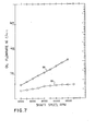
- line 93 indicates the oil flow rate versus shaft speed of a standard thrust bearing
- line 95 indicates the oil flow rate versus shaft speed of the thrust bearing constructed in accordance with this invention.
- the oil flow rate ranges from about 53 I/min at 4000 RPM shaft speed to about 155 I/min at about 12000 RPM shaft speed.
- the thrust bearing of the invention ranges from about 30 I/min at 4000 RPM to about 56 I/min at 12000 RPM.
- line 97 shows results of the tests of the standard bearing
- line 99 shows the results of a comparable bearing constructed in accordance with this invention.
- the standard bearing ranges from a total power loss of about 2 kW at 4000 RPM to about 230 kW at 12000 RPM
- the thrust bearing of the present invention ranges from a loss of about 18 kW at 4000 RPM to about 140 kW at 12000 RPM, which is a difference of 90 kW at 12000 RPM.
- Fig. 9 shows a graph which plots temperature in degrees Celsius against shaft speed in RPM of a standard thrust bearing shown by line 101 versus a comparative bearing of the present invention shown by line 103.
- the lines show that the thrust bearing of the invention is cooler than the standard bearing at speeds between 4000 RPM and a little above 10000 RPM.
Landscapes
- Engineering & Computer Science (AREA)
- General Engineering & Computer Science (AREA)
- Mechanical Engineering (AREA)
- Sliding-Contact Bearings (AREA)
Description
- The invention relates to a thrust bearing for use with a shaft having a collar mounted thereon, comprising a base ring, a thrust bearing shoe having a leading edge connected to a trailing edge by an inner diameter edge and an outer diameter edge, said shoe having a working face with a bearing liner on its surface, a series of shoes positioned on the base ring, shoe pivot means on each shoe allowing the shoe to pivot in any direction, an oil distribution groove formed in the working face near the leading edge of the shoe and extending radially for substantially the entire distance between the inner and outer diameter edges of the shoe, said oil distribution groove having an inner end and an outer end connected by a leading edge and a trailing edge, a bleed groove, an oil supply hole extending axially through the base ring, an oil feed tube connected between the oil supply hole and one feed of the oil distribution groove, said oil feed tube having a near end with a ball shape and a far end with a ball shape, a first socket formed in the shoe and connected to the oil distribution groove for receiving the near end of the oil feed tube, and a second socket formed in the base ring receiving the far end of the oil feed tube.
- Such thrust bearings as known from US-A-2507021 are provided with a base ring on which is mounted a series of bearing shoes which are positioned so as to face the side of a rotating collar mounted on a rotating shaft. Lubrication is provided to the thrust bearing by feeding oil into passageways in the base ring that lead to the shoes, and flooding the inside of the base ring and the shoes with oil. However, this system of lubrication consumed a large quantity of oil and created a large power loss.
- Accordingly, it has been desired to reduce the amount of oil flow in a thrust bearing lubrication system, to increase the load carrying capabilities, and to lower the power loss, in the interest of energy conservation. Besides reducing the amount of oil used, and lowering the power loss, such a system would desirably use a smaller pump and other auxiliary equipment and be more efficient.
- It is an object of this invention to provide a thrust bearing which increases the load carrying capacity, uses less oil, consumes less power, uses smaller auxiliary equipment, and is more efficient than the thrust bearings of the prior art.
- This object is accomplished by providing a thrust bearing of the generic kind which comprises a bleed groove extending radially from the inner end of the oil distribution groove to the inner diameter edge of the shoe for supplying oil to the inner diameter area of the shoe downstream of the bleed groove which downstream inner diameter area would otherwise be starved of oil by the centrifugal inertia effects of rotating the collar, an oil supply hole extending near the outer diameter edge of the base ring, an oil feed tube connected to the outer end of the oil distribution groove near the outer diameter edge of the shoe, said near end of the oil feed tube having an annular recess with an 0-ring seated in the recess, said far end of the oil feed tube having an annular recess with an 0-ring seated in the recess, said first socket connected to the oil distribution groove at its outer end for receiving its 0-ring to seal the tube against oil leaks, said second socket receiving the 0-ring of the far end to seal the tube against oil leaks, and shoulders formed at the openings to said sockets for retaining the ends of the tube in the sockets, and a retainer pin extending radially from the shoe into an annular groove in the base ring to assist in retaining the shoe on the base ring.
- The thrust bearing may include a series of upper and lower leveling plates for equalizing the load on the series of shoes.
- Further, said trailing edge of the oil distribution groove can be a chamfered edge for more easily allowing oil to flow from the oil distribution groove to cover the shoe working face with oil.
- The thrust bearing of the invention conserves energy by reducing the oil flow and consumed less power. It uses less lubricant, thus requiring a smaller pump and other auxiliary equipment. The thrust bearing is efficient; it applies the oil lubricant where it is needed and used, at the working face of the shoe, and does not flood the base ring, leveling plates, and shoes as in conventional thrust bearings.
- The thrust bearing is such an efficient bearing that it runs cooler since the oil is applied just where it is used and it runs cooler so that it can carry higher loads.
- The thrust bearing is smaller and easier to manufacture than the thrust bearing of US-A-2,507,021.
- The height of the bearing is defined as the axial distance between the bottom of the base ring and the working face of the shoe. The width of a shoe is defined as the radial distance along a shoe from the outer diameter edge to the inner diameter edge, and the length of a shoe is defined as the circumferential distance between the leading edge and the trailing edge of the shoe.
- The thrust bearing does not have the radial passage as shown in US-A-2,507,021, so the thrust bearing has a smaller height than the thrust bearing of this prior art.
- Thus, according to the invention, a thrust bearing is provided having a series of shoes with a leading edge distribution groove and a bleed groove leading to the inside diameter edge of the shoe so as to prevent--oil starvation of the inner diameter edge area of the shoe caused by centrifugal forces, and an oil feed tube connected between the outer end of the oil distribution groove and an oil supply hole in the base ring, which oil feed tube is provided with O-rings that seal the oil supply system against leakage and directs the oil against the working faces of the shoes where it is needed and prevents the oil from leaking into areas where it is not needed or useful. The oil feed tube is positioned near the outer diameter edge of the thrust bearing and is connected to an axially drilled oil supply hole in the base ring, so as to eliminate radial oil supply passageways in the base ring and so as to reduce the overall height of the base ring between the face of the shoes and the far end of the base ring.
- The further structural features of the thrust bearing according to the invention are described by way of example by means of annexed drawings.
- Fig. 1 is a view in elevation of a pair of thrust bearings constructed in accordance with this invention and positioned on each side of a rotating collar mounted on a shaft;
- Fig. 2 is a view looking at the faces of the shoes of one of the thrust bearings;
- Fig. 3 is a view in section taken as indicated by the lines and arrows 3-3 which appear in Fig. 2;
- Fig. 4 is an enlarged view in perspective of a bearing shoe which is adapted for use with a collar that is rotating in a clockwise direction, whereas the shoes shown in Fig. 2 are adapted for use with a collar that is rotating in a counterclockwise direction.
- Fig. 5 is a view in section taken as indicated by the lines and arrows 5-5 which appear in Fig. 4;
- Fig. 6 is a view in section taken as indicated by the lines and arrows 6-6 which appear in Fig. 4;
- Fig. 7 is a graph which compares oil flow rate against shaft speed of a standard 10: inch thrust bearing (Kingsbury's Guide To Equalizing Thrust Bearings, Catalog EQH), and a 10) inch thrust bearing constructed in accordance with this invention, using six-shoe bearings, 35 bar, bearing oil flows to load bearing.
- Fig. 8 is a graph which plots total power loss against shaft speed of the standard 10) inch thrust bearing against the 10s inch thrust bearing of the invention; and
- Fig. 9 is a graph which plots temperature against shaft speed of the standard 10) inch thrust bearing against the 101 inch thrust bearing of the invention, the hottest reported babbitt temperature being in the area of high film pressures.
- Turning now to the drawings, there is shown a thrust bearing 11 for the use with a
shaft 13 having acollar 15 mounted onshaft 13 and rotatable therewith. The thrust bearing 11 comprises abase ring 17, and a series ofshoes 19 positioned around thebase ring 17. - Each
shoe 19 has a leadingedge 21 connected to atrailing edge 23 by aninner diameter edge 25 and anouter diameter edge 27. The direction of rotation ofcollar 15 is indicated by anarrow 29. - Each
shoe 19 includes a workingface 31 with abearing liner 33 on its surface. - A
shoe pivot 35 is mounted on eachshoe 19 so as to face away from the workingface 31 of theshoe 19, and is provided with a spherical surface to allow theshoe 19 to pivot freely in any direction to conform to the side surfaces of thecollar 15. Anoil distribution groove 37 is formed in the workingface 31 of theshoe 19 near the leadingedge 21 of the shoe and extends radially for substantially the entire distance betweeninner diameter edge 25 andouter diameter edge 27 of theshoe 19.Oil distribution groove 37 has aninner end 39 and anouter end 41 connected together by a leadingedge 43 and atrailing edge 45. - A
bleed groove 47 extends radially from theinner end 39 of theoil distribution groove 37 to theinner diameter edge 25 of theshoe 19 for supplying oil to the inner diameter edge area of theshoe 19 downstream of thebleed groove 47, which downstream inner diameter area would otherwise be starved of oil by the centrifugal inertial effects of rotating thecollar 15. - Trailing
edge 45 ofoil distribution groove 37 is chamfered so as to provide a chamfered edge for more easily allowing oil to flow from theoil distribution groove 37 to cover theshoe working face 31 with oil during the rotation ofshaft 13 andcollar 15. - An
oil supply hole 49 is drilled throughbase ring 17 and extends axially through the base ring near theouter diameter edge 27 ofbase ring 17. - An
oil feed tube 51 is connected between theoil supply hole 49 and theouter end 41 of theoil distribution groove 37 near theouter diameter edge 27 of theshoe 19. Theoil feed tube 51 is provided at itsnear end 53 with a ball shape 55 and an annular recess 57 with an O-ring 59 seated in the recess 57. - The
oil feed tube 51 is also provided at itsfar end 61 with aball shape 63 and anannular recess 65 with an O-ring 67 seated in therecess 65. - A socket 71 is formed in the
shoe 19 and is connected to theoil distribution groove 37 at itsouter end 41 for receiving thenear end 53 ofoil feed tube 51 and its O-ring 59 to seal thetube 51 against oil leaks. - A
socket 73 is formed inbase ring 17 for receiving thefar end 61 ofoil feed tube 51 and its 0-ring 67 to seal thetube 51 against oil leaks. - A
shoulder 75 is formed in the opening of socket 71 for retaining nearend 53 oftube 51 in the socket. Similarly, a shoulder 77 is formed at the opening tosocket 73 for retaining the farend 61 ofoil feed tube 51 in thesocket 73. - The
oil feed tube 51 performs a dual function. Besides supplying oil fromoil supply hole 49 tooil distribution groove 37 and preventing oil leakage from thetube 51 because of the effect of the O-rings oil feed tube 51 also assists in retaining theshoe 19 in connection withbase ring 17. - Also assisting in retaining the
shoe 19 inring 17 are theretainer pins 79 which extend radially from theshoe 19 into anannular groove 81 in thebase ring 17. - Mounted between the
shoes 19 and thebase ring 17 in thrust bearing 11 are a series ofupper leveling plates 83 andlower leveling plates 85 which are placed alternately aroundbase ring 17 and in anannular groove 87.Lower leveling plates 85 are positioned by axially directed lower levelingplate retainer dowels 89, andupper leveling plates 83 are positioned by upper leveling plate retainer setscrews 91 which are radially directed. -
Shoe pivots 35 bear on theupper leveling plates 83, and the action of the alterately placedleveling plates shoes 19. - In Fig. 7,
line 93 indicates the oil flow rate versus shaft speed of a standard thrust bearing, andline 95 indicates the oil flow rate versus shaft speed of the thrust bearing constructed in accordance with this invention. In the standard bearing, the oil flow rate ranges from about 53 I/min at 4000 RPM shaft speed to about 155 I/min at about 12000 RPM shaft speed. - On the other hand, the thrust bearing of the invention ranges from about 30 I/min at 4000 RPM to about 56 I/min at 12000 RPM.
- In Fig. 8,
line 97 shows results of the tests of the standard bearing,line 99 shows the results of a comparable bearing constructed in accordance with this invention. The standard bearing ranges from a total power loss of about 2 kW at 4000 RPM to about 230 kW at 12000 RPM, while the thrust bearing of the present invention ranges from a loss of about 18 kW at 4000 RPM to about 140 kW at 12000 RPM, which is a difference of 90 kW at 12000 RPM. - Fig. 9 shows a graph which plots temperature in degrees Celsius against shaft speed in RPM of a standard thrust bearing shown by
line 101 versus a comparative bearing of the present invention shown byline 103. The lines show that the thrust bearing of the invention is cooler than the standard bearing at speeds between 4000 RPM and a little above 10000 RPM.
Claims (3)
characterized in that
Applications Claiming Priority (2)
| Application Number | Priority Date | Filing Date | Title |
|---|---|---|---|
| US06/617,721 US4501505A (en) | 1984-06-06 | 1984-06-06 | Thrust bearing |
| US617721 | 2000-07-17 |
Publications (3)
| Publication Number | Publication Date |
|---|---|
| EP0163815A2 EP0163815A2 (en) | 1985-12-11 |
| EP0163815A3 EP0163815A3 (en) | 1987-01-07 |
| EP0163815B1 true EP0163815B1 (en) | 1989-10-11 |
Family
ID=24474777
Family Applications (1)
| Application Number | Title | Priority Date | Filing Date |
|---|---|---|---|
| EP85102263A Expired EP0163815B1 (en) | 1984-06-06 | 1985-02-28 | Thrust bearing |
Country Status (5)
| Country | Link |
|---|---|
| US (1) | US4501505A (en) |
| EP (1) | EP0163815B1 (en) |
| JP (1) | JPS60263721A (en) |
| CA (1) | CA1239184A (en) |
| DE (1) | DE3573642D1 (en) |
Cited By (2)
| Publication number | Priority date | Publication date | Assignee | Title |
|---|---|---|---|---|
| DE102008037677A1 (en) * | 2008-08-14 | 2010-02-18 | Renk Aktiengesellschaft | Pod drive |
| DE102009021548A1 (en) * | 2009-05-15 | 2010-11-25 | Voith Patent Gmbh | Jet drive with at least one drive unit |
Families Citing this family (33)
| Publication number | Priority date | Publication date | Assignee | Title |
|---|---|---|---|---|
| US4863291A (en) * | 1984-01-09 | 1989-09-05 | Reliance Electric Company | Bearing assembly |
| US4765760A (en) * | 1984-01-09 | 1988-08-23 | Reliance Electric Company | Bearing assembly |
| NZ217879A (en) * | 1985-10-22 | 1990-08-28 | Reliance Electric Co | Bearing assembly with a liner having at least one oil lubricant delivery groove |
| US4757887A (en) * | 1986-07-10 | 1988-07-19 | Dana Corporation | Split thrust/retainer ring for an overrunning clutch |
| US5271676A (en) * | 1992-07-30 | 1993-12-21 | General Electric Company | Combination package tilt pad journal bearing/dual self equalizing thrust bearings, with hydrostatic lift provisions |
| US5288153A (en) * | 1993-01-04 | 1994-02-22 | Delaware Capital Formation, Inc. | Tilting pad journal bearing using directed lubrication |
| US5312190A (en) * | 1993-06-09 | 1994-05-17 | General Electric Company | Load sensing thrust plate |
| US5567057A (en) * | 1995-09-29 | 1996-10-22 | Boller; C. William | Tilting pad thrust bearing assembly |
| US5951172A (en) * | 1995-10-13 | 1999-09-14 | Orion Corporation | Sleeve bearing lubrication |
| US5879085A (en) * | 1995-10-13 | 1999-03-09 | Orion Corporation | Tilt pad hydrodynamic bearing for rotating machinery |
| US5795076A (en) * | 1995-10-13 | 1998-08-18 | Orion Corporation | Tilt pad hydrodynamic bearing for rotating machinery |
| US5626470A (en) * | 1996-04-10 | 1997-05-06 | Ingersoll-Rand Company | Method for providing lubricant to thrust bearing |
| US5702186A (en) * | 1996-08-02 | 1997-12-30 | Westinghouse Electric Corporation | Journal bearing with leading edge groove vent |
| US5738447A (en) * | 1997-04-01 | 1998-04-14 | Rotating Machinery Technology, Inc. | Pad bearing assembly with fluid spray and blocker bar |
| WO2001081781A1 (en) * | 1998-07-30 | 2001-11-01 | Westinghouse Electric Corporation | Journal bearing with oil supply groove vented in a path perpendicular to the leading edge of a bearing shoe |
| US6089754A (en) * | 1998-12-10 | 2000-07-18 | Kingsbury, Inc. | Thrust bearing |
| DE19923573A1 (en) * | 1999-05-21 | 2000-05-18 | Siemens Ag | Axial plain bearing arrangement e.g. for mounting hydroelectric generating station generator support head |
| US20020181811A1 (en) * | 2001-06-05 | 2002-12-05 | Aguilar Scott Grover | Diverted flow thrust bearing |
| US7063465B1 (en) * | 2003-03-21 | 2006-06-20 | Kingsbury, Inc. | Thrust bearing |
| US7682084B2 (en) * | 2003-07-18 | 2010-03-23 | Kobe Steel, Ltd. | Bearing and screw compressor |
| GB2444268B (en) * | 2006-12-01 | 2011-02-23 | Waukesha Bearings Ltd | Tilting pad thrust bearing |
| GB2444267B (en) * | 2006-12-01 | 2011-03-23 | Waukesha Bearings Ltd | Tilting pad thrust bearing |
| CN100591932C (en) * | 2008-11-14 | 2010-02-24 | 南京高精齿轮集团有限公司 | Thrust bearing |
| US8545103B1 (en) | 2011-04-19 | 2013-10-01 | Us Synthetic Corporation | Tilting pad bearing assemblies and apparatuses, and motor assemblies using the same |
| US8651743B2 (en) * | 2011-04-19 | 2014-02-18 | Us Synthetic Corporation | Tilting superhard bearing elements in bearing assemblies, apparatuses, and motor assemblies using the same |
| US8646981B2 (en) | 2011-04-19 | 2014-02-11 | Us Synthetic Corporation | Bearing elements, bearing assemblies, and related methods |
| JP2015007463A (en) * | 2013-06-26 | 2015-01-15 | 三菱日立パワーシステムズ株式会社 | Tilting pad bearing |
| US9410572B2 (en) | 2014-05-12 | 2016-08-09 | Lufkin Industries, Llc | Five-axial groove cylindrical journal bearing with pressure dams for bi-directional rotation |
| US9618048B2 (en) * | 2014-08-12 | 2017-04-11 | Lufkin Industries, Llc | Reverse bypass cooling for tilted pad journal and tilting pad thrust bearings |
| US9587672B1 (en) | 2015-08-11 | 2017-03-07 | Lufkin Industries, Llc | Adjustable offset pivot journal pad |
| US9874247B2 (en) | 2016-05-09 | 2018-01-23 | Elliott Company | Internal cooling bearing pads |
| WO2021111543A1 (en) * | 2019-12-04 | 2021-06-10 | 三菱重工エンジン&ターボチャージャ株式会社 | Thrust bearing device and turbocharger |
| CN118149003B (en) * | 2024-05-11 | 2024-09-13 | 哈尔滨船舶锅炉涡轮机研究所(中国船舶集团有限公司第七0三研究所) | Radial thrust combined sliding bearing for high-speed gear transmission device |
Family Cites Families (15)
| Publication number | Priority date | Publication date | Assignee | Title |
|---|---|---|---|---|
| US1117504A (en) * | 1914-11-17 | Albert Kingsbury | Thrust-bearing. | |
| US1293471A (en) * | 1916-04-05 | 1919-02-04 | Albert Kingsbury | Thrust-bearing. |
| US1900924A (en) * | 1930-04-22 | 1933-03-14 | Ingersoll Rand Co | Oiling device for bearings |
| US2168345A (en) * | 1934-08-24 | 1939-08-08 | Kingsbury Machine Works Inc | High speed thrust bearing |
| US2363260A (en) * | 1941-10-10 | 1944-11-21 | American Steel & Wire Co | Bearing for rope stranding machines |
| US2507021A (en) * | 1945-08-20 | 1950-05-09 | Kingsbury Machine Works Inc | Thrust bearing |
| US2779637A (en) * | 1952-04-05 | 1957-01-29 | Edward J Schaefer | Thrust bearing |
| US2955003A (en) * | 1957-12-18 | 1960-10-04 | Gen Electric | Heavy duty segmental bearing shoe |
| US3132908A (en) * | 1962-04-02 | 1964-05-12 | Carrier Corp | Thrust bearing construction |
| GB1032555A (en) * | 1963-05-10 | 1966-06-08 | John Geyer Williams | Force balance hydrodynamic-hydrostatic thrust bearing |
| GB1199147A (en) * | 1966-09-26 | 1970-07-15 | Glacier Co Ltd | Thrust Bearing Assemblies |
| US3814487A (en) * | 1973-01-08 | 1974-06-04 | Waukesha Bearings Corp | Thrust bearing with pad-retaining and lubrication means |
| US3891281A (en) * | 1974-04-08 | 1975-06-24 | Allis Chalmers | Pivoted pad bearing apparatus and method for bidirectional rotation |
| FR2505949A1 (en) * | 1981-05-15 | 1982-11-19 | Alsthom Atlantique | Thrust bearing for turbine - has oscillating pads between rotor flange and resilient annulus on face |
| US4403873A (en) * | 1982-01-11 | 1983-09-13 | Waukesha Bearings Corporation | Tilting pad thrust bearing |
-
1984
- 1984-06-06 US US06/617,721 patent/US4501505A/en not_active Expired - Lifetime
-
1985
- 1985-02-21 JP JP60033611A patent/JPS60263721A/en active Granted
- 1985-02-26 CA CA000475104A patent/CA1239184A/en not_active Expired
- 1985-02-28 EP EP85102263A patent/EP0163815B1/en not_active Expired
- 1985-02-28 DE DE8585102263T patent/DE3573642D1/en not_active Expired
Cited By (4)
| Publication number | Priority date | Publication date | Assignee | Title |
|---|---|---|---|---|
| DE102008037677A1 (en) * | 2008-08-14 | 2010-02-18 | Renk Aktiengesellschaft | Pod drive |
| DE102008037677B4 (en) * | 2008-08-14 | 2018-10-11 | Renk Aktiengesellschaft | POD drive |
| DE102008037677C5 (en) | 2008-08-14 | 2022-10-27 | Renk Gmbh | POD drive |
| DE102009021548A1 (en) * | 2009-05-15 | 2010-11-25 | Voith Patent Gmbh | Jet drive with at least one drive unit |
Also Published As
| Publication number | Publication date |
|---|---|
| CA1239184A (en) | 1988-07-12 |
| JPS60263721A (en) | 1985-12-27 |
| EP0163815A2 (en) | 1985-12-11 |
| DE3573642D1 (en) | 1989-11-16 |
| EP0163815A3 (en) | 1987-01-07 |
| US4501505A (en) | 1985-02-26 |
| JPH0143849B2 (en) | 1989-09-22 |
Similar Documents
| Publication | Publication Date | Title |
|---|---|---|
| EP0163815B1 (en) | Thrust bearing | |
| EP0361544B1 (en) | Journal bearing | |
| US5068965A (en) | Method of making a low flow tilting pad thrust bearing | |
| US5480234A (en) | Journal bearing | |
| US6511228B2 (en) | Oil annulus to circumferentially equalize oil feed to inner race of a bearing | |
| US3269786A (en) | Bearing assembly | |
| US5271676A (en) | Combination package tilt pad journal bearing/dual self equalizing thrust bearings, with hydrostatic lift provisions | |
| EP0081281B1 (en) | Improvements relating to tapered roller bearings | |
| US4514099A (en) | Hydrodynamic bearing assembly | |
| US3857462A (en) | Lubrication for heavy duty thrust bearings | |
| US4421425A (en) | Fixed fad thrust bearing | |
| JPS63231021A (en) | Lubricating device for roller bearing | |
| US9618048B2 (en) | Reverse bypass cooling for tilted pad journal and tilting pad thrust bearings | |
| US3390928A (en) | Bearing | |
| US3841720A (en) | Thrust bearing assembly | |
| US3085838A (en) | Lubrication means | |
| US3570191A (en) | Hydrostatic spindle | |
| US4765760A (en) | Bearing assembly | |
| EP0221727A2 (en) | Bearing assembly | |
| EP0329193A1 (en) | An improved bearing assembly, such as a thrust bearing | |
| CA1291193C (en) | Bearing assembly | |
| CN216842793U (en) | Synchronous automatic clutch oil supply slip ring suitable for high rotating speed | |
| US3510179A (en) | Journal bearing system | |
| RU2722107C1 (en) | Reversible plain bearing (embodiments) | |
| CN114233772A (en) | Synchronous automatic clutch oil supply slip ring suitable for high rotating speed |
Legal Events
| Date | Code | Title | Description |
|---|---|---|---|
| PUAI | Public reference made under article 153(3) epc to a published international application that has entered the european phase |
Free format text: ORIGINAL CODE: 0009012 |
|
| AK | Designated contracting states |
Designated state(s): DE FR GB IT |
|
| 17P | Request for examination filed |
Effective date: 19860605 |
|
| PUAL | Search report despatched |
Free format text: ORIGINAL CODE: 0009013 |
|
| AK | Designated contracting states |
Kind code of ref document: A3 Designated state(s): DE FR GB IT |
|
| 17Q | First examination report despatched |
Effective date: 19870911 |
|
| GRAA | (expected) grant |
Free format text: ORIGINAL CODE: 0009210 |
|
| AK | Designated contracting states |
Kind code of ref document: B1 Designated state(s): DE FR GB IT |
|
| ITF | It: translation for a ep patent filed | ||
| REF | Corresponds to: |
Ref document number: 3573642 Country of ref document: DE Date of ref document: 19891116 |
|
| ET | Fr: translation filed | ||
| PLBE | No opposition filed within time limit |
Free format text: ORIGINAL CODE: 0009261 |
|
| STAA | Information on the status of an ep patent application or granted ep patent |
Free format text: STATUS: NO OPPOSITION FILED WITHIN TIME LIMIT |
|
| 26N | No opposition filed | ||
| ITTA | It: last paid annual fee | ||
| REG | Reference to a national code |
Ref country code: GB Ref legal event code: IF02 |
|
| PGFP | Annual fee paid to national office [announced via postgrant information from national office to epo] |
Ref country code: FR Payment date: 20030220 Year of fee payment: 19 |
|
| PGFP | Annual fee paid to national office [announced via postgrant information from national office to epo] |
Ref country code: GB Payment date: 20030224 Year of fee payment: 19 |
|
| PGFP | Annual fee paid to national office [announced via postgrant information from national office to epo] |
Ref country code: DE Payment date: 20030901 Year of fee payment: 19 |
|
| PG25 | Lapsed in a contracting state [announced via postgrant information from national office to epo] |
Ref country code: GB Free format text: LAPSE BECAUSE OF NON-PAYMENT OF DUE FEES Effective date: 20040228 |
|
| PG25 | Lapsed in a contracting state [announced via postgrant information from national office to epo] |
Ref country code: DE Free format text: LAPSE BECAUSE OF NON-PAYMENT OF DUE FEES Effective date: 20040901 |
|
| GBPC | Gb: european patent ceased through non-payment of renewal fee | ||
| PG25 | Lapsed in a contracting state [announced via postgrant information from national office to epo] |
Ref country code: FR Free format text: LAPSE BECAUSE OF NON-PAYMENT OF DUE FEES Effective date: 20041029 |
|
| REG | Reference to a national code |
Ref country code: FR Ref legal event code: ST |