EP0361544B1 - Journal bearing - Google Patents
Journal bearing Download PDFInfo
- Publication number
- EP0361544B1 EP0361544B1 EP89121544A EP89121544A EP0361544B1 EP 0361544 B1 EP0361544 B1 EP 0361544B1 EP 89121544 A EP89121544 A EP 89121544A EP 89121544 A EP89121544 A EP 89121544A EP 0361544 B1 EP0361544 B1 EP 0361544B1
- Authority
- EP
- European Patent Office
- Prior art keywords
- oil
- shoe
- journal bearing
- aligning ring
- working face
- Prior art date
- Legal status (The legal status is an assumption and is not a legal conclusion. Google has not performed a legal analysis and makes no representation as to the accuracy of the status listed.)
- Expired - Lifetime
Links
- 230000000717 retained effect Effects 0.000 claims description 7
- 230000000712 assembly Effects 0.000 claims description 6
- 238000000429 assembly Methods 0.000 claims description 6
- 238000007789 sealing Methods 0.000 claims description 3
- 239000000314 lubricant Substances 0.000 description 2
- 230000009977 dual effect Effects 0.000 description 1
- 230000000694 effects Effects 0.000 description 1
- 238000004134 energy conservation Methods 0.000 description 1
- 230000005484 gravity Effects 0.000 description 1
- 238000005461 lubrication Methods 0.000 description 1
- 230000013011 mating Effects 0.000 description 1
Images


Classifications
-
- F—MECHANICAL ENGINEERING; LIGHTING; HEATING; WEAPONS; BLASTING
- F16—ENGINEERING ELEMENTS AND UNITS; GENERAL MEASURES FOR PRODUCING AND MAINTAINING EFFECTIVE FUNCTIONING OF MACHINES OR INSTALLATIONS; THERMAL INSULATION IN GENERAL
- F16C—SHAFTS; FLEXIBLE SHAFTS; ELEMENTS OR CRANKSHAFT MECHANISMS; ROTARY BODIES OTHER THAN GEARING ELEMENTS; BEARINGS
- F16C33/00—Parts of bearings; Special methods for making bearings or parts thereof
- F16C33/02—Parts of sliding-contact bearings
- F16C33/04—Brasses; Bushes; Linings
- F16C33/06—Sliding surface mainly made of metal
- F16C33/10—Construction relative to lubrication
- F16C33/1025—Construction relative to lubrication with liquid, e.g. oil, as lubricant
- F16C33/1045—Details of supply of the liquid to the bearing
-
- F—MECHANICAL ENGINEERING; LIGHTING; HEATING; WEAPONS; BLASTING
- F16—ENGINEERING ELEMENTS AND UNITS; GENERAL MEASURES FOR PRODUCING AND MAINTAINING EFFECTIVE FUNCTIONING OF MACHINES OR INSTALLATIONS; THERMAL INSULATION IN GENERAL
- F16C—SHAFTS; FLEXIBLE SHAFTS; ELEMENTS OR CRANKSHAFT MECHANISMS; ROTARY BODIES OTHER THAN GEARING ELEMENTS; BEARINGS
- F16C17/00—Sliding-contact bearings for exclusively rotary movement
- F16C17/02—Sliding-contact bearings for exclusively rotary movement for radial load only
- F16C17/03—Sliding-contact bearings for exclusively rotary movement for radial load only with tiltably-supported segments, e.g. Michell bearings
Definitions
- This invention relates to journal bearings for supporting a rotating shaft, comprising an aligning ring, a plurality of shoe assemblies retained within said aligning ring, each shoe assembly including an arcuate shoe having a working face for bearing contact with the rotating shaft, and means for delivering oil to the leading edge area of said working face of each shoe including an oil distribution groove formed in said working face near the leading edge of said shoe and extending across said shoe and passage means for delivering oil to said oil distribution groove.
- journal bearing is known from the FR-A-1 506 849.
- the oil distribution groove of this journal bearing is an axial aperture having the same depth all over its entire length. This aperture leads the oil to the outside of the shoe thus consuming a large quantity of oil to prevent the wearing face areas from being starved of oil.
- the passage means of this journal bearing include an opening in the shoe communicating with the central portion of the oil distribution groove and an oil supply hole extending radially through the aligning ring.
- An oil feed tube is connected between the oil supply hole and the opening in the shoe for providing flow communication therebetween.
- journal bearing of the generic kind which increases the load carrying capacity, uses less oil, consumes less power, uses smaller auxiliary equipment, and is very efficient.
- the oil distribution groove comprises a deep central portion and relatively shallow end portions extending to the side edges of said working face for forming bleed areas for the flow of oil from said deep central portion.
- the shoe journal bearing of the present invention assures distribution of oil across the entire leading edge of the working face so that no wearing face area is starved of oil and so as to maintain the oil flow to prevent any build up of hot oil, conserves energy by reducing the oil flow and consumes less power. It uses less lubricant, thus requiring a smaller pump and other auxiliary equipment.
- the journal bearing is efficient, it applies the oil lubricant where it is needed and used, at the working face of the shoe, and does not flood the cavity between the shoe retaining rings.
- journal bearing runs cooler since the oil is applied just where it is used, and since it runs cooler, it can carry higher loads.
- the oil distribution groove has a chamfered trailing edge for providing a chamfered surface to ease the flow of oil from the oil distribution groove in the trailing direction.
- said passage means includes an opening in said shoe communicating with the central portion of said oil distribution groove, an oil supply hole extending radially through said aligning ring and in alignment with said opening in said shoe, and an oil feed tube connected between the oil supply hole and said opening in said shoe for providing flow communication therebetween, the said oil feed tube may have ball-shaped portions at the ends therefore receiving O-ring seals, said O-ring seals cooperating with said aligning ring and said shoe to provide sealing contact therewith.
- Said ball-shaped portions of said oil feed tube may be received in sockets in said aligning ring and said shoe and cooperate therewith to seal the tube against oil leaks, and shoulders may be formed at the openings to said sockets for retaining the ends of said tube therein.
- Figure 1 is a front elevation-view of a journal bearing positioned on a rotating shaft.
- Figure 2 is a side view of the journal bearing shown in Figure 1.
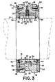
- Figure 3 is the section 3-3 of Figure 2.
- Figure 4 is an enlarged view of an oil feed tube as shown in Figure 2.
- Figure 5 is a view taken as indicated by the lines and arrows 5-5 which appear in Figure 2.
- Journal bearing 10 for carrying the radial load of a shaft 12 mounted for rotation therein in the direction indicated by the arrow 14 in Figure 2.
- Journal bearing 10 comprises five shoe assemblies 16 retained in position within an annular aligning ring 18.
- Aligning ring 18 is made of two split half sections which are secured together by means of joint screws 20 at two sets of mating faces and are properly positioned by a dowel 21.
- the shoe assemblies 16 are retained within a circular inner rim 22 of aligning ring 18 in circumferentially equally spaced relation as shown in the drawings.
- Each shoe assembly 16 comprises an arcuate shoe 24 provided with a bearing liner 25 on its inner surface, a shoe support 26 received in a recess hole centrally located in the outer surface of shoe 24, and a shoe support shim 28 located at the bottom of the recess hole containing the associated shoe support 26, the shims 28 being used for adjusting the position of the shoes 24 to allow for preloading of the bearing 10 as is conventional in the art.
- Bearing liner 25 provides a radially inwardly facing working face 30 of each shoe assembly 25 which face 30 is provided with the oil distributing means in accordance with the invention as will be described in detail hereafter with particular reference to Figure 5.
- each shoe assembly 16 is arranged to contact an insert 32 retained in aligning ring 18 in alignment with an associated shoe support 26.
- Each shoe support 26 and insert 32 have cooperating spherical surfaces to allow the shoe assemblies 16 to pivot freely in any direction to conform to the surface of shaft 12 as it rotates.
- shoe assemblies 16 are retained axially by a pair of shoe retaining plates 34 and 36 which have an annular configuration and are made of split halves.
- Each of the shoe retaining plates 34 and 36 is secured to a side of aligning ring 18 by means of plurality of circumferentially spaced screws 38 in the manner shown in Figures 2 and 3.
- Aligning ring 18 is located relative to retaining plates 34 and 36 by means of a pair of locating pins 35 and 37, respectively, as shown in Figures 2 and 3.
- Each of the shoes 24 is retained in position relative to the side plates 34 and 36 by means of a pair of shoe stop pins 40 and 42, respectively, which engage the shoe 24 from each side thereof as shown in Figure 3 and at a central location as is shown in Figure 2.
- a pin 43 is provided in aligning ring 18 for locating bearing 10 in its housing.
- journal bearing 10 is provided with means for distributing oil along the leading edge of each of the working faces 30 of each shoe assembly 16.
- an oil distributing groove 50 is formed in the working face 30 of each shoe assembly 16 and has a configuration and location as is best shown in Figure 5. As shown in this figure, oil distributing groove 50 is near the leading edge 51 of working face 30 and extends thereacross between its side edges 52 and 53. In effect, oil distributing groove 50 extends parallel to the axis of shaft 12 and across the path of movement of its surface. Oil distributing groove 50 has a leading edge 55 and a trailing edge 56. Trailing edge 56 is preferably chamfered so as to provide a chamfered surface 57 for the easy flow of oil from the oil distributing groove 50 in the trailing direction for covering the shoe working face 30 with oil during the rotation of shaft 12.
- oil distributing groove 50 comprises a deep central portion and a pair of relatively shallow end portions 58 and 59 which form bleed areas for the flow of oil to the areas of working face 30 near side edges 52 and 53. This direction of oil flow assures distribution of oil across the entire leading edge of the working face 30 so that no wearing face area is starved of oil and so as to maintain the oil flow to prevent any build up of hot oil.
- Each shoe assembly 16 has associated therewith an oil supply hole 60 extending radially through aligning ring 18 at a location aligned with the center of oil distributing groove 50, (see Figure 3).
- the outer end of each oil supply hole 60 communicates with a circumferentially extending oil inlet groove 62 which cooperates with the housing for journal bearing 10 to define an oil inlet conduit extending circumferentially around the exterior of aligning ring 18 for use in delivering oil supplied thereto into the outer end of each oil supply hole 60.
- Each shoe assembly 16 has an oil feed tube assembly 63 providing a radially extending passage 64 extending radially between the associated oil supply hole 60 and an opening formed by a socket 67 communicating with the center of oil distributing groove 50, as shown in the drawings.
- Each oil feed tube assembly 63 has ball-shaped portions 66 and 68 formed at the ends thereof and received in sockets 67 and 69 formed in shoe 24 and aligning ring 18, respectively.
- Ball-shaped portions 66 and 68 are provided with O-rings 70 and 72, respectively, constructed and arranged to contact the walls of sockets 67 and 69 in sealing engagement so that each oil feed tube assembly 63 is sealed against oil leakage.
- a shoulder 75 is formed in the opening of socket 67 for retaining portion 66 of the tube assembly 63 in engagement with shoe 24, and similarly, a shoulder 77 is formed at the opening to socket 69 for retaining the other end 68 of oil feed tube assembly 63 in engagement with aligning ring 18.
- Oil feed tube assembly 63 performs a dual function. Besides supplying oil from the oil supply hole 60 to the oil distribution groove 50 and preventing oil leakage from the tube assembly 63 because of the O-rings 70 and 72, the oil feed tube assembly 63 also assists in retaining the shoe 24 in position on the aligning ring 18. Also assisting in retaining the shoes 24 in ring 18 are the retainer pins 40 and 42 which extend from the shoe 24 into the retaining plates 34 and 36 as described above.
- Each of the retaining plates 34 and 36 is provided with four vertically extending discharge holes 84 and 86, ( Figure 3), respectively.
- the holes 84 and 86 serve to drain any oil accumulating at the lower portion of the journal bearing 10 through the retaining plates 34 and 36 to the bottom portion of the thrust bearing 10 from which the oil flows to a suitable oil collector for recirculation to the oil system, as is conventional in the art.
- the oil flow through the journal bearing 10 will now be described.
- the oil is supplied to the groove 62 on the exterior of aligning ring 18 and flows radially inwardly through the six oil supply holes 60 to the passage 64 of the associated oil feed tube assembly 63.
- the oil then flows from passage 64 into the center of oil distributing groove 50 and outwardly in each direction toward the bleed areas 58 and 59.
- shaft 12 rotates past the leading edge of each working surface 30, it draws oil from the oil distributing groove 50 along working surface 30 toward its trailing edge.
- some of the oil flows axially past the inner ends of retaining plates 34 and 36 which are provided with labyrinth seals 94 and 96 respectively.
- the oil flows axially along the shaft 12 where it is eventually collected for recirculation through the oil system as is conventional in the art.
- the oil moving through the journal bearing 10 is gravity fed back into a reservoir and then cooled and pumped back out into the bearing 10 for reuse.
Landscapes
- Engineering & Computer Science (AREA)
- General Engineering & Computer Science (AREA)
- Mechanical Engineering (AREA)
- Chemical & Material Sciences (AREA)
- Oil, Petroleum & Natural Gas (AREA)
- Physics & Mathematics (AREA)
- Fluid Mechanics (AREA)
- Sliding-Contact Bearings (AREA)
- Support Of The Bearing (AREA)
- Sealing Devices (AREA)
Description
- This invention relates to journal bearings for supporting a rotating shaft, comprising an aligning ring, a plurality of shoe assemblies retained within said aligning ring, each shoe assembly including an arcuate shoe having a working face for bearing contact with the rotating shaft, and means for delivering oil to the leading edge area of said working face of each shoe including an oil distribution groove formed in said working face near the leading edge of said shoe and extending across said shoe and passage means for delivering oil to said oil distribution groove.
- Such a journal bearing is known from the FR-A-1 506 849. The oil distribution groove of this journal bearing is an axial aperture having the same depth all over its entire length. This aperture leads the oil to the outside of the shoe thus consuming a large quantity of oil to prevent the wearing face areas from being starved of oil.
- The passage means of this journal bearing include an opening in the shoe communicating with the central portion of the oil distribution groove and an oil supply hole extending radially through the aligning ring. An oil feed tube is connected between the oil supply hole and the opening in the shoe for providing flow communication therebetween.
- Accordingly, it has been desired to reduce the amount of oil flow in a journal bearing lubrication system, to increase the load carrying capabilities, and to lower the power loss, in the interest of energy conservation. Besides reducing the amount of oil used, and lowering the power loss, such a system would desirably use a smaller pump and other auxiliary equipment and be more efficient.
- Therefore it is the object of the invention to provide a journal bearing of the generic kind which increases the load carrying capacity, uses less oil, consumes less power, uses smaller auxiliary equipment, and is very efficient.
- This object is accomplished in that the oil distribution groove comprises a deep central portion and relatively shallow end portions extending to the side edges of said working face for forming bleed areas for the flow of oil from said deep central portion.
- The shoe journal bearing of the present invention assures distribution of oil across the entire leading edge of the working face so that no wearing face area is starved of oil and so as to maintain the oil flow to prevent any build up of hot oil, conserves energy by reducing the oil flow and consumes less power. It uses less lubricant, thus requiring a smaller pump and other auxiliary equipment. The journal bearing is efficient, it applies the oil lubricant where it is needed and used, at the working face of the shoe, and does not flood the cavity between the shoe retaining rings.
- The journal bearing runs cooler since the oil is applied just where it is used, and since it runs cooler, it can carry higher loads.
- Advantageously the oil distribution groove has a chamfered trailing edge for providing a chamfered surface to ease the flow of oil from the oil distribution groove in the trailing direction.
- If with the journal bearing according to the invention said passage means includes an opening in said shoe communicating with the central portion of said oil distribution groove, an oil supply hole extending radially through said aligning ring and in alignment with said opening in said shoe, and an oil feed tube connected between the oil supply hole and said opening in said shoe for providing flow communication therebetween, the said oil feed tube may have ball-shaped portions at the ends therefore receiving O-ring seals, said O-ring seals cooperating with said aligning ring and said shoe to provide sealing contact therewith.
- Said ball-shaped portions of said oil feed tube may be received in sockets in said aligning ring and said shoe and cooperate therewith to seal the tube against oil leaks, and shoulders may be formed at the openings to said sockets for retaining the ends of said tube therein.
- By means of drawings an embodiment of the invention is further explained.
- Figure 1 is a front elevation-view of a journal bearing positioned on a rotating shaft.
- Figure 2 is a side view of the journal bearing shown in Figure 1.
- Figure 3 is the section 3-3 of Figure 2.
- Figure 4 is an enlarged view of an oil feed tube as shown in Figure 2.
- Figure 5 is a view taken as indicated by the lines and arrows 5-5 which appear in Figure 2.
- Referring to the drawings, there is shown a shoe journal bearing 10 for carrying the radial load of a
shaft 12 mounted for rotation therein in the direction indicated by thearrow 14 in Figure 2. Journal bearing 10 comprises fiveshoe assemblies 16 retained in position within anannular aligning ring 18. -
Aligning ring 18 is made of two split half sections which are secured together by means ofjoint screws 20 at two sets of mating faces and are properly positioned by adowel 21. Theshoe assemblies 16 are retained within a circularinner rim 22 of aligningring 18 in circumferentially equally spaced relation as shown in the drawings. - Each
shoe assembly 16 comprises anarcuate shoe 24 provided with abearing liner 25 on its inner surface, ashoe support 26 received in a recess hole centrally located in the outer surface ofshoe 24, and ashoe support shim 28 located at the bottom of the recess hole containing the associatedshoe support 26, theshims 28 being used for adjusting the position of theshoes 24 to allow for preloading of thebearing 10 as is conventional in the art.Bearing liner 25 provides a radially inwardly facing workingface 30 of eachshoe assembly 25 whichface 30 is provided with the oil distributing means in accordance with the invention as will be described in detail hereafter with particular reference to Figure 5. - The
shoe support 26 of eachshoe assembly 16 is arranged to contact aninsert 32 retained in aligningring 18 in alignment with an associatedshoe support 26. Each shoe support 26 andinsert 32 have cooperating spherical surfaces to allow the shoe assemblies 16 to pivot freely in any direction to conform to the surface ofshaft 12 as it rotates. - As is shown in the drawings,
shoe assemblies 16 are retained axially by a pair ofshoe retaining plates shoe retaining plates ring 18 by means of plurality of circumferentially spacedscrews 38 in the manner shown in Figures 2 and 3.Aligning ring 18 is located relative to retainingplates pins shoes 24 is retained in position relative to theside plates shoe stop pins shoe 24 from each side thereof as shown in Figure 3 and at a central location as is shown in Figure 2. Apin 43 is provided in aligningring 18 for locating bearing 10 in its housing. - In accordance with the invention, journal bearing 10 is provided with means for distributing oil along the leading edge of each of the working faces 30 of each
shoe assembly 16. To this end, anoil distributing groove 50 is formed in the workingface 30 of eachshoe assembly 16 and has a configuration and location as is best shown in Figure 5. As shown in this figure,oil distributing groove 50 is near the leadingedge 51 of workingface 30 and extends thereacross between itsside edges oil distributing groove 50 extends parallel to the axis ofshaft 12 and across the path of movement of its surface.Oil distributing groove 50 has a leadingedge 55 and atrailing edge 56.Trailing edge 56 is preferably chamfered so as to provide achamfered surface 57 for the easy flow of oil from theoil distributing groove 50 in the trailing direction for covering theshoe working face 30 with oil during the rotation ofshaft 12. - Referring to Figures 3 and 5,
oil distributing groove 50 comprises a deep central portion and a pair of relativelyshallow end portions face 30near side edges face 30 so that no wearing face area is starved of oil and so as to maintain the oil flow to prevent any build up of hot oil. - Each
shoe assembly 16 has associated therewith anoil supply hole 60 extending radially through aligningring 18 at a location aligned with the center ofoil distributing groove 50, (see Figure 3). The outer end of eachoil supply hole 60 communicates with a circumferentially extendingoil inlet groove 62 which cooperates with the housing for journal bearing 10 to define an oil inlet conduit extending circumferentially around the exterior of aligningring 18 for use in delivering oil supplied thereto into the outer end of eachoil supply hole 60. - Each
shoe assembly 16 has an oil feed tube assembly 63 providing a radially extendingpassage 64 extending radially between the associatedoil supply hole 60 and an opening formed by asocket 67 communicating with the center ofoil distributing groove 50, as shown in the drawings. Each oil feed tube assembly 63 has ball-shaped portions sockets shoe 24 and aligningring 18, respectively. Ball-shaped portions rings 70 and 72, respectively, constructed and arranged to contact the walls ofsockets - A shoulder 75 is formed in the opening of
socket 67 for retainingportion 66 of the tube assembly 63 in engagement withshoe 24, and similarly, a shoulder 77 is formed at the opening tosocket 69 for retaining theother end 68 of oil feed tube assembly 63 in engagement with aligningring 18. - Oil feed tube assembly 63 performs a dual function. Besides supplying oil from the
oil supply hole 60 to theoil distribution groove 50 and preventing oil leakage from the tube assembly 63 because of the O-rings 70 and 72, the oil feed tube assembly 63 also assists in retaining theshoe 24 in position on the aligningring 18. Also assisting in retaining theshoes 24 inring 18 are theretainer pins shoe 24 into theretaining plates - Each of the
retaining plates discharge holes holes retaining plates - The oil flow through the journal bearing 10 will now be described. The oil is supplied to the
groove 62 on the exterior of aligningring 18 and flows radially inwardly through the sixoil supply holes 60 to thepassage 64 of the associated oil feed tube assembly 63. The oil then flows frompassage 64 into the center ofoil distributing groove 50 and outwardly in each direction toward thebleed areas shaft 12 rotates past the leading edge of each workingsurface 30, it draws oil from theoil distributing groove 50 along workingsurface 30 toward its trailing edge. In addition, some of the oil flows axially past the inner ends ofretaining plates labyrinth seals shaft 12 where it is eventually collected for recirculation through the oil system as is conventional in the art. Typically, the oil moving through the journal bearing 10 is gravity fed back into a reservoir and then cooled and pumped back out into thebearing 10 for reuse.
Claims (4)
- A journal bearing (10) for supporting a rotating shaft (12), comprising
an aligning ring (18),
a plurality of shoe assemblies (16) retained within said aligning ring (18),
each shoe assembly (16) including an arcuate shoe (24) having a working face (30) for bearing contact with the rotating shaft (12), and
means for delivering oil to the leading edge area of said working face (30) of each shoe (24) including
an oil distribution groove (50) formed in said working face (30) near the leading edge (51) of said shoe (24) and extending across said shoe (24), and
passage means (62, 60, 64) for delivering oil to said oil distribution groove (50), characterized in that
said oil distribution groove (50) comprises a deep central portion and relatively shallow end portions (58, 59) extending to the side edges (52, 53) of said working face (30) for forming bleed areas for the flow of oil from said deep central portion. - A journal bearing according to claim 1, wherein the oil distribution groove (50) includes a chamfered trailing edge (56).
- A journal bearing according to Claim 1 or 2 wherein
said passage means includes an opening (67) in said shoe (24) communicating with the central portion of said oil distribution groove (50),
an oil supply hole (60) extending radially through said aligning ring (18) and in alignment with said opening (67) in said shoe (24), and
an oil feed tube (63) connected between the oil supply hole (60) and said opening (67) in said shoe (24) for providing flow communication therebetween,
characterized in that
said oil feed tube (63) has ball-shaped portions (66, 68) at the ends thereof receiving O-ring seals (70, 72),
said O-ring seals (70, 72) cooperating with said aligning ring (18) and said shoe (24) to provide sealing contact therewith. - A journal bearing according to Claim 3 wherein
said ball-shaped portions (66, 68) of said oil feed tube (63) are received in sockets (67, 69) in said aligning ring (18) and said shoe (24) and cooperate therewith to seal the tube (63) against oil leaks, and
including shoulders (75, 77) formed at the openings to said sockets (67, 69) for retaining the ends of said tube (63) therein.
Applications Claiming Priority (3)
| Application Number | Priority Date | Filing Date | Title |
|---|---|---|---|
| US06/646,163 US4568204A (en) | 1984-09-04 | 1984-09-04 | Journal bearing |
| US646163 | 1984-09-04 | ||
| EP85102262A EP0173792B1 (en) | 1984-09-04 | 1985-02-28 | Journal bearing |
Related Parent Applications (2)
| Application Number | Title | Priority Date | Filing Date |
|---|---|---|---|
| EP85102262.4 Division | 1985-02-28 | ||
| EP85102262A Division EP0173792B1 (en) | 1984-09-04 | 1985-02-28 | Journal bearing |
Publications (3)
| Publication Number | Publication Date |
|---|---|
| EP0361544A2 EP0361544A2 (en) | 1990-04-04 |
| EP0361544A3 EP0361544A3 (en) | 1992-01-29 |
| EP0361544B1 true EP0361544B1 (en) | 1994-06-01 |
Family
ID=24592022
Family Applications (2)
| Application Number | Title | Priority Date | Filing Date |
|---|---|---|---|
| EP89121544A Expired - Lifetime EP0361544B1 (en) | 1984-09-04 | 1985-02-28 | Journal bearing |
| EP85102262A Expired EP0173792B1 (en) | 1984-09-04 | 1985-02-28 | Journal bearing |
Family Applications After (1)
| Application Number | Title | Priority Date | Filing Date |
|---|---|---|---|
| EP85102262A Expired EP0173792B1 (en) | 1984-09-04 | 1985-02-28 | Journal bearing |
Country Status (5)
| Country | Link |
|---|---|
| US (1) | US4568204A (en) |
| EP (2) | EP0361544B1 (en) |
| JP (1) | JPS6165904A (en) |
| CA (1) | CA1254253A (en) |
| DE (2) | DE3581018D1 (en) |
Families Citing this family (34)
| Publication number | Priority date | Publication date | Assignee | Title |
|---|---|---|---|---|
| DE3617289A1 (en) * | 1986-05-23 | 1987-11-26 | Braunschweiger Huettenwerk | HYDRODYNAMIC RADIAL SLIDING BEARING |
| US4886430A (en) * | 1988-07-18 | 1989-12-12 | Westinghouse Electric Corp. | Canned pump having a high inertia flywheel |
| DE3834471A1 (en) * | 1988-10-11 | 1990-04-12 | Gutehoffnungshuette Man | FASTENING A SOCKET IN A HUB FOR A COMPONENT WITH A ROTATING LOAD |
| US4913563A (en) * | 1988-11-07 | 1990-04-03 | Westinghouse Electric Corp. | Hydrodynamic pivoted pad bearing assembly for a reactor coolant pump |
| US5288153A (en) * | 1993-01-04 | 1994-02-22 | Delaware Capital Formation, Inc. | Tilting pad journal bearing using directed lubrication |
| JPH0710861U (en) * | 1993-06-30 | 1995-02-14 | 株式会社三協精機製作所 | Motor rotor removal prevention structure |
| US5795076A (en) * | 1995-10-13 | 1998-08-18 | Orion Corporation | Tilt pad hydrodynamic bearing for rotating machinery |
| US5879085A (en) * | 1995-10-13 | 1999-03-09 | Orion Corporation | Tilt pad hydrodynamic bearing for rotating machinery |
| US5951172A (en) * | 1995-10-13 | 1999-09-14 | Orion Corporation | Sleeve bearing lubrication |
| US5720558A (en) * | 1995-10-16 | 1998-02-24 | Dresser-Rand Company | Tilting bearing pad with an axial feed groove having an exit side profiled area |
| US5702186A (en) * | 1996-08-02 | 1997-12-30 | Westinghouse Electric Corporation | Journal bearing with leading edge groove vent |
| US6499883B2 (en) * | 1997-03-31 | 2002-12-31 | Whm Holding Corporation | Tilting pad for bearings |
| WO2001081781A1 (en) * | 1998-07-30 | 2001-11-01 | Westinghouse Electric Corporation | Journal bearing with oil supply groove vented in a path perpendicular to the leading edge of a bearing shoe |
| US6739756B2 (en) * | 2001-03-12 | 2004-05-25 | Whm Holding Corporation | Combination thrust bearing and journal bearing, and method for distributing fluid to same |
| GB0115336D0 (en) * | 2001-06-22 | 2001-08-15 | Federal Mogul Rpb Ltd | Bearing |
| RU2315211C2 (en) * | 2003-06-07 | 2008-01-20 | Сименс Акциенгезелльшафт | Segment type bearing assembly |
| US7758247B2 (en) * | 2005-02-28 | 2010-07-20 | Kingsbury, Inc. | Journal bearing having surface-contact retained shoes |
| US7237957B2 (en) * | 2005-02-28 | 2007-07-03 | Kingsbury, Inc. | Journal bearing having self-retaining shoes and method of using the same to support a rotating shaft |
| GB2424043A (en) * | 2005-03-12 | 2006-09-13 | Siemens Ind Turbomachinery Ltd | A tilting pad bearing assembly |
| EP1890045A1 (en) * | 2006-08-16 | 2008-02-20 | Siemens Aktiengesellschaft | hydrodynamic journal bearings for large turbo sets |
| US8308366B2 (en) * | 2009-06-18 | 2012-11-13 | Eaton Industrial Corporation | Self-aligning journal bearing |
| IT1395717B1 (en) * | 2009-09-22 | 2012-10-19 | Nuovo Pignone Spa | BEARING, OIL AND METHOD DISTRIBUTION MECHANISM. |
| IT1395716B1 (en) * | 2009-09-22 | 2012-10-19 | Nuovo Pignone Spa | BEARING, FIXING MECHANISM AND METHOD TO FIX AT LEAST ONE SHOE. |
| EP2669537A1 (en) * | 2012-06-01 | 2013-12-04 | Alstom Technology Ltd. | Journal pad bearing for turbine |
| JP2015007463A (en) | 2013-06-26 | 2015-01-15 | 三菱日立パワーシステムズ株式会社 | Tilting pad bearing |
| US9618048B2 (en) | 2014-08-12 | 2017-04-11 | Lufkin Industries, Llc | Reverse bypass cooling for tilted pad journal and tilting pad thrust bearings |
| CN105805155A (en) * | 2014-12-31 | 2016-07-27 | 锦州新锦化机械制造有限公司 | Cooled bearing |
| JP5922809B1 (en) * | 2015-01-30 | 2016-05-24 | 三菱日立パワーシステムズ株式会社 | Tilting pad bearing and rotating machine |
| US10161443B2 (en) * | 2015-01-30 | 2018-12-25 | Siemens Aktiengesellschaft | Bearing shoe for supporting a rotor journal in a turbine engine |
| US9771972B2 (en) | 2015-07-01 | 2017-09-26 | Elliott Company | Self-leveling thrust bearing retainer |
| US9587672B1 (en) | 2015-08-11 | 2017-03-07 | Lufkin Industries, Llc | Adjustable offset pivot journal pad |
| CN105370730B (en) * | 2015-12-18 | 2018-11-13 | 中车集团台州第七八一六工厂 | A kind of tilting-pad bearing for rotor |
| DE112019007871T5 (en) * | 2019-11-05 | 2022-09-01 | Mitsubishi Electric Corporation | PLAIN BEARINGS AND ROTARY MACHINE |
| CN113565862A (en) * | 2021-06-18 | 2021-10-29 | 湖南崇德科技股份有限公司 | Radial bearing with adjustable fulcrum of tilting pad |
Family Cites Families (10)
| Publication number | Priority date | Publication date | Assignee | Title |
|---|---|---|---|---|
| US2348928A (en) * | 1941-11-13 | 1944-05-16 | Heald Machine Co | Bearing construction |
| US3023055A (en) * | 1960-03-14 | 1962-02-27 | Earl A Thompson | Pressure fed rocker shoe bearing |
| FR1514912A (en) * | 1963-01-19 | 1968-03-01 | Rateau Soc | Advanced multi-pad gas bearings |
| CH430344A (en) * | 1965-12-31 | 1967-02-15 | Bbc Brown Boveri & Cie | Radial plain bearings |
| JPS5516185U (en) * | 1978-07-20 | 1980-02-01 | ||
| JPS55135225A (en) * | 1979-04-06 | 1980-10-21 | Hitachi Ltd | Tilting pad journal bearing |
| JPS5715117A (en) * | 1980-07-03 | 1982-01-26 | Mitsubishi Heavy Ind Ltd | Journal bearing |
| JPS57107428A (en) * | 1980-12-23 | 1982-07-03 | Toshiba Corp | Pad journal bearing |
| AU554805B2 (en) * | 1982-06-02 | 1986-09-04 | Ifield Engineering Pty. Ltd. | Hydrostatic bearing |
| US4490054A (en) * | 1983-03-21 | 1984-12-25 | Cincinnati Milacron Inc. | Machine tool bearing system |
-
1984
- 1984-09-04 US US06/646,163 patent/US4568204A/en not_active Expired - Lifetime
-
1985
- 1985-02-19 JP JP60031392A patent/JPS6165904A/en active Granted
- 1985-02-28 DE DE8585102262T patent/DE3581018D1/en not_active Expired - Fee Related
- 1985-02-28 EP EP89121544A patent/EP0361544B1/en not_active Expired - Lifetime
- 1985-02-28 EP EP85102262A patent/EP0173792B1/en not_active Expired
- 1985-02-28 DE DE3587837T patent/DE3587837T2/en not_active Expired - Fee Related
- 1985-04-09 CA CA000478549A patent/CA1254253A/en not_active Expired
Also Published As
| Publication number | Publication date |
|---|---|
| EP0361544A3 (en) | 1992-01-29 |
| EP0173792B1 (en) | 1991-01-02 |
| DE3587837T2 (en) | 1994-11-03 |
| JPH0536646B2 (en) | 1993-05-31 |
| DE3581018D1 (en) | 1991-02-07 |
| EP0361544A2 (en) | 1990-04-04 |
| JPS6165904A (en) | 1986-04-04 |
| US4568204A (en) | 1986-02-04 |
| CA1254253A (en) | 1989-05-16 |
| EP0173792A3 (en) | 1987-07-15 |
| DE3587837D1 (en) | 1994-07-07 |
| EP0173792A2 (en) | 1986-03-12 |
Similar Documents
| Publication | Publication Date | Title |
|---|---|---|
| EP0361544B1 (en) | Journal bearing | |
| EP0163815B1 (en) | Thrust bearing | |
| EP1543250B1 (en) | Integrated oil transfer sleeve and bearing | |
| US5271676A (en) | Combination package tilt pad journal bearing/dual self equalizing thrust bearings, with hydrostatic lift provisions | |
| EP3412915B1 (en) | Self-adjusting drum system | |
| US5409350A (en) | Water pump bearing and seal cartridge | |
| US6361215B1 (en) | Journal bearing | |
| JPS63231021A (en) | Lubricating device for roller bearing | |
| US4421425A (en) | Fixed fad thrust bearing | |
| US4863291A (en) | Bearing assembly | |
| US2862455A (en) | Hydrodynamic machine | |
| US6170832B1 (en) | Fluid ring seal system and method | |
| EP1390631B1 (en) | Package bearing with lubrication ports | |
| CN103206455B (en) | Motor front bearing and centrifugal compressor and refrigeration equipment comprising same | |
| US7055826B2 (en) | Seal and bearing assembly | |
| EP0207746B1 (en) | Improvements in or relating to swivel or rotating joints | |
| CN103206398B (en) | Motor rear bearing, centrifugal compressor comprising same and refrigeration equipment | |
| EP0221727B1 (en) | Bearing assembly | |
| US4765760A (en) | Bearing assembly | |
| EP0329193A1 (en) | An improved bearing assembly, such as a thrust bearing | |
| JP2003148390A (en) | Double suction turbine pump | |
| CN219605851U (en) | Self-lubricating bearing end cover, bearing assembly and high-frequency breaking hammer | |
| JPS59103021A (en) | Static pressure type fluid bearing | |
| CA1291193C (en) | Bearing assembly | |
| CN116336083A (en) | High-speed bearing with outer ring roller path provided with small lubrication holes and direct trace grease supply lubrication system |
Legal Events
| Date | Code | Title | Description |
|---|---|---|---|
| PUAI | Public reference made under article 153(3) epc to a published international application that has entered the european phase |
Free format text: ORIGINAL CODE: 0009012 |
|
| 17P | Request for examination filed |
Effective date: 19891121 |
|
| AC | Divisional application: reference to earlier application |
Ref document number: 173792 Country of ref document: EP |
|
| AK | Designated contracting states |
Kind code of ref document: A2 Designated state(s): DE FR GB IT |
|
| PUAL | Search report despatched |
Free format text: ORIGINAL CODE: 0009013 |
|
| AK | Designated contracting states |
Kind code of ref document: A3 Designated state(s): DE FR GB IT |
|
| 17Q | First examination report despatched |
Effective date: 19930715 |
|
| GRAA | (expected) grant |
Free format text: ORIGINAL CODE: 0009210 |
|
| AC | Divisional application: reference to earlier application |
Ref document number: 173792 Country of ref document: EP |
|
| AK | Designated contracting states |
Kind code of ref document: B1 Designated state(s): DE FR GB IT |
|
| REF | Corresponds to: |
Ref document number: 3587837 Country of ref document: DE Date of ref document: 19940707 |
|
| ET | Fr: translation filed | ||
| ITF | It: translation for a ep patent filed | ||
| PLBE | No opposition filed within time limit |
Free format text: ORIGINAL CODE: 0009261 |
|
| STAA | Information on the status of an ep patent application or granted ep patent |
Free format text: STATUS: NO OPPOSITION FILED WITHIN TIME LIMIT |
|
| 26N | No opposition filed | ||
| REG | Reference to a national code |
Ref country code: GB Ref legal event code: IF02 |
|
| PGFP | Annual fee paid to national office [announced via postgrant information from national office to epo] |
Ref country code: DE Payment date: 20020425 Year of fee payment: 18 |
|
| PGFP | Annual fee paid to national office [announced via postgrant information from national office to epo] |
Ref country code: FR Payment date: 20030220 Year of fee payment: 19 |
|
| PGFP | Annual fee paid to national office [announced via postgrant information from national office to epo] |
Ref country code: GB Payment date: 20030224 Year of fee payment: 19 |
|
| PG25 | Lapsed in a contracting state [announced via postgrant information from national office to epo] |
Ref country code: DE Free format text: LAPSE BECAUSE OF NON-PAYMENT OF DUE FEES Effective date: 20030902 |
|
| PG25 | Lapsed in a contracting state [announced via postgrant information from national office to epo] |
Ref country code: GB Free format text: LAPSE BECAUSE OF NON-PAYMENT OF DUE FEES Effective date: 20040228 |
|
| GBPC | Gb: european patent ceased through non-payment of renewal fee | ||
| PG25 | Lapsed in a contracting state [announced via postgrant information from national office to epo] |
Ref country code: FR Free format text: LAPSE BECAUSE OF NON-PAYMENT OF DUE FEES Effective date: 20041029 |
|
| REG | Reference to a national code |
Ref country code: FR Ref legal event code: ST |