EP0163134A2 - Method and apparatus for controlling air-fuel ratio in internal combustion engine - Google Patents
Method and apparatus for controlling air-fuel ratio in internal combustion engine Download PDFInfo
- Publication number
- EP0163134A2 EP0163134A2 EP85105059A EP85105059A EP0163134A2 EP 0163134 A2 EP0163134 A2 EP 0163134A2 EP 85105059 A EP85105059 A EP 85105059A EP 85105059 A EP85105059 A EP 85105059A EP 0163134 A2 EP0163134 A2 EP 0163134A2
- Authority
- EP
- European Patent Office
- Prior art keywords
- fuel ratio
- air
- engine
- temperature
- limit value
- Prior art date
- Legal status (The legal status is an assumption and is not a legal conclusion. Google has not performed a legal analysis and makes no representation as to the accuracy of the status listed.)
- Granted
Links
Images


Classifications
-
- F—MECHANICAL ENGINEERING; LIGHTING; HEATING; WEAPONS; BLASTING
- F02—COMBUSTION ENGINES; HOT-GAS OR COMBUSTION-PRODUCT ENGINE PLANTS
- F02D—CONTROLLING COMBUSTION ENGINES
- F02D41/00—Electrical control of supply of combustible mixture or its constituents
- F02D41/02—Circuit arrangements for generating control signals
- F02D41/14—Introducing closed-loop corrections
- F02D41/1438—Introducing closed-loop corrections using means for determining characteristics of the combustion gases; Sensors therefor
- F02D41/1486—Introducing closed-loop corrections using means for determining characteristics of the combustion gases; Sensors therefor with correction for particular operating conditions
-
- F—MECHANICAL ENGINEERING; LIGHTING; HEATING; WEAPONS; BLASTING
- F02—COMBUSTION ENGINES; HOT-GAS OR COMBUSTION-PRODUCT ENGINE PLANTS
- F02D—CONTROLLING COMBUSTION ENGINES
- F02D41/00—Electrical control of supply of combustible mixture or its constituents
- F02D41/02—Circuit arrangements for generating control signals
- F02D41/04—Introducing corrections for particular operating conditions
- F02D41/06—Introducing corrections for particular operating conditions for engine starting or warming up
Definitions
- the present invention relates to a method and apparatus for feedback control of the air-fuel ratio in an internal combustion engine.
- a lean burn system As measures taken against exhaust gas pollution and fuel consumption, a lean burn system has recently been developed. According to this lean burn system, a lean mixture sensor is provided for generating an analog current in proportion to the air-fuel mixture on the lean side in an exhaust pipe of an engine. Thus, the feedback of the air-fuel ratio of the - engine can be controlled by using the analog output of the lean mixture sensor, thereby attaining an arbitrary air-fuel ratio on the lean side.
- a lean burn system can be forcibly applied to the warming-up mode engine in the same way as to the after-warming-up mode engine.
- the temperature of the engine is too low, vaporization of fuel within chambers of the engine is poor, so that the combustion of fuel is insufficient, inviting misfires and thus reducing drivability.
- the aimed air-fuel ratio is variable in accordance with the engine temperature.
- the aimed air-fuel ratio can be on the lean side with respect to the stoichimetric air-fuel ratio.
- the aimed air-fuel ratio can be rich, however, on the lean side with respect to the stoichimetric air-fuel ratio.
- reference numeral 1 designates a four-cycle spark ignition engine disposed in an automotive vehicle.
- a surge tank 3 in which a pressure sensor 4 is provided.
- the pressure sensor 4 is used for detecting the absolute pressure within the intake-air passage 2 and transmits its output signal to a multiplexer-incorporating analog-to-digital (A/D) converter 101 of a control circuit 10.
- A/D analog-to-digital
- crank angle sensors 6 and 7 Disposed in a distributor 5 are crank angle sensors 6 and 7 for detecting the angle of the crankshaft (not shown) of the engine 1.
- the crank-angle sensor 6 generates a pulse signal at every 720° crank angle (CA) while the crank-angle sensor 7 generates a pulse signal at every 30°CA.
- the pulse signals of the crank angle sensors 6 and 7 are supplied to an input/ output (I/O) interface 103 of the control circuit 10.
- the pulse signal of the crank angle sensor 7 is then supplied to an interruption terminal of a central processing unit (CPU) 105.
- CPU central processing unit
- a fuel injector 8 for supplying pressurized fuel from the fuel system (not shown) to the air-intake port of the cylinder of the engine 1.
- other fuel injectors are also provided for other cylinders, though not shown in Fig. 1.
- a coolant temperature sensor 11 Disposed in a cylinder block 9 of the engine 1 is a coolant temperature sensor 11 for detecting the temperature of the coolant.
- the coolant temperature sensor 11 generates an analog voltage signal in response to the temperature of the coolant and transmits it to the A/D converter 101 of the control circuit 10.
- a lean mixture sensor 13 for detecting the concentration of oxygen composition in the exhaust gas.
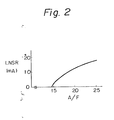
- the lean mixture sensor 13 generates a current signal LNSR as shown in Fig. 2 and transmits it via a current-to-voltage converter circuit 102 of the control circuit 10 to the A/D converter 101 thereof.
- the control circuit 10 which may be constructed by a microcomputer, includes a driver circuit 104 for driving the fuel injector 8, a timer counter 106, a read-only memory (ROM) 107 for storing a main routine, interrupt routines such as a fuel injection routine, an ignition timing routine, tables (maps), constants, etc., a random access memory 108 (RAM) for storing temporary data, a clock generator 109 for generating various clock signals, and the like, in addition to the A/D converter 101, the current-to-voltage converter circuit 102, the I/O interface 103, and the CPU 105.
- ROM read-only memory
- RAM random access memory
- clock generator 109 for generating various clock signals, and the like, in addition to the A/D converter 101, the current-to-voltage converter circuit 102, the I/O interface 103, and the CPU 105.
- the timer counter 106 may include a free-run counter, a compare register, a comparator for comparing the content of the free-run counter with that of-the compare register, flag registers for compare interruption, injection control, and the like.
- the timer counter l06 also may include a plurality of compare registers and a plurality of comparators. In this case, the timer counter 106 is used for controlling the injection start and end operation.
- Interruptions occur at the CPU 105, when the A/D converter 101 completes an A/D conversion and generates an interrupt signal; when the crank angle sensor 7 generates a pulse signal; when the timer counter 106 generates a compare interrupt signal; and when the clock generator 109 generates a special clock signal.
- the pressure data PM of the pressure sensor 4, the coolant temperature data THW, and the current data LNSR of the lean mixture sensor 13 are fetched by an A/D conversion routine(s) executed at every predetermined time period and are then stored in the RAM 108. That is, the data PM, THW, and LNSR in the RAM 108 are renewed at every predetermined time period.
- the engine rotational speed Ne is calculated by an interrupt routine executed at 30°CA, i.e., at every pulse signal of the crank angle sensor 7, and is then stored in the RAM 108.
- control circuit 10 of Fig. 1 The operation of the control circuit 10 of Fig. 1 will be explained with reference to the flow charts of Figs. 3, 6, and 9 through 12.
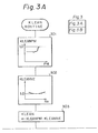
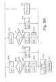
- Figure 3 is a routine for calculating a lean air-fuel ratio correction coefficient KLEAN executed at every predetermined time period. Note that the coefficient KLEAN satisfies the condition: KLEAN ⁇ 1.0.
- KLEANPM is calculated from a one-dimensional map stored in the ROM 107 by using the parameter PM as shown in the block of step 301.
- KLEANNE is calculated from a one-dimensional map stored in the ROM 107 by using the parameter Ne as shown on the block of step 302. Then at step 303, KLEAN ⁇ KLEANPM ⁇ KLEANNE.
- step 304 it is determined whether or not the coolant temperature THW stored in the RAM 108 is lower than a predetermined temperature T 1 , which is, for example, 55°C, while at step 307, it is determined whether or not the coolant temperature THW is higher than a predetermined temperature T 2 , which is, for example, 80°C. That is, the temperature T 2 is higher than the temperature T 1 . Note that a warming-up operation is usually completed, when the coolant temperature THW reaches the temperature T 2 .
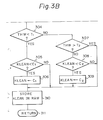
- step 305 the lean air-fuel ratio correction coefficient KLEAN is guarded by a lower limit value C 1 which is relatively large and is, for example, 1.0. That is, at step 305, it id determined whether or not the coefficient KLEAN is smaller then the lower limit value Cl . If KLEAN ⁇ C, , then at step 306, KLEAN ⁇ C l . Otherwise, the control proceeds directly to step 310.
- the control proceeds to steps 308 and 309 in which the lean air-fuel ratio correction coefficient KLEAN is guarded by a lower limit value C 2 .
- the lower limit value C2 is smaller than the lower limit value C 1 , and is, for example, 0.6 to 0.8. That is, at step 308, it is determined whether or not the coefficient KLEAN is smaller than the lower limit value C 2 . If KLEAN ⁇ C 2 , then at step 309, KLEAN ⁇ C 2 . Otherwise, the control proceeds directly to step 310.
- step 310 the control proceeds directly to step 310. That is, in this case, since it is considered that a warming-up operation is completed, no limitation is applied to the lean air-fuel correction coefficient KLEAN.
- the finally obtained lean air-fuel ratio correction coefficient KLEAN is stored in the RAM 108 at step 310.
- the routine of Fig. 3 is completed by step 311.
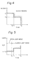
- the lean air-fuel ratio correction coefficient KLEAN calculated by the routine of Fig. 3 will be explained with reference to Fig. 4. As shown in Fig. 4, if THW ⁇ T 1 , the coefficient KLEAN is controlled to be larger than the limit value C 1 . If T 1 ⁇ THW ⁇ T 2 , the coefficient KLEAN is controlled to be larger than the limit value C 2 . If THW > T 2 , no limitation is applied to the coefficient KLEAN derived by the parameters PM and Ne. Thus, the lower limit value of the lean air-fuel ratio correction coefficient KLEAN is controlled by the coolant temperature THW.
- the coefficient KLEAN is guarded by a large lower limit value, i.e., the value C 1 .
- the controlled air-fuel ratio is determined by the coefficient KLEAN. Therefore, the air-fuel ratio is controlled in accordance with the coolant temperature THW. As a result, when the coolant temperature THW is low, the controlled lean air-fuel ratio becomes richer.
- a value TO of the coolant temperature THW is, for example, 50°C.
- the condition THW ⁇ T 0 is one of the feedback control conditions, which will be later explained. That is, if THW > T and the other feedback control conditions are satisfied, feedback control (closed-loop control) of the air-fuel ratio is carried out, while, if THW ⁇ T 0 , open-loop control of the air-fuel ratio is carried out.
- Figure 5 shows the lower limit characteristics of the controlled air-fuel ratio in the case where control of the air-fuel ratio is carried out by using the lean air-fuel ratio correction coefficient KLEAN obtained by the routine of Fig. 3.
- the lower limit of the controlled air-fuel ratio is dependent upon the coolant temperature THW. That is, even during a warming-up mode (T 1 ⁇ THW ⁇ T 2 ), fuel combustion is carried out at a lean air-fuel ratio. Further, during a warming-up mode where the coolant temperature THW is too low (T 0 ⁇ THW ⁇ T l ), fuel combustion may be carried out at a lean air-fuel ratio. Thus, the fuel consumption efficiency during a warming-up mode is improved without reducing the combustion state.
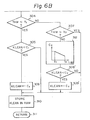
- step 312 is added to the routine of Fig. 3, and steps 308' and 309' are provided instead of steps 308 and 309 of Fig. 3.
- steps 312, 308' and 309' are carried out. That is, at step 312, a lower limit value C is calculated from a one-dimensional v map stored in the ROM 107 by using the parameter THW as shown in the block of step 312.
- the lean air-fuel ratio correction coefficient KLEAN is guarded by the lower limit value C v .
- step 308' it is determined whether or not the coefficient KLEAN is smaller than the lower limit value C v . If KLEAN ⁇ C v , then at step 309', KLEAN ⁇ C. Otherwise, the control proceeds directly to step 310. Thus, if T 1 ⁇ THW ⁇ T 2 , the lower limit value of the coefficient KLEAN is variable.
- Figure 7 shows the lean air-fuel ratio correction coefficient KLEAN calculated by the routine of Fig. 6, and Fig. 8 shows the lower limit characteristics of the controlled air-fuel ratio in the case where control of the air-fuel ratio is carried out by using the lean air-fuel ratio correction coefficient KLEAN obtained by the routine of Fig. 6.
- the lower limit value of the coefficient is variable in accordance with the coolant temperature THW, carrying out fine air-fuel ratio control thereby obtaining further excellent improvement of the fuel consumption efficiency.
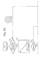
- Figure 9 is a routine for calculating an air-fuel ratio feedback correction coefficient FAF executed at every predetermined time period.
- step 901 it is determined whether or not all the feedback control (closed-loop control) conditions are satisfied.
- the feedback control conditions are as follows:
- a comparison reference value IR is calculated from a one-dimensional map stored in the ROM 107 by using the parameter KLEAN obtained by the routine of Fig. 3 or 6. Note that this one-dimensional map is shown in the block of step 903. That is, the comparison reference value IR is variable in accordance with the coefficient KLEAN, thereby changing the aimed air-fuel ratio of the feedback control in accordance with the coefficient KLEAN.
- step 904 the output LNSR of the lean mixture sensor 13 stored in the RAM 108 is compared with the comparison reference value IR, thereby determining whether the current air-fuel ratio is on the rich side or on the lean side with respect to the aimed air-fuel ratio. If LNSR ⁇ IR so that the current air-fuel ratio is on the rich side, the control proceeds to step 905 in which a lean skip flag CAFL is set, i.e., CAFL ⁇ "1". Note that the lean skip flag CAFL is used for a skip operation when a first change from the rich side to the lean side occurs in the controlled air-fuel ratio.
- step 906 it is determined whether or not a rich skip flag CAFR is "1".
- the skip flag CAFR is used for a skip operation when a first change from the lean side to the rich side occurs in the controlled air-fuel ratio.
- the control proceeds to step 907, which decreases the coefficient FAF by a relatively large amount SKP 1 .
- step 908 the rich skip flag CAFR is cleared, i.e., CAFR ⁇ "0".
- step 909 decreases the coefficient FAF by a relatively small amount K 1 .
- SKP1 is a constant for a skip operation which remarkably decreases the coefficient FAF when a first change from the lean side (LNSR > IR) to the rich side (LNSR ⁇ IR) occurs in the controlled air-fuel ratio
- K 1 is a constant for an integration operation which gradually decreases the coefficient FAF when the controlled air-fuel ratio is on the rich side.
- step 904 if LNSR > IR so that the current air-fuel ratio is on the lean side, the control proceeds to step 910 in which the rich skip flag CAFR is set, i.e., CAFR ⁇ "1". Then, at step 911, it is determined whether or not the lean skip flag CAFL is "1". As a result, if the lean skip flag CAFL is "1", the control proceeds to step 912, which increases the coefficient FAF by a relatively large amount SKP 2 . Then, at step 913, the lean skip flag CAFL is cleared, i.e., CAFL + "0".
- step 914 increases the coefficient FAF by a relatively small amount K 2 .
- SKP 2 is a constant for a skip operation which remarkably increases the coefficient FAF when a first change from the rich side (LNSR ⁇ IR) to the lean side (LNSR > IR) occurs in the controlled air-fuel ratio
- K 2 is a constant for an integration operation which gradually increases the coefficient FAF when the controlled air-fuel ratio is on the lean side.
- the air-fuel feedback correction coefficient FAF obtained at steps 907, 909, 912, 914, or 915 is stored in the RAM 108, and the routine of Fig. 9 is completed by step 917.
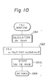
- Figure 10 is a routine for calculating a fuel injection time period TAU executed at every predetermined crank angle.
- this routine is executed at every 360°CA in a simultaneous fuel injection system for simultaneously injecting all the injectors and is executed at every 180°CA in a sequential fuel injection system applied to a four-cylinder engine for sequentially injecting the injectors thereof.
- a base fuel injection time period TAUP is calculated from a two-dimensional map stored in the ROM 107 by using the parameters PM and Ne. Then, at step 1002, a fuel injection time period TAU is calculated by TAU ⁇ TAUP ⁇ FAF ⁇ KLEAN ⁇ + ⁇ where a and are correction factors determined by other parameters such as the signal of the intake air temperature sensor, the voltage of the battery (both not shown), and the like. At step 1003, the calculated fuel injection time period TAU is stored on the RAM 108, and the routine of Fig. 10 is completed by step 1004.
- Figure 11 is a routine for controlling the fuel injection An Accordance with the fuel injection time period TAU calculated by the routine of Fig. 10, executed at every predetermined crank angle. Also, this routine is executed at every 360°CA in a simultaneous fuel injection system and is executed at every 180°CA in a sequential fuel injection system applied to a four-cylinder engine.
- the fuel injection time period TAU stored in the RAM 108 is read out and is transmitted to the D register (not shown) included in the CPU 105.
- an invalid fuel injection time period TAUV which is also stored in the RAM 108 is added to the content of the D register.
- the current time CNT of the free-run counter of the timer counter 106 is read out and is added to the content of the D register, thereby obtaining an injection end time t in the D register. Therefore, at step 1104, the content of the D register is stored as the injection end time t in the RAM 108.
- step 1105 the current time CNT of the free-run counter is read out and is set in the D register. Then, at step 1106, a small time period t 0 , which is definite or determined by the predetermined parameters, is added to the content of the D register. At step 1107, the content of the D register is set in the compare register of the timer counter 106, and at step 1108, a fuel injection execution flag and a compare interrupt permission flag are set in the registers of the timer counter 106. Then, the routine of Fig. 11 is completed by step 1109.
- an injection-on signal due to the presence of the fuel injection execution flag is transmitted from the time counter 106 via the I/O interface 103 to the driver circuit 104, thereby initiating a fuel injection by the fuel injector 8.
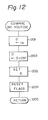
- a compare interrupt signal due to the presence of the compare interrupt permission flag is transmitted from the timer counter 106 to the CPU 105, thereby initiating a compare interrupt routine as illustrated in Fig. 12.
- step 1201 the injection end time t stored in the RAM 108 is read out and is transmitted to the D register. Then, at step 1202, the current time CNT of the free-run counter of the timer counter 106 is read out and is added to the content of the D register. At step 1203, the content of the D register, is set in the compare register of the timer counter 106, and at step 1204, the fuel injection execution flag and the compare interrupt permission flag are reset. Then, the routine of Fig. 12 is completed by step 1205.
- the fuel injection time period TAU is calculated by the routine of Fig. 10, which uses the coefficients KLEAN and FAF obtained by the routines of Figs. 3(6) and 9, the larger the coefficient KLEAN, the richer the controlled air-fuel ratio, while the smaller 'the coefficient KLEAN, the leaner the controlled air-fuel ratio.
- the air-fuel ratio is controlled in accordance with the coefficient KLEAN. Therefore, according to the present invention, since a lower limit is applied to the coefficient KLEAN, a limit on the lean side is applied to the controlled air-fuel ratio.
- the present invention can be also applied to a fuel injection system using the other parameters such as the intake air amount and the engine rotational speed, or the throttle opening value and the engine rotational speed.
- the air-fuel ratio during a warming-up mode can be controlled to be a value corresponding to the vaporization of fuel, and accordingly, the fuel consumption efficiency during an engine warming-up, mode can be improved without affecting the drivability characteristics.
Landscapes
- Engineering & Computer Science (AREA)
- Chemical & Material Sciences (AREA)
- Combustion & Propulsion (AREA)
- Mechanical Engineering (AREA)
- General Engineering & Computer Science (AREA)
- Electrical Control Of Air Or Fuel Supplied To Internal-Combustion Engine (AREA)
- Combined Controls Of Internal Combustion Engines (AREA)
Abstract
Description
- The present invention relates to a method and apparatus for feedback control of the air-fuel ratio in an internal combustion engine.
- As measures taken against exhaust gas pollution and fuel consumption, a lean burn system has recently been developed. According to this lean burn system, a lean mixture sensor is provided for generating an analog current in proportion to the air-fuel mixture on the lean side in an exhaust pipe of an engine. Thus, the feedback of the air-fuel ratio of the - engine can be controlled by using the analog output of the lean mixture sensor, thereby attaining an arbitrary air-fuel ratio on the lean side.
- In such a lean burn system, when the engine is in a warming-up mode, feedback control of the air-fuel ratio for the stoichimetric air-fuel ratio has also been carried out and the exhaust gas cleaned by a three-way catalytic converter. This, naturally, reduces the fuel consumption efficiency during a warming-up mode.
- In order to improve the fuel consumption efficiency during a warming-up mode, a lean burn system can be forcibly applied to the warming-up mode engine in the same way as to the after-warming-up mode engine. In this case, however, when the temperature of the engine is too low, vaporization of fuel within chambers of the engine is poor, so that the combustion of fuel is insufficient, inviting misfires and thus reducing drivability.
- It is an object of the present invention to provide a method and apparatus for controlling the air-fuel ratio in an internal combustion engine in which the feedback control of the air-fuel ratio on the lean side is possible without inviting misfiring of the engine even when the engine is in a warming-up mode, thereby improving the drivability.
- According to the present invention, in an internal combustion engine wherein feedback control of the air-fuel ratio is carried out in accordance with the concentration of a specific composition, such as oxygen, in the exhaust gas, so that the air-fuel ratio is close to an aimed air-fuel ratio on the lean side with respect to the stoichimetric air-fuel ratio, the aimed air-fuel ratio is variable in accordance with the engine temperature. As a result, when the engine is in a warming-up mode, i.e., when the temperature of the engine is low, - the aimed air-fuel ratio can be on the lean side with respect to the stoichimetric air-fuel ratio. In this case, when the temperature of the engine is too low, the aimed air-fuel ratio can be rich, however, on the lean side with respect to the stoichimetric air-fuel ratio.
- The present invention will be more clearly understood from the description as set forth below with reference to the accompanying drawings, wherein:
- Fig. 1 is a schematic diagram of an internal combustion engine according to the present invention;
- Fig. 2 is a graph showing the output characteristics of the lean mixture sensor of Fig. 1;
- Figs. 3, 6, and 9 to 12 are flow charts showing the operation of the control circuit of Fig. 1;
- Figs. 4 and 5 are graphs for explaining the flow chart of Fig. 3; and
- Figs. 7 and 8 are graphs for explaining the flow chart of Fig. 6.
- In Fig. 1, which illustrates an internal combustion engine according to the present invention,
reference numeral 1 designates a four-cycle spark ignition engine disposed in an automotive vehicle. Provided in an air-intake passage 2 of theengine 1 is asurge tank 3 in which apressure sensor 4 is provided. Thepressure sensor 4 is used for detecting the absolute pressure within the intake-air passage 2 and transmits its output signal to a multiplexer-incorporating analog-to-digital (A/D) converter 101 of acontrol circuit 10. - Disposed in a
distributor 5 arecrank angle sensors engine 1. In this case, the crank-angle sensor 6 generates a pulse signal at every 720° crank angle (CA) while the crank-angle sensor 7 generates a pulse signal at every 30°CA. The pulse signals of thecrank angle sensors interface 103 of thecontrol circuit 10. In addition, the pulse signal of thecrank angle sensor 7 is then supplied to an interruption terminal of a central processing unit (CPU) 105. - Additionally provided in the air-
intake passage 2 is afuel injector 8 for supplying pressurized fuel from the fuel system (not shown) to the air-intake port of the cylinder of theengine 1. In this case, other fuel injectors are also provided for other cylinders, though not shown in Fig. 1. - Disposed in a
cylinder block 9 of theengine 1 is acoolant temperature sensor 11 for detecting the temperature of the coolant. Thecoolant temperature sensor 11 generates an analog voltage signal in response to the temperature of the coolant and transmits it to the A/D converter 101 of thecontrol circuit 10. - Provided in an
exhaust gas passage 12 of theengine 1 is alean mixture sensor 13 for detecting the concentration of oxygen composition in the exhaust gas. Thelean mixture sensor 13 generates a current signal LNSR as shown in Fig. 2 and transmits it via a current-to-voltage converter circuit 102 of thecontrol circuit 10 to the A/D converter 101 thereof. - The
control circuit 10, which may be constructed by a microcomputer, includes adriver circuit 104 for driving thefuel injector 8, atimer counter 106, a read-only memory (ROM) 107 for storing a main routine, interrupt routines such as a fuel injection routine, an ignition timing routine, tables (maps), constants, etc., a random access memory 108 (RAM) for storing temporary data, aclock generator 109 for generating various clock signals, and the like, in addition to the A/D converter 101, the current-to-voltage converter circuit 102, the I/O interface 103, and theCPU 105. - The
timer counter 106 may include a free-run counter, a compare register, a comparator for comparing the content of the free-run counter with that of-the compare register, flag registers for compare interruption, injection control, and the like. Of course, the timer counter l06 also may include a plurality of compare registers and a plurality of comparators. In this case, thetimer counter 106 is used for controlling the injection start and end operation. - Interruptions occur at the
CPU 105, when the A/D converter 101 completes an A/D conversion and generates an interrupt signal; when thecrank angle sensor 7 generates a pulse signal; when thetimer counter 106 generates a compare interrupt signal; and when theclock generator 109 generates a special clock signal. - The pressure data PM of the
pressure sensor 4, the coolant temperature data THW, and the current data LNSR of thelean mixture sensor 13 are fetched by an A/D conversion routine(s) executed at every predetermined time period and are then stored in theRAM 108. That is, the data PM, THW, and LNSR in theRAM 108 are renewed at every predetermined time period. The engine rotational speed Ne is calculated by an interrupt routine executed at 30°CA, i.e., at every pulse signal of thecrank angle sensor 7, and is then stored in theRAM 108. - The operation of the
control circuit 10 of Fig. 1 will be explained with reference to the flow charts of Figs. 3, 6, and 9 through 12. - Figure 3 is a routine for calculating a lean air-fuel ratio correction coefficient KLEAN executed at every predetermined time period. Note that the coefficient KLEAN satisfies the condition: KLEAN < 1.0.
- At
step 301, KLEANPM is calculated from a one-dimensional map stored in theROM 107 by using the parameter PM as shown in the block ofstep 301. Also, atstep 302, KLEANNE is calculated from a one-dimensional map stored in theROM 107 by using the parameter Ne as shown on the block ofstep 302. Then atstep 303, KLEAN ← KLEANPM·KLEANNE. - At
step 304, it is determined whether or not the coolant temperature THW stored in theRAM 108 is lower than a predetermined temperature T1, which is, for example, 55°C, while atstep 307, it is determined whether or not the coolant temperature THW is higher than a predetermined temperature T2, which is, for example, 80°C. That is, the temperature T2 is higher than the temperature T1. Note that a warming-up operation is usually completed, when the coolant temperature THW reaches the temperature T2. - When THW < T1, then the proceeds to steps 305 and 306 in which the lean air-fuel ratio correction coefficient KLEAN is guarded by a lower limit value C1 which is relatively large and is, for example, 1.0. That is, at
step 305, it id determined whether or not the coefficient KLEAN is smaller then the lower limit value Cl. If KLEAN < C, , then atstep 306, KLEAN ← Cl. Otherwise, the control proceeds directly tostep 310. - When T1 ≦ THW ≦ T2, then the control proceeds to steps 308 and 309 in which the lean air-fuel ratio correction coefficient KLEAN is guarded by a lower limit value C2. The lower limit value C2 is smaller than the lower limit value C1, and is, for example, 0.6 to 0.8. That is, at
step 308, it is determined whether or not the coefficient KLEAN is smaller than the lower limit value C2. If KLEAN < C2, then atstep 309, KLEAN ← C2. Otherwise, the control proceeds directly tostep 310. - When THW > T2 , then the control proceeds directly to
step 310. That is, in this case, since it is considered that a warming-up operation is completed, no limitation is applied to the lean air-fuel correction coefficient KLEAN. - Thus, the finally obtained lean air-fuel ratio correction coefficient KLEAN is stored in the
RAM 108 atstep 310. The routine of Fig. 3 is completed bystep 311. - The lean air-fuel ratio correction coefficient KLEAN calculated by the routine of Fig. 3 will be explained with reference to Fig. 4. As shown in Fig. 4, if THW < T1, the coefficient KLEAN is controlled to be larger than the limit value C1. If T1 ≦ THW ≦ T2, the coefficient KLEAN is controlled to be larger than the limit value C2. If THW > T2 , no limitation is applied to the coefficient KLEAN derived by the parameters PM and Ne. Thus, the lower limit value of the lean air-fuel ratio correction coefficient KLEAN is controlled by the coolant temperature THW. Particularly, when the coolant temperature THW is low so that the vaporization of fuel is insufficient, the coefficient KLEAN is guarded by a large lower limit value, i.e., the value C1. As will be explained later, the controlled air-fuel ratio is determined by the coefficient KLEAN. Therefore, the air-fuel ratio is controlled in accordance with the coolant temperature THW. As a result, when the coolant temperature THW is low, the controlled lean air-fuel ratio becomes richer.,
- Note that a value TO of the coolant temperature THW is, for example, 50°C. In this case, the condition THW ≧ T0 is one of the feedback control conditions, which will be later explained. That is, if THW > T and the other feedback control conditions are satisfied, feedback control (closed-loop control) of the air-fuel ratio is carried out, while, if THW < T0, open-loop control of the air-fuel ratio is carried out.
- Figure 5 shows the lower limit characteristics of the controlled air-fuel ratio in the case where control of the air-fuel ratio is carried out by using the lean air-fuel ratio correction coefficient KLEAN obtained by the routine of Fig. 3. As shown in Fig. 5, the lower limit of the controlled air-fuel ratio is dependent upon the coolant temperature THW. That is, even during a warming-up mode (T1 ≦ THW ≦ T2), fuel combustion is carried out at a lean air-fuel ratio. Further, during a warming-up mode where the coolant temperature THW is too low (T0 ≦ THW < Tl), fuel combustion may be carried out at a lean air-fuel ratio. Thus, the fuel consumption efficiency during a warming-up mode is improved without reducing the combustion state.
- In Fig. 6, which is a modification of the routine of Fig. 3,
step 312 is added to the routine of Fig. 3, and steps 308' and 309' are provided instead ofsteps steps 312, 308' and 309' is carried out. That is, atstep 312, a lower limit value C is calculated from a one-dimensional v map stored in theROM 107 by using the parameter THW as shown in the block ofstep 312. At steps 308' and 309', the lean air-fuel ratio correction coefficient KLEAN is guarded by the lower limit value Cv. That is, at step 308', it is determined whether or not the coefficient KLEAN is smaller than the lower limit value Cv. If KLEAN < Cv, then at step 309', KLEAN ← C. Otherwise, the control proceeds directly to step 310. Thus, if T1 ≦ THW ≦ T2 , the lower limit value of the coefficient KLEAN is variable. - Figure 7 shows the lean air-fuel ratio correction coefficient KLEAN calculated by the routine of Fig. 6, and Fig. 8 shows the lower limit characteristics of the controlled air-fuel ratio in the case where control of the air-fuel ratio is carried out by using the lean air-fuel ratio correction coefficient KLEAN obtained by the routine of Fig. 6. As shown in Figs. 7 and 8, within the range of T1 ≦ THW < T2, the lower limit value of the coefficient is variable in accordance with the coolant temperature THW, carrying out fine air-fuel ratio control thereby obtaining further excellent improvement of the fuel consumption efficiency.
- Figure 9 is a routine for calculating an air-fuel ratio feedback correction coefficient FAF executed at every predetermined time period.
- At
step 901, it is determined whether or not all the feedback control (closed-loop control) conditions are satisfied. The feedback control conditions are as follows: - i) the engine is not in a starting state;
- ii) the incremental fuel injection is not being carried out; and
- iii) the coolant temperature THW is higher than the temperature TO (see Figs. 4, 5, 7, and 8).
- Of course, other feedback control conditions are introduced as occasion demands. However, an explanation of such other feedback control conditions is omitted.
- If at least one of the feedback control conditions is not satisfied, the control proceeds to step 915 in which the coefficient FAF is caused to be 1.0 (FAF = 1.0), thereby carrying out an open-loop control operation. Contrary-to this, if all the feedback control conditions are satisfied, the control proceeds to step 903.
- At
step 903, a comparison reference value IR is calculated from a one-dimensional map stored in theROM 107 by using the parameter KLEAN obtained by the routine of Fig. 3 or 6. Note that this one-dimensional map is shown in the block ofstep 903. That is, the comparison reference value IR is variable in accordance with the coefficient KLEAN, thereby changing the aimed air-fuel ratio of the feedback control in accordance with the coefficient KLEAN. - At
step 904, the output LNSR of thelean mixture sensor 13 stored in theRAM 108 is compared with the comparison reference value IR, thereby determining whether the current air-fuel ratio is on the rich side or on the lean side with respect to the aimed air-fuel ratio. If LNSR < IR so that the current air-fuel ratio is on the rich side, the control proceeds to step 905 in which a lean skip flag CAFL is set, i.e., CAFL ← "1". Note that the lean skip flag CAFL is used for a skip operation when a first change from the rich side to the lean side occurs in the controlled air-fuel ratio. - At
step 906, it is determined whether or not a rich skip flag CAFR is "1". Note that the skip flag CAFR is used for a skip operation when a first change from the lean side to the rich side occurs in the controlled air-fuel ratio. As a result, if the rich skip flag CAFR is "1", the control proceeds to step 907, which decreases the coefficient FAF by a relatively large amount SKP1. Then, atstep 908, the rich skip flag CAFR is cleared, i.e., CAFR ← "0". Thus, when the control atstep 906 is further carried out, then the control proceeds to step 909, which decreases the coefficient FAF by a relatively small amount K1. Here, SKP1 is a constant for a skip operation which remarkably decreases the coefficient FAF when a first change from the lean side (LNSR > IR) to the rich side (LNSR ≦ IR) occurs in the controlled air-fuel ratio, while K1 is a constant for an integration operation which gradually decreases the coefficient FAF when the controlled air-fuel ratio is on the rich side. - On the other hand, at
step 904, if LNSR > IR so that the current air-fuel ratio is on the lean side, the control proceeds to step 910 in which the rich skip flag CAFR is set, i.e., CAFR ← "1". Then, atstep 911, it is determined whether or not the lean skip flag CAFL is "1". As a result, if the lean skip flag CAFL is "1", the control proceeds to step 912, which increases the coefficient FAF by a relatively large amount SKP2. Then, at step 913, the lean skip flag CAFL is cleared, i.e., CAFL + "0". Thus, when the control atstep 911 is further carried out, then the control proceeds to step 914, which increases the coefficient FAF by a relatively small amount K2. Here, SKP2 is a constant for a skip operation which remarkably increases the coefficient FAF when a first change from the rich side (LNSR < IR) to the lean side (LNSR > IR) occurs in the controlled air-fuel ratio, while K2 is a constant for an integration operation which gradually increases the coefficient FAF when the controlled air-fuel ratio is on the lean side. - The air-fuel feedback correction coefficient FAF obtained at
steps RAM 108, and the routine of Fig. 9 is completed bystep 917. - Figure 10 is a routine for calculating a fuel injection time period TAU executed at every predetermined crank angle. For example, this routine is executed at every 360°CA in a simultaneous fuel injection system for simultaneously injecting all the injectors and is executed at every 180°CA in a sequential fuel injection system applied to a four-cylinder engine for sequentially injecting the injectors thereof.
- At
step 1001, a base fuel injection time period TAUP is calculated from a two-dimensional map stored in theROM 107 by using the parameters PM and Ne. Then, atstep 1002, a fuel injection time period TAU is calculated by
TAU ← TAUP·FAF·KLEAN·α+β where a and are correction factors determined by other parameters such as the signal of the intake air temperature sensor, the voltage of the battery (both not shown), and the like. At step 1003, the calculated fuel injection time period TAU is stored on theRAM 108, and the routine of Fig. 10 is completed bystep 1004. - Figure 11 is a routine for controlling the fuel injection An Accordance with the fuel injection time period TAU calculated by the routine of Fig. 10, executed at every predetermined crank angle. Also, this routine is executed at every 360°CA in a simultaneous fuel injection system and is executed at every 180°CA in a sequential fuel injection system applied to a four-cylinder engine.
- At step 1101, the fuel injection time period TAU stored in the
RAM 108 is read out and is transmitted to the D register (not shown) included in theCPU 105. Atstep 1102, an invalid fuel injection time period TAUV which is also stored in theRAM 108 is added to the content of the D register. In addition, atstep 1103, the current time CNT of the free-run counter of thetimer counter 106 is read out and is added to the content of the D register, thereby obtaining an injection end time t in the D register. Therefore, at step 1104, the content of the D register is stored as the injection end time t in theRAM 108. e - Again at
step 1105, the current time CNT of the free-run counter is read out and is set in the D register. Then, at step 1106, a small time period t0 , which is definite or determined by the predetermined parameters, is added to the content of the D register. Atstep 1107, the content of the D register is set in the compare register of thetimer counter 106, and atstep 1108, a fuel injection execution flag and a compare interrupt permission flag are set in the registers of thetimer counter 106. Then, the routine of Fig. 11 is completed bystep 1109. - Thus, when the current time CNT of the free-run counter reaches the compare register, an injection-on signal due to the presence of the fuel injection execution flag is transmitted from the
time counter 106 via the I/O interface 103 to thedriver circuit 104, thereby initiating a fuel injection by thefuel injector 8. Simultaneously, a compare interrupt signal due to the presence of the compare interrupt permission flag is transmitted from thetimer counter 106 to theCPU 105, thereby initiating a compare interrupt routine as illustrated in Fig. 12. - The completion of the fuel injection will be explained with reference to Fig. 12. At
step 1201, the injection end time t stored in theRAM 108 is read out and is transmitted to the D register. Then, atstep 1202, the current time CNT of the free-run counter of thetimer counter 106 is read out and is added to the content of the D register. Atstep 1203, the content of the D register, is set in the compare register of thetimer counter 106, and atstep 1204, the fuel injection execution flag and the compare interrupt permission flag are reset. Then, the routine of Fig. 12 is completed bystep 1205. - Thus, when the current time CNT of the free-run counter reaches the compare register, an injection-off signal due to the absence of the fuel injection execution flag is transmitted from the
timer counter 106 via the I/O interface 103 to thedriver circuit 104, thereby ending the fuel injection by thefuel injector 8. In this case, however, no compare interrupt signal is generated due to the absence of the compare interrupt permission flag. - Thus, fuel injection of the
fuel injector 8 is carried out for the time period TAU. - Since the fuel injection time period TAU is calculated by the routine of Fig. 10, which uses the coefficients KLEAN and FAF obtained by the routines of Figs. 3(6) and 9, the larger the coefficient KLEAN, the richer the controlled air-fuel ratio, while the smaller 'the coefficient KLEAN, the leaner the controlled air-fuel ratio. Thus, the air-fuel ratio is controlled in accordance with the coefficient KLEAN. Therefore, according to the present invention, since a lower limit is applied to the coefficient KLEAN, a limit on the lean side is applied to the controlled air-fuel ratio.
- Note that the present invention can be also applied to a fuel injection system using the other parameters such as the intake air amount and the engine rotational speed, or the throttle opening value and the engine rotational speed.
- As explained above, according to the present invention, since feedback control for an aimed air-fuel ratio on the lean side is carried out even during a warming-up mode, and in addition, the aimed air-fuel ratio is variable in accordance with the engine temperature, the air-fuel ratio during a warming-up mode can be controlled to be a value corresponding to the vaporization of fuel, and accordingly, the fuel consumption efficiency during an engine warming-up, mode can be improved without affecting the drivability characteristics.
Claims (10)
Applications Claiming Priority (2)
| Application Number | Priority Date | Filing Date | Title |
|---|---|---|---|
| JP59085105A JPS60230532A (en) | 1984-04-28 | 1984-04-28 | Air-fuel ratio controller for internal-combustion engine |
| JP85105/84 | 1984-04-28 |
Publications (3)
| Publication Number | Publication Date |
|---|---|
| EP0163134A2 true EP0163134A2 (en) | 1985-12-04 |
| EP0163134A3 EP0163134A3 (en) | 1986-02-19 |
| EP0163134B1 EP0163134B1 (en) | 1991-09-25 |
Family
ID=13849331
Family Applications (1)
| Application Number | Title | Priority Date | Filing Date |
|---|---|---|---|
| EP19850105059 Expired - Lifetime EP0163134B1 (en) | 1984-04-28 | 1985-04-25 | Method and apparatus for controlling air-fuel ratio in internal combustion engine |
Country Status (4)
| Country | Link |
|---|---|
| US (1) | US4644921A (en) |
| EP (1) | EP0163134B1 (en) |
| JP (1) | JPS60230532A (en) |
| DE (1) | DE3584186D1 (en) |
Cited By (4)
| Publication number | Priority date | Publication date | Assignee | Title |
|---|---|---|---|---|
| DE3613570A1 (en) * | 1985-04-22 | 1986-10-23 | Nissan Motor Co., Ltd., Yokohama, Kanagawa | FEEDBACK CONTROL SYSTEM FOR THE AIR / FUEL RATIO, SUITABLE FOR CURRENT CONTROL WITH OPEN CONTROL LOOP AT TRANSITION STATES |
| DE3733052A1 (en) * | 1986-09-30 | 1988-04-07 | Mitsubishi Electric Corp | CONTROL SYSTEM FOR THE FUEL-AIR MIXING RATIO IN INTERNAL COMBUSTION ENGINES |
| DE3826573A1 (en) * | 1987-08-08 | 1989-02-16 | Mitsubishi Electric Corp | DEVICE FOR MONITORING THE AIR / FUEL RATIO OF AN INTERNAL COMBUSTION ENGINE |
| EP1327759A3 (en) * | 2002-01-11 | 2008-03-05 | Nissan Motor Co., Ltd. | An apparatus and method for exhaust gas purification in an internal combustion engine |
Families Citing this family (14)
| Publication number | Priority date | Publication date | Assignee | Title |
|---|---|---|---|---|
| JPS6217336A (en) * | 1985-07-16 | 1987-01-26 | Mazda Motor Corp | Engine fuel injection controller |
| JPH06100114B2 (en) * | 1985-09-19 | 1994-12-12 | 本田技研工業株式会社 | Air-fuel ratio control method for internal combustion engine for vehicle |
| JPS62129754A (en) * | 1985-11-29 | 1987-06-12 | Honda Motor Co Ltd | Control method for oxygen concentration detection device |
| US4763629A (en) * | 1986-02-14 | 1988-08-16 | Mazda Motor Corporation | Air-fuel ratio control system for engine |
| JPS62171636U (en) * | 1986-04-22 | 1987-10-30 | ||
| JPH03179147A (en) * | 1989-12-06 | 1991-08-05 | Japan Electron Control Syst Co Ltd | Air-fuel ratio learning control device for internal combustion engines |
| JPH03225045A (en) * | 1990-01-31 | 1991-10-04 | Toyota Motor Corp | Air-fuel ratio control device for internal combustion engines |
| US5107815A (en) * | 1990-06-22 | 1992-04-28 | Massachusetts Institute Of Technology | Variable air/fuel engine control system with closed-loop control around maximum efficiency and combination of otto-diesel throttling |
| JPH04134147A (en) * | 1990-09-26 | 1992-05-08 | Honda Motor Co Ltd | Air-fuel ratio control method for internal combustion engines |
| JP2678985B2 (en) * | 1991-09-18 | 1997-11-19 | 本田技研工業株式会社 | Air-fuel ratio control device for internal combustion engine |
| US5474052A (en) * | 1993-12-27 | 1995-12-12 | Ford Motor Company | Automated method for cold transient fuel compensation calibration |
| US5715796A (en) * | 1995-02-24 | 1998-02-10 | Honda Giken Kogyo Kabushiki Kaisha | Air-fuel ratio control system having function of after-start lean-burn control for internal combustion engines |
| JP3550839B2 (en) * | 1995-12-01 | 2004-08-04 | 日産自動車株式会社 | Control device for internal combustion engine |
| JP3656777B2 (en) * | 1996-05-17 | 2005-06-08 | 本田技研工業株式会社 | Idle operation control device for internal combustion engine |
Family Cites Families (7)
| Publication number | Priority date | Publication date | Assignee | Title |
|---|---|---|---|---|
| GB1515734A (en) * | 1974-10-21 | 1978-06-28 | Nissan Motor | Apparatus for controlling the ratio of air to fuel of air-fuel mixture of internal combustion engine |
| JPS52125930A (en) * | 1976-04-14 | 1977-10-22 | Nippon Soken Inc | Air-fuel ratio control apparatus |
| US4169440A (en) * | 1977-12-01 | 1979-10-02 | The Bendix Corporation | Cruise economy system |
| JPS5623545A (en) * | 1979-08-02 | 1981-03-05 | Fuji Heavy Ind Ltd | Air-fuel ratio controller |
| JPS57143143A (en) * | 1981-02-26 | 1982-09-04 | Toyota Motor Corp | Air-to-fuel ratio control device |
| JPS58172443A (en) * | 1982-04-05 | 1983-10-11 | Toyota Motor Corp | Air fuel ratio control method |
| JPH0713493B2 (en) * | 1983-08-24 | 1995-02-15 | 株式会社日立製作所 | Air-fuel ratio controller for internal combustion engine |
-
1984
- 1984-04-28 JP JP59085105A patent/JPS60230532A/en active Granted
-
1985
- 1985-04-25 DE DE8585105059T patent/DE3584186D1/en not_active Expired - Lifetime
- 1985-04-25 EP EP19850105059 patent/EP0163134B1/en not_active Expired - Lifetime
- 1985-04-25 US US06/727,262 patent/US4644921A/en not_active Expired - Lifetime
Cited By (4)
| Publication number | Priority date | Publication date | Assignee | Title |
|---|---|---|---|---|
| DE3613570A1 (en) * | 1985-04-22 | 1986-10-23 | Nissan Motor Co., Ltd., Yokohama, Kanagawa | FEEDBACK CONTROL SYSTEM FOR THE AIR / FUEL RATIO, SUITABLE FOR CURRENT CONTROL WITH OPEN CONTROL LOOP AT TRANSITION STATES |
| DE3733052A1 (en) * | 1986-09-30 | 1988-04-07 | Mitsubishi Electric Corp | CONTROL SYSTEM FOR THE FUEL-AIR MIXING RATIO IN INTERNAL COMBUSTION ENGINES |
| DE3826573A1 (en) * | 1987-08-08 | 1989-02-16 | Mitsubishi Electric Corp | DEVICE FOR MONITORING THE AIR / FUEL RATIO OF AN INTERNAL COMBUSTION ENGINE |
| EP1327759A3 (en) * | 2002-01-11 | 2008-03-05 | Nissan Motor Co., Ltd. | An apparatus and method for exhaust gas purification in an internal combustion engine |
Also Published As
| Publication number | Publication date |
|---|---|
| EP0163134A3 (en) | 1986-02-19 |
| EP0163134B1 (en) | 1991-09-25 |
| DE3584186D1 (en) | 1991-10-31 |
| JPH0531646B2 (en) | 1993-05-13 |
| JPS60230532A (en) | 1985-11-16 |
| US4644921A (en) | 1987-02-24 |
Similar Documents
| Publication | Publication Date | Title |
|---|---|---|
| US5165230A (en) | Apparatus for determining deterioration of three-way catalyst of internal combustion engine | |
| US4644921A (en) | Method and apparatus for controlling air-fuel ratio in internal combustion engine | |
| US4964272A (en) | Air-fuel ratio feedback control system including at least downstreamside air-fuel ratio sensor | |
| US4475517A (en) | Air-fuel ratio control method and apparatus for an internal combustion engine | |
| EP0908613B1 (en) | Engine exhaust gas control system having NOx catalyst | |
| US5278762A (en) | Engine control apparatus using exhaust gas temperature to control fuel mixture and spark timing | |
| US5857445A (en) | Engine control device | |
| EP0162365B1 (en) | Method and apparatus for controlling the air-fuel ratio in internal combustion engine | |
| US4627402A (en) | Method and apparatus for controlling air-fuel ratio in internal combustion engine | |
| US4469072A (en) | Method and apparatus for controlling the fuel-feeding rate of an internal combustion engine | |
| EP0166447B1 (en) | Method and apparatus for controlling air-fuel ratio in internal combustion engine | |
| US4667631A (en) | Method and apparatus for controlling air-fuel ratio in internal combustion engine | |
| US4648370A (en) | Method and apparatus for controlling air-fuel ratio in internal combustion engine | |
| US4854124A (en) | Double air-fuel ratio sensor system having divided-skip function | |
| US7448360B2 (en) | Controller of internal combustion engine | |
| JPH0429860B2 (en) | ||
| EP0160959B1 (en) | Method and apparatus for detecting surging in internal combustion engine | |
| EP0160949A2 (en) | Method and apparatus for controlling air-fuel ratio in sequential injection type internal combustion engine | |
| EP0161611B1 (en) | Method and apparatus for controlling air-fuel ratio in internal combustion engine | |
| US4694805A (en) | Air-fuel ratio control method for internal combustion engines | |
| JP2803160B2 (en) | Output fluctuation detection device for multi-cylinder engine | |
| JP2609126B2 (en) | Air-fuel ratio feedback control device for internal combustion engine | |
| JPH0642384A (en) | Lean limit control method by ion current | |
| JPH0599041A (en) | Electronically controlled fuel injection equipment for internal combustion engine | |
| JPS61232347A (en) | Air-fuel ratio control device for internal combustion engines |
Legal Events
| Date | Code | Title | Description |
|---|---|---|---|
| PUAI | Public reference made under article 153(3) epc to a published international application that has entered the european phase |
Free format text: ORIGINAL CODE: 0009012 |
|
| 17P | Request for examination filed |
Effective date: 19850425 |
|
| AK | Designated contracting states |
Designated state(s): DE FR GB |
|
| PUAL | Search report despatched |
Free format text: ORIGINAL CODE: 0009013 |
|
| AK | Designated contracting states |
Designated state(s): DE FR GB |
|
| 17Q | First examination report despatched |
Effective date: 19890118 |
|
| GRAA | (expected) grant |
Free format text: ORIGINAL CODE: 0009210 |
|
| AK | Designated contracting states |
Kind code of ref document: B1 Designated state(s): DE FR GB |
|
| ET | Fr: translation filed | ||
| REF | Corresponds to: |
Ref document number: 3584186 Country of ref document: DE Date of ref document: 19911031 |
|
| RIN2 | Information on inventor provided after grant (corrected) |
Free format text: KOBAYASHI, NOBUYUKI * ITO, TOSHIMITSU |
|
| PLBE | No opposition filed within time limit |
Free format text: ORIGINAL CODE: 0009261 |
|
| STAA | Information on the status of an ep patent application or granted ep patent |
Free format text: STATUS: NO OPPOSITION FILED WITHIN TIME LIMIT |
|
| 26N | No opposition filed | ||
| REG | Reference to a national code |
Ref country code: GB Ref legal event code: 746 Effective date: 19940523 |
|
| REG | Reference to a national code |
Ref country code: FR Ref legal event code: D6 |
|
| PGFP | Annual fee paid to national office [announced via postgrant information from national office to epo] |
Ref country code: FR Payment date: 20010409 Year of fee payment: 17 |
|
| PGFP | Annual fee paid to national office [announced via postgrant information from national office to epo] |
Ref country code: DE Payment date: 20010418 Year of fee payment: 17 |
|
| PGFP | Annual fee paid to national office [announced via postgrant information from national office to epo] |
Ref country code: GB Payment date: 20010425 Year of fee payment: 17 |
|
| REG | Reference to a national code |
Ref country code: GB Ref legal event code: IF02 |
|
| PG25 | Lapsed in a contracting state [announced via postgrant information from national office to epo] |
Ref country code: GB Free format text: LAPSE BECAUSE OF NON-PAYMENT OF DUE FEES Effective date: 20020425 |
|
| PG25 | Lapsed in a contracting state [announced via postgrant information from national office to epo] |
Ref country code: DE Free format text: LAPSE BECAUSE OF NON-PAYMENT OF DUE FEES Effective date: 20021101 |
|
| GBPC | Gb: european patent ceased through non-payment of renewal fee |
Effective date: 20020425 |
|
| PG25 | Lapsed in a contracting state [announced via postgrant information from national office to epo] |
Ref country code: FR Free format text: LAPSE BECAUSE OF NON-PAYMENT OF DUE FEES Effective date: 20021231 |
|
| REG | Reference to a national code |
Ref country code: FR Ref legal event code: ST |