EP0162002A1 - Transporteur pour moissonneuse - Google Patents
Transporteur pour moissonneuse Download PDFInfo
- Publication number
- EP0162002A1 EP0162002A1 EP85630067A EP85630067A EP0162002A1 EP 0162002 A1 EP0162002 A1 EP 0162002A1 EP 85630067 A EP85630067 A EP 85630067A EP 85630067 A EP85630067 A EP 85630067A EP 0162002 A1 EP0162002 A1 EP 0162002A1
- Authority
- EP
- European Patent Office
- Prior art keywords
- belt
- belts
- cleats
- elastomeric body
- top surface
- Prior art date
- Legal status (The legal status is an assumption and is not a legal conclusion. Google has not performed a legal analysis and makes no representation as to the accuracy of the status listed.)
- Granted
Links
- 230000003014 reinforcing effect Effects 0.000 claims description 4
- 239000013536 elastomeric material Substances 0.000 claims description 3
- 230000002093 peripheral effect Effects 0.000 claims 1
- 229920001971 elastomer Polymers 0.000 abstract description 10
- 239000005060 rubber Substances 0.000 abstract description 8
- YOBAEOGBNPPUQV-UHFFFAOYSA-N iron;trihydrate Chemical group O.O.O.[Fe].[Fe] YOBAEOGBNPPUQV-UHFFFAOYSA-N 0.000 abstract 1
- 239000000463 material Substances 0.000 description 8
- 239000002184 metal Substances 0.000 description 7
- 230000000712 assembly Effects 0.000 description 5
- 238000000429 assembly Methods 0.000 description 5
- 230000007246 mechanism Effects 0.000 description 5
- 230000002787 reinforcement Effects 0.000 description 5
- 239000004744 fabric Substances 0.000 description 4
- 239000004760 aramid Substances 0.000 description 3
- 229920003235 aromatic polyamide Polymers 0.000 description 3
- 230000000295 complement effect Effects 0.000 description 3
- 239000011152 fibreglass Substances 0.000 description 3
- 238000003306 harvesting Methods 0.000 description 3
- 238000012423 maintenance Methods 0.000 description 3
- 241001124569 Lycaenidae Species 0.000 description 2
- 239000004677 Nylon Substances 0.000 description 2
- 229910000831 Steel Inorganic materials 0.000 description 2
- 230000015572 biosynthetic process Effects 0.000 description 2
- 150000001875 compounds Chemical class 0.000 description 2
- 239000000806 elastomer Substances 0.000 description 2
- 238000005461 lubrication Methods 0.000 description 2
- 229920003052 natural elastomer Polymers 0.000 description 2
- 229920001194 natural rubber Polymers 0.000 description 2
- 229920001778 nylon Polymers 0.000 description 2
- 229920000728 polyester Polymers 0.000 description 2
- 238000012545 processing Methods 0.000 description 2
- 239000012858 resilient material Substances 0.000 description 2
- 239000010959 steel Substances 0.000 description 2
- 229920001875 Ebonite Polymers 0.000 description 1
- JOYRKODLDBILNP-UHFFFAOYSA-N Ethyl urethane Chemical compound CCOC(N)=O JOYRKODLDBILNP-UHFFFAOYSA-N 0.000 description 1
- 229920000297 Rayon Polymers 0.000 description 1
- 238000005299 abrasion Methods 0.000 description 1
- 238000005056 compaction Methods 0.000 description 1
- 239000002131 composite material Substances 0.000 description 1
- 238000010276 construction Methods 0.000 description 1
- 238000007796 conventional method Methods 0.000 description 1
- 230000001419 dependent effect Effects 0.000 description 1
- 238000013461 design Methods 0.000 description 1
- 238000011143 downstream manufacturing Methods 0.000 description 1
- 230000000694 effects Effects 0.000 description 1
- 239000000835 fiber Substances 0.000 description 1
- 238000002955 isolation Methods 0.000 description 1
- 239000000314 lubricant Substances 0.000 description 1
- 238000000034 method Methods 0.000 description 1
- 239000000203 mixture Substances 0.000 description 1
- 238000000465 moulding Methods 0.000 description 1
- 239000010908 plant waste Substances 0.000 description 1
- 239000004033 plastic Substances 0.000 description 1
- 229920003023 plastic Polymers 0.000 description 1
- 239000002964 rayon Substances 0.000 description 1
- 239000011435 rock Substances 0.000 description 1
- 238000000926 separation method Methods 0.000 description 1
- 238000010008 shearing Methods 0.000 description 1
- 239000010902 straw Substances 0.000 description 1
- 229920003048 styrene butadiene rubber Polymers 0.000 description 1
- 229920003051 synthetic elastomer Polymers 0.000 description 1
- 239000005061 synthetic rubber Substances 0.000 description 1
- 238000012360 testing method Methods 0.000 description 1
- 229920002725 thermoplastic elastomer Polymers 0.000 description 1
- 229920002803 thermoplastic polyurethane Polymers 0.000 description 1
- 229920001187 thermosetting polymer Polymers 0.000 description 1
- 150000003673 urethanes Chemical class 0.000 description 1
Images


Classifications
-
- B—PERFORMING OPERATIONS; TRANSPORTING
- B65—CONVEYING; PACKING; STORING; HANDLING THIN OR FILAMENTARY MATERIAL
- B65G—TRANSPORT OR STORAGE DEVICES, e.g. CONVEYORS FOR LOADING OR TIPPING, SHOP CONVEYOR SYSTEMS OR PNEUMATIC TUBE CONVEYORS
- B65G15/00—Conveyors having endless load-conveying surfaces, i.e. belts and like continuous members, to which tractive effort is transmitted by means other than endless driving elements of similar configuration
- B65G15/30—Belts or like endless load-carriers
- B65G15/50—Endless load-carriers consisting of a series of parallel ropes or belt strips
- B65G15/52—Endless load-carriers consisting of a series of parallel ropes or belt strips interconnected by transverse slats
-
- A—HUMAN NECESSITIES
- A01—AGRICULTURE; FORESTRY; ANIMAL HUSBANDRY; HUNTING; TRAPPING; FISHING
- A01D—HARVESTING; MOWING
- A01D61/00—Elevators or conveyors for binders or combines
- A01D61/02—Endless belts
-
- B—PERFORMING OPERATIONS; TRANSPORTING
- B65—CONVEYING; PACKING; STORING; HANDLING THIN OR FILAMENTARY MATERIAL
- B65G—TRANSPORT OR STORAGE DEVICES, e.g. CONVEYORS FOR LOADING OR TIPPING, SHOP CONVEYOR SYSTEMS OR PNEUMATIC TUBE CONVEYORS
- B65G2201/00—Indexing codes relating to handling devices, e.g. conveyors, characterised by the type of product or load being conveyed or handled
- B65G2201/02—Articles
Definitions
- This invention generally relates to crop harvesters and, more particularly, to an improved, flexible belt conveyor which may be used for moving harvested grain from one level in the combine harvester to a higher level.
- This invention is particularly useful in a drag conveying apparatus in which the material to be conveyed is trapped between a floor and the conveyor belt assembly to effect the upward transport of the material by dragging it up the incline. This is in contrast to the more common method of conveying where the transported material is carried on the upper portion of the belt. It also is useful in hay balers for the formation, containment and compaction of the cut hay into large cylindrical bales.
- Drag conveyors as are known in the prior art are composed of mechanical chains with metal crossbars traversing the open distance between the chains. These chains are composed of a multiplicity of parts, including plates, pins, brackets and miscellaneous linkage parts. These mechanical chain conveyors suffer from a number of problems deriving from the many parts involved in the chain configuration. These mechanical chains are subject to stretching due to wearing and elongation of the holes through which the link pins or other fastening means are located. Over a relatively short period of operation of the harvester, the mechanical chain will actually expand in overall length by several inches requiring constant adjusting during harvesting operations to take up the slack created.
- An advantage of this invention is to provide a flexible endless belt conveyor that eliminates the maintenance requirements, damage potential, and excessive weight of prior art conveyors.
- the present invention substantially eliminates moving mechanical parts thus avoiding damage to downstream crop processing mechanisms in the harvester. It further provides quiet operation without need for lubricants.
- the design provides easy replacement of crossmembers which are damaged during operation. Much higher speeds of operation of the conveying mechanism can be attained through use of this invention.
- a crop conveying assembly comprising: a plurality of side by side, spaced apart, flexible belts; and a plurality of connecting links positioned transversely between said side by side belts, each of said belts having an elastomeric body with a top surface, a bottom surface, a longitudinally substantially inextensible tensile member disposed within said elastomeric body, a plurality of longitudinally spaced integrally molded lugs on the bottom surface, a plurality of longitudinally spaced raised cleats integrally molded to the top surface, each of said cleats having an aperture extending transversely therethrough and wherein the cleats of each adjacent side by side belt being positioned such that the apertures therein are transversely aligned and wherein the plurality of connecting links are positioned transversely of the belts by positioning the ends of the connecting links within the apertures of adjacent side by side belts.
- a conveyor for a combine harvester 8 is generally indicated by a reference numeral 10.
- the forward end 11 is positioned in a harvester such as a combine 8 toward the crop gathering forward end of the combine.
- An auger 9 may feed the conveyor.
- the rearward end 12 discharges the crop into an additional processing step in the combine such as a cylinder 7, straw walker, or separation and sieve mechanisms.
- the harvester conveyor 11 includes a shroud 13 which completely encloses the conveyor during operation.
- the shroud 13 includes an inclined conveyor bottom surface 14.
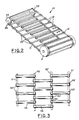
- the conveyor shown in Fig. 1 and Fig. 2 includes two or more juxtaposed, adjacent belts 15 and 15' which are rotatably mounted on drive and idler means which are shown in Fig. 1 as a pair of toothed pulleys 25 and 25' and an idler drum 5.
- Positioned transversely between the belts 15 and 15' are connecting links 16.
- the belts 15 and 15' and connecting links 16 are shown in isolation in Fig. 2.
- the belts 15 and 15' are identical in construction.
- the belt 15 is composed of an elastomeric body 20 made from an elastomeric and resilient material suitable for the working environment.
- the elastomeric body 20 may be a unitary structure or may include a first layer 21 and a second layer 22 which are substantially parallel and composed of the same or different elastomeric and resilient materials.
- elastomeric materials which may be used include thermosetting natural or synthetic rubbers, thermoplastic elastomers and urethanes.
- the first layer 21 includes integrally molded elastomeric cleats 23 to form the top surface 41.
- the cleats 23 are spaced regularly around the full longitudinal or circumferential length of the belt 15.
- the second layer 22 forms a positive driving portion of the belt 15 and includes a plurality of longitudinally spaced lugs 24, integrally molded to the second layer to form the bottom surface 42.
- the lugs may have any desired spacing for meshing with a tooth pulley or sprocket.
- a single row of lugs may be utilized, however, it is preferable that there be two rows of lugs on the second layer spaced transversely apart.
- the lugs of each longitudinal row should be preferably aligned transversely with lugs of the adjacent lug row.
- the sprockets 25, 25' utilized in the crop conveying assembly of Fig. 2 contain lug engaging teeth 26. While Fig.
- the tensile member 31 is Imbedded within the polymeric body 20 or alternatively positioned between the first layer 21 and second layer 22.
- the tensile member should be substantially inextensible in the range of working tension exerted during use in a crop conveying assembly.
- the tensile member 31 may be composed of any conventionally used high modulus of elongation material which exhibits elongation in an acceptable range for the tension which is exerted on the belt 15 during operation. Steel wire, fiberglass, or aromatic polyamide are preferred high modulus load bearing members due to their low elongation at high tensile stresses.
- Other conventional tensile members such as polyester, nylon and rayon may be used for lighter duty applications where the working tension placed on the belt during operation is relatively low.
- the tensile member may be formed in any conventionally known manner including spiralling one or more strands onto a forming mandrel to form a continuous, endless tensile member.
- strips of reinforcement having a longitudinally oriented tensile material such as tire cord fabric may also be overlap spliced to form a continuous tensile member, which has sufficient splice strength to remain substantially inextensible at operating tensions.
- Additional plies of reinforcing fabric may be positioned over and/or under the load bearing tensile member 31.
- the reinforcement layers may be formed of any conventional belt fabric such as square-woven, bias fabrics or cords to impart additional longitudinal and transverse strength and to protect the tensile member from damage during service.
- the cleats 23 contain an aperture 27 extending transversely through the cleat, having an axis generally parallel to the top surface of the belt and perpendicular to the direction of the cords in the tensile member or the longitudinal axis of the belt.
- Connecting links 16 are positioned such that the extreme ends 17 of the connecting links 16 are adapted to extend through the cleat aperture 27, which is complementary thereto.
- Connecting links 16 form the crop engaging portion of the crop conveying assembly.
- the connecting links 16 scrape along bottom surface or pan to trap the grain in front of the leading edge to transport the grain up the inclined bottom surface.
- the connecting links 16 are elongated structures having a relatively uniform cross-section through the central portion of their length.
- the cross-section may be any shape, including rectangular, trapezoidal, square, round, oblong, triangular, or T-shaped.
- the axially extreme end portions 17 of each connecting link may preferably have a cross-section of lesser height than the central portion 18 of the link. Height refers to that dimension of the connecting link which lies perpendicular to the plane of the belt tensile member.
- the cross-section of the end portions may either be of the same shape as the central portion or it may be a different shape.
- the connecting links 16 may be composed of metal, rubber, rubber reinforced with a rigid rod extending through its length, reinforced fiberglass, rubber or urethane. Any material which is suitably resistant to deformation may be utilized. The most preferred embodiment is a reinforced rubber connecting link due to its ability to deflect during severe impact and rebound to the original shape with no permanent disformation.
- the connecting links may optionally-be secured in position within the aperture 27 through the use of set screws, pins extending therethrough or other means for limiting movement in the transverse direction to the belt.
- a preferred configuration is shown in Fig. 4 where the aperture 27 is reinforced by use of hard rubber, metal or plastic inserts 28 which are bored to accommodate and match the cross-sectional profile of the end of the connecting links 16. The inserts improve the capability of each cleat to resist ripping during the application of severe longitudinal shear stresses during harvesting operations.
- An optional cleat reinforcement layer 48 is shown extending within the elastomeric cleat body over the aperture 27 and extending down to run generally parallel to the load bearing tensile member 31. It follows a generally sinusoidal path essentially parallel to the top surface 41 of the belt. This cleat reinforcement layer 48 is useful in dissipating shear stresses which develop during operation of the crop conveying apparatus around the aperture 27. Specially reinforced elastomeric compounds may be utilized in the molding of the cleat portion in order to provide additional resistance to these shear stresses.
- Fig. 1 and Fig. 2 shows a conveyor having a single crop conveying assembly consisting of two parallel belts with connecting links extending between the two belts.
- Fig. 3 shows an alternative embodiment of a wide conveyor system which utilizes several side by side crop conveying assemblies in the conveyor.
- the outermost two belts 51 and 51' contain a single row of longitudinally spaced cleats 53 and 53' around their circumference while the center belts 52 and 52' contain double the number of cleats 54 and 54' on each belt to accommodate the juxtaposed sets of connecting links 56 positioned in the cleat apertures.
- Each successive cleat along the circumference of each center belt 52 and 52' receives the end of a connecting link from the opposite direction with all links being positioned transversely of the belt.
- Another alternative embodiment would be to have cleats on the center belts which have transverse widths great enough to accommodate connecting links ends inserted from both sides, wherein the innermost belts would have an equal number of cleats as the outermost belt
- the belts useful in this invention can be made according to conventional techniques for producing endless belts.
- a preferred endless belt uses a natural and styrene-butadiene rubber blend for the elastomeric body with a continuously wound, aromatic polyamide filament tensile member.
- the uncured belt composite is formed then subjected to heat and pressure to complete formation of the cleats and driving lugs and to cure the elastomer.
- Assembling the crop conveying assemblies is accomplished by inserting one end of the connecting links into the aperture provided in the cleats of one belt of the assembly, then sliding the opposite end of the connecting link into a transversely aligned aperture in a cleat of the second belt of the assembly.
- the crop gathering assembly of this invention is free of the operational difficulties associated with a belt assembly wherein a connecting link or a cleat is attached through a punched hole in the belt carcass. Any time a hale is punched through a belt carcass, this attachment point becomes a stress center during operations under tension, and the hole in the belt carcass will inevitably be the failure point.
- This invention allows for thinner, lighter weight belts, which can be run over small diameter sprockets and idlers at high speed, due to the relatively thin belt carcass required. When a hole is being punched through the belt carcass and tensile member, the carcass must be made correspondingly thicker and more heavily reinforced to accommodate the loss in load bearing capabilities.
- the crop conveying assemblies composed of two belts spaced apart with connecting links extending between the longitudinally aligned cleats of the belts offer a greatly improved system for conveying grain within a harvester, or for forming and compacting large cylindrical bales in a hay baler.
- Each assembly is lightweight, requires no lubrication, has no metal parts, and with proper selection of the load bearing tensile member, exhibits virtually no stretching during crop gathering operations. All these attributes lead to low maintenance, long life, operating economy and quiet conveyor operation. Additionally, the conveyor can be run at greatly increased speeds when compared to the prior art mechanical chain link systems. Further, the weight saving is substantial; a metal chain conveyor for a small combine weighs 200 pounds while the rubber crop conveyor of this invention weighs only 90 pounds.
Landscapes
- Engineering & Computer Science (AREA)
- Mechanical Engineering (AREA)
- Life Sciences & Earth Sciences (AREA)
- Environmental Sciences (AREA)
- Belt Conveyors (AREA)
Applications Claiming Priority (2)
| Application Number | Priority Date | Filing Date | Title |
|---|---|---|---|
| US609041 | 1984-05-10 | ||
| US06/609,041 US4553663A (en) | 1984-05-10 | 1984-05-10 | Conveyor for a crop harvester |
Publications (2)
| Publication Number | Publication Date |
|---|---|
| EP0162002A1 true EP0162002A1 (fr) | 1985-11-21 |
| EP0162002B1 EP0162002B1 (fr) | 1989-02-01 |
Family
ID=24439124
Family Applications (1)
| Application Number | Title | Priority Date | Filing Date |
|---|---|---|---|
| EP85630067A Expired EP0162002B1 (fr) | 1984-05-10 | 1985-04-30 | Transporteur pour moissonneuse |
Country Status (4)
| Country | Link |
|---|---|
| US (1) | US4553663A (fr) |
| EP (1) | EP0162002B1 (fr) |
| CA (1) | CA1219237A (fr) |
| DE (1) | DE3568024D1 (fr) |
Cited By (5)
| Publication number | Priority date | Publication date | Assignee | Title |
|---|---|---|---|---|
| GB2237255A (en) * | 1989-10-09 | 1991-05-01 | Douglas Charles Mcrae | Conveyor web or flexible ladder |
| FR2665331A1 (fr) * | 1990-07-31 | 1992-02-07 | Franquet Ets | Procede et machine de ramassage, de hachage, de chargement et de dechargement mecanique de fourrage. |
| US5671839A (en) * | 1993-03-19 | 1997-09-30 | Reekie Manufacturing Limited | Open web |
| WO2011012106A1 (fr) * | 2009-07-27 | 2011-02-03 | Artemis Kautschuk- Und Kunststoff-Technik Gmbh | Convoyeur oblique pour moissonneuses-batteuses |
| CN105165248A (zh) * | 2013-12-23 | 2015-12-23 | Ea布洛伊科马有限公司 | 甘蔗收割机 |
Families Citing this family (30)
| Publication number | Priority date | Publication date | Assignee | Title |
|---|---|---|---|---|
| US4736833A (en) * | 1986-04-24 | 1988-04-12 | J. I. Case Company | Combine feeder conveyor drag bar mounting mechanism |
| US4899868A (en) * | 1986-09-04 | 1990-02-13 | The Goodyear Tire & Rubber Company | Conveyor for a crop harvester |
| CA1296532C (fr) * | 1986-09-04 | 1992-03-03 | David Willard Johnson | Convoyeur pour un moissonneur |
| USD333544S (en) | 1990-11-10 | 1993-02-23 | Akira Uehara | Conveyor belt |
| US5168981A (en) * | 1991-06-18 | 1992-12-08 | Edwin Ruff | Belt chain |
| US5176248A (en) * | 1992-01-29 | 1993-01-05 | Lockwood Corporation | Belted chain |
| IT1270460B (it) * | 1993-02-16 | 1997-05-05 | Space Srl | Apparecchiatura motorizzata di carico e scarico per autocarri e simili |
| DE4401586A1 (de) * | 1994-01-20 | 1995-07-27 | Gummi Jaeger Kg Gmbh & Cie | Siebstabband |
| IT237017Y1 (it) * | 1995-07-07 | 2000-08-31 | Smi Sistemi Macchine Impianti | Dispositivo trasportatore particolarmente studiato per impiantidi confezionamento con film di materiali termoretraibili |
| WO2003013987A2 (fr) * | 2001-08-03 | 2003-02-20 | C.U.E., Inc. | Raclette de convoyeur |
| US6896125B2 (en) * | 2003-04-04 | 2005-05-24 | Pflow Industries, Inc. | Belt attachment device and method |
| US7475954B1 (en) * | 2005-10-12 | 2009-01-13 | May & Scofield Llc | Tambour closure |
| US20070251203A1 (en) * | 2006-04-26 | 2007-11-01 | Deere & Company, A Delaware Corporation | Dual conveyor system for a combine feeder house |
| US20080276591A1 (en) * | 2007-05-07 | 2008-11-13 | Claas Omaha, Inc. | Draper belt rib apparatus and method |
| US20110094201A1 (en) * | 2009-10-27 | 2011-04-28 | Duane Bomleny | Center Draper Belt With Crop Conveying Features |
| DE102014213445A1 (de) * | 2014-07-10 | 2016-01-14 | Deere & Company | Schrägfördererzusammenbau für einen Mähdrescher |
| DE102014215762A1 (de) * | 2014-08-08 | 2016-02-11 | Deere & Company | Schrägförderer für einen Mähdrescher mit flexiblen Zugmitteln und abnehmbaren Schraubbolzen zur Anbringung von Förderleisten |
| CA2999515C (fr) * | 2015-09-30 | 2020-09-08 | Contitech Transportbandsysteme Gmbh | Courroie de tuloteuse ayant une configuration de tasseaux |
| US10233022B2 (en) | 2015-09-30 | 2019-03-19 | Contitech Transportbandsysteme Gmbh | Draper belt having improved cleat design |
| EP3199477B1 (fr) | 2016-01-27 | 2019-07-17 | Prince Castle LLC | Lamelle pour une bande transporteuse à chaîne et pour un système de bande transporteuse |
| US10308433B2 (en) * | 2016-06-29 | 2019-06-04 | Prince Castle LLC | Conveyor belt slat with side carrier connection |
| WO2018172963A1 (fr) * | 2017-03-21 | 2018-09-27 | Soucy International Inc. | Courroie de convoyeur à toile |
| US10257982B2 (en) * | 2017-06-23 | 2019-04-16 | Macdon Industries Ltd. | Wear-inhibiting clip for draper cleat or slat of a crop harvesting header |
| US10687468B1 (en) * | 2018-12-18 | 2020-06-23 | Contitech Antriebssysteme Gmbh | Flexible synchronous toothed belt with narrow splice |
| DE102018222481A1 (de) * | 2018-12-20 | 2020-06-25 | Contitech Antriebssysteme Gmbh | Zugmittel, vorzugsweise Riemen, für einen Schrägförderer eines Mähdreschers |
| IT202000002242A1 (it) * | 2020-02-05 | 2021-08-05 | Roc Group S R L | Dispositivo convogliatore per una macchina agricola e macchina agricola comprendente detto dispositivo |
| DE102020103294A1 (de) * | 2020-02-10 | 2021-08-12 | Arntz Beteiligungs Gmbh & Co. Kg | Antriebsmittel für Förderbänder, insbesondere landwirtschaftlicher Maschinen und Verfahren zu dessen Herstellung |
| CN214127010U (zh) * | 2020-09-01 | 2021-09-07 | 深圳麦克韦尔科技有限公司 | 调气组件、调气带、电池设备和电子雾化装置 |
| AU2021206819A1 (en) * | 2021-07-20 | 2023-02-09 | Apap and Grima Pty Ltd | Improved Conveyor System |
| US12076881B2 (en) * | 2022-03-16 | 2024-09-03 | Kuang Yung Machinery Co., Ltd. | Delivery chain apparatus of a wood-working machine with saw blades |
Citations (4)
| Publication number | Priority date | Publication date | Assignee | Title |
|---|---|---|---|---|
| US2637436A (en) * | 1947-06-09 | 1953-05-05 | Deere & Co | Harvester gatherer belt |
| FR2410949A1 (fr) * | 1977-12-10 | 1979-07-06 | Grimme Landmaschf Franz | Courroies pour tabliers secoueurs de machines a recolter les pommes de terre |
| DE2917515A1 (de) * | 1979-04-30 | 1980-11-13 | Waldemar Glowatzki | Stabfoerderband |
| DE3246528A1 (de) * | 1982-12-16 | 1984-06-20 | Gummi-Jäger KG GmbH & Cie, 3000 Hannover | Gurtstabband fuer landwirtschaftliche maschinen |
Family Cites Families (5)
| Publication number | Priority date | Publication date | Assignee | Title |
|---|---|---|---|---|
| US404460A (en) * | 1889-06-04 | Straw-carrier | ||
| US626572A (en) * | 1899-06-06 | Canvas-fastener for belt carriers | ||
| US2305044A (en) * | 1939-04-28 | 1942-12-15 | Rub R Slat Co | Conveyer and elevator belt |
| US2575610A (en) * | 1947-12-27 | 1951-11-20 | Joy Mfg Co | Flight conveyer |
| DE2919913A1 (de) * | 1978-05-24 | 1979-11-29 | Molins Ltd | Zusammengesetztes foerder- oder antriebsband |
-
1984
- 1984-05-10 US US06/609,041 patent/US4553663A/en not_active Expired - Fee Related
-
1985
- 1985-04-30 DE DE8585630067T patent/DE3568024D1/de not_active Expired
- 1985-04-30 EP EP85630067A patent/EP0162002B1/fr not_active Expired
- 1985-05-09 CA CA000481166A patent/CA1219237A/fr not_active Expired
Patent Citations (4)
| Publication number | Priority date | Publication date | Assignee | Title |
|---|---|---|---|---|
| US2637436A (en) * | 1947-06-09 | 1953-05-05 | Deere & Co | Harvester gatherer belt |
| FR2410949A1 (fr) * | 1977-12-10 | 1979-07-06 | Grimme Landmaschf Franz | Courroies pour tabliers secoueurs de machines a recolter les pommes de terre |
| DE2917515A1 (de) * | 1979-04-30 | 1980-11-13 | Waldemar Glowatzki | Stabfoerderband |
| DE3246528A1 (de) * | 1982-12-16 | 1984-06-20 | Gummi-Jäger KG GmbH & Cie, 3000 Hannover | Gurtstabband fuer landwirtschaftliche maschinen |
Cited By (5)
| Publication number | Priority date | Publication date | Assignee | Title |
|---|---|---|---|---|
| GB2237255A (en) * | 1989-10-09 | 1991-05-01 | Douglas Charles Mcrae | Conveyor web or flexible ladder |
| FR2665331A1 (fr) * | 1990-07-31 | 1992-02-07 | Franquet Ets | Procede et machine de ramassage, de hachage, de chargement et de dechargement mecanique de fourrage. |
| US5671839A (en) * | 1993-03-19 | 1997-09-30 | Reekie Manufacturing Limited | Open web |
| WO2011012106A1 (fr) * | 2009-07-27 | 2011-02-03 | Artemis Kautschuk- Und Kunststoff-Technik Gmbh | Convoyeur oblique pour moissonneuses-batteuses |
| CN105165248A (zh) * | 2013-12-23 | 2015-12-23 | Ea布洛伊科马有限公司 | 甘蔗收割机 |
Also Published As
| Publication number | Publication date |
|---|---|
| US4553663A (en) | 1985-11-19 |
| CA1219237A (fr) | 1987-03-17 |
| EP0162002B1 (fr) | 1989-02-01 |
| DE3568024D1 (en) | 1989-03-09 |
Similar Documents
| Publication | Publication Date | Title |
|---|---|---|
| US4553663A (en) | Conveyor for a crop harvester | |
| US4899868A (en) | Conveyor for a crop harvester | |
| US4805388A (en) | Crop gathering head and belt, sprocket and sheave therefor | |
| US3853016A (en) | Crop gathering belt | |
| US3854272A (en) | Crop gathering belt | |
| US8596447B2 (en) | Inclined conveyor for a combine | |
| US4518647A (en) | Agricultural belting material | |
| EP3899319B1 (fr) | Courroie crantée synchrone souple à épissure étroite | |
| EP3381266B1 (fr) | Tambour avant de chambre d'alimentation à engrenage | |
| US4495755A (en) | Conveyor for a combine harvester | |
| US10925215B2 (en) | Slat-bar cross-members in a feederhouse crop-conveying system | |
| EP3381267B1 (fr) | Insert de lamelle d'atténuation de bruit/usure dans un convoyeur d'ameneur | |
| EP3409099B1 (fr) | Courroie et coupleur pour transporteur d'alimentation | |
| US11382272B2 (en) | Traction belt for an inclined conveyor of a combine harvester | |
| EP0259244B1 (fr) | Convoyeur pour moissonneuse-batteuse | |
| US4202159A (en) | Conveyor for a combine harvester | |
| EP3356263B1 (fr) | Courroie de convoyeur à toile ayant une durée de vie de bord améliorée | |
| CA1197693A (fr) | Moissonneuse avec courroie, pignon et roue a gorge | |
| CA1284032C (fr) | Transporteur mecanique sur tablier de moissonneuse-batteuse-lieuse | |
| CA1088322A (fr) | Bande transporteuse pour moissonneuse-batteuse | |
| RU238372U1 (ru) | Транспортер для наклонной камеры комбайна | |
| US20180020613A1 (en) | Belted chain connection system | |
| CA1223445A (fr) | Tete, courroie, barbotin et roue de renvoi pour moissonneuse | |
| WO2023114796A1 (fr) | Jonction de chevauchement de courroie de convoyeur à toile |
Legal Events
| Date | Code | Title | Description |
|---|---|---|---|
| PUAI | Public reference made under article 153(3) epc to a published international application that has entered the european phase |
Free format text: ORIGINAL CODE: 0009012 |
|
| 17P | Request for examination filed |
Effective date: 19850523 |
|
| AK | Designated contracting states |
Designated state(s): BE DE FR GB NL |
|
| 17Q | First examination report despatched |
Effective date: 19860924 |
|
| D17Q | First examination report despatched (deleted) | ||
| GRAA | (expected) grant |
Free format text: ORIGINAL CODE: 0009210 |
|
| AK | Designated contracting states |
Kind code of ref document: B1 Designated state(s): BE DE FR GB NL |
|
| REF | Corresponds to: |
Ref document number: 3568024 Country of ref document: DE Date of ref document: 19890309 |
|
| ET | Fr: translation filed | ||
| PLBE | No opposition filed within time limit |
Free format text: ORIGINAL CODE: 0009261 |
|
| STAA | Information on the status of an ep patent application or granted ep patent |
Free format text: STATUS: NO OPPOSITION FILED WITHIN TIME LIMIT |
|
| 26N | No opposition filed | ||
| PGFP | Annual fee paid to national office [announced via postgrant information from national office to epo] |
Ref country code: GB Payment date: 19990315 Year of fee payment: 15 |
|
| PGFP | Annual fee paid to national office [announced via postgrant information from national office to epo] |
Ref country code: NL Payment date: 19990322 Year of fee payment: 15 |
|
| PGFP | Annual fee paid to national office [announced via postgrant information from national office to epo] |
Ref country code: FR Payment date: 19990406 Year of fee payment: 15 |
|
| PGFP | Annual fee paid to national office [announced via postgrant information from national office to epo] |
Ref country code: DE Payment date: 19990430 Year of fee payment: 15 |
|
| PGFP | Annual fee paid to national office [announced via postgrant information from national office to epo] |
Ref country code: BE Payment date: 19990511 Year of fee payment: 15 |
|
| PG25 | Lapsed in a contracting state [announced via postgrant information from national office to epo] |
Ref country code: GB Free format text: LAPSE BECAUSE OF NON-PAYMENT OF DUE FEES Effective date: 20000430 Ref country code: BE Free format text: LAPSE BECAUSE OF NON-PAYMENT OF DUE FEES Effective date: 20000430 |
|
| BERE | Be: lapsed |
Owner name: THE GOODYEAR TIRE & RUBBER CY Effective date: 20000430 |
|
| PG25 | Lapsed in a contracting state [announced via postgrant information from national office to epo] |
Ref country code: NL Free format text: LAPSE BECAUSE OF NON-PAYMENT OF DUE FEES Effective date: 20001101 |
|
| GBPC | Gb: european patent ceased through non-payment of renewal fee |
Effective date: 20000430 |
|
| PG25 | Lapsed in a contracting state [announced via postgrant information from national office to epo] |
Ref country code: FR Free format text: LAPSE BECAUSE OF NON-PAYMENT OF DUE FEES Effective date: 20001229 |
|
| NLV4 | Nl: lapsed or anulled due to non-payment of the annual fee |
Effective date: 20001101 |
|
| PG25 | Lapsed in a contracting state [announced via postgrant information from national office to epo] |
Ref country code: DE Free format text: LAPSE BECAUSE OF NON-PAYMENT OF DUE FEES Effective date: 20010201 |
|
| REG | Reference to a national code |
Ref country code: FR Ref legal event code: ST |