EP0161952B1 - Procédé de conditionnement d'un object en alliage métallique à mémoire de forme à deux états de mémoire de forme réversibles - Google Patents
Procédé de conditionnement d'un object en alliage métallique à mémoire de forme à deux états de mémoire de forme réversibles Download PDFInfo
- Publication number
- EP0161952B1 EP0161952B1 EP85400523A EP85400523A EP0161952B1 EP 0161952 B1 EP0161952 B1 EP 0161952B1 EP 85400523 A EP85400523 A EP 85400523A EP 85400523 A EP85400523 A EP 85400523A EP 0161952 B1 EP0161952 B1 EP 0161952B1
- Authority
- EP
- European Patent Office
- Prior art keywords
- shape
- condition
- temperature
- memory
- state
- Prior art date
- Legal status (The legal status is an assumption and is not a legal conclusion. Google has not performed a legal analysis and makes no representation as to the accuracy of the status listed.)
- Expired - Lifetime
Links
- 238000000034 method Methods 0.000 title claims description 64
- 230000008569 process Effects 0.000 title claims description 29
- 230000002441 reversible effect Effects 0.000 title claims description 16
- 229910045601 alloy Inorganic materials 0.000 title description 4
- 239000000956 alloy Substances 0.000 title description 4
- 230000001939 inductive effect Effects 0.000 title 1
- 239000000463 material Substances 0.000 claims description 36
- 230000035882 stress Effects 0.000 claims description 33
- 238000010438 heat treatment Methods 0.000 claims description 19
- 229910000734 martensite Inorganic materials 0.000 claims description 17
- 229910001092 metal group alloy Inorganic materials 0.000 claims description 13
- 238000001816 cooling Methods 0.000 claims description 12
- 230000008859 change Effects 0.000 claims description 11
- 230000007704 transition Effects 0.000 claims description 11
- 238000011282 treatment Methods 0.000 claims description 9
- 230000003071 parasitic effect Effects 0.000 claims description 8
- 230000008646 thermal stress Effects 0.000 claims description 7
- -1 copper-zinc-aluminium Chemical compound 0.000 claims description 6
- 230000003750 conditioning effect Effects 0.000 claims description 4
- 230000000694 effects Effects 0.000 claims description 4
- 230000000750 progressive effect Effects 0.000 claims description 4
- 230000009467 reduction Effects 0.000 claims description 4
- 238000003303 reheating Methods 0.000 claims description 4
- LMBUSUIQBONXAS-UHFFFAOYSA-N [Ti].[Fe].[Ni] Chemical compound [Ti].[Fe].[Ni] LMBUSUIQBONXAS-UHFFFAOYSA-N 0.000 claims description 3
- HZEWFHLRYVTOIW-UHFFFAOYSA-N [Ti].[Ni] Chemical compound [Ti].[Ni] HZEWFHLRYVTOIW-UHFFFAOYSA-N 0.000 claims description 3
- 229910001000 nickel titanium Inorganic materials 0.000 claims description 2
- YYCNOHYMCOXPPJ-UHFFFAOYSA-N alumane;nickel Chemical group [AlH3].[Ni] YYCNOHYMCOXPPJ-UHFFFAOYSA-N 0.000 claims 1
- 238000010791 quenching Methods 0.000 claims 1
- 230000000171 quenching effect Effects 0.000 claims 1
- IJGRMHOSHXDMSA-UHFFFAOYSA-N Atomic nitrogen Chemical compound N#N IJGRMHOSHXDMSA-UHFFFAOYSA-N 0.000 description 12
- 239000000203 mixture Substances 0.000 description 8
- 230000006870 function Effects 0.000 description 7
- 239000011159 matrix material Substances 0.000 description 7
- 230000003446 memory effect Effects 0.000 description 7
- 238000010586 diagram Methods 0.000 description 6
- 229910052757 nitrogen Inorganic materials 0.000 description 6
- 239000007788 liquid Substances 0.000 description 5
- 238000003860 storage Methods 0.000 description 5
- PXHVJJICTQNCMI-UHFFFAOYSA-N Nickel Chemical compound [Ni] PXHVJJICTQNCMI-UHFFFAOYSA-N 0.000 description 4
- 230000004048 modification Effects 0.000 description 4
- 238000012986 modification Methods 0.000 description 4
- RYGMFSIKBFXOCR-UHFFFAOYSA-N Copper Chemical compound [Cu] RYGMFSIKBFXOCR-UHFFFAOYSA-N 0.000 description 3
- 229910052782 aluminium Inorganic materials 0.000 description 3
- XAGFODPZIPBFFR-UHFFFAOYSA-N aluminium Chemical compound [Al] XAGFODPZIPBFFR-UHFFFAOYSA-N 0.000 description 3
- 238000012550 audit Methods 0.000 description 3
- 229910052802 copper Inorganic materials 0.000 description 3
- 239000010949 copper Substances 0.000 description 3
- 238000004806 packaging method and process Methods 0.000 description 3
- 238000002791 soaking Methods 0.000 description 3
- XKRFYHLGVUSROY-UHFFFAOYSA-N Argon Chemical compound [Ar] XKRFYHLGVUSROY-UHFFFAOYSA-N 0.000 description 2
- XEEYBQQBJWHFJM-UHFFFAOYSA-N Iron Chemical compound [Fe] XEEYBQQBJWHFJM-UHFFFAOYSA-N 0.000 description 2
- RTAQQCXQSZGOHL-UHFFFAOYSA-N Titanium Chemical compound [Ti] RTAQQCXQSZGOHL-UHFFFAOYSA-N 0.000 description 2
- HCHKCACWOHOZIP-UHFFFAOYSA-N Zinc Chemical compound [Zn] HCHKCACWOHOZIP-UHFFFAOYSA-N 0.000 description 2
- 239000012298 atmosphere Substances 0.000 description 2
- 239000000470 constituent Substances 0.000 description 2
- 238000011161 development Methods 0.000 description 2
- 230000018109 developmental process Effects 0.000 description 2
- LQBJWKCYZGMFEV-UHFFFAOYSA-N lead tin Chemical compound [Sn].[Pb] LQBJWKCYZGMFEV-UHFFFAOYSA-N 0.000 description 2
- 238000012423 maintenance Methods 0.000 description 2
- 238000004519 manufacturing process Methods 0.000 description 2
- 229910052751 metal Inorganic materials 0.000 description 2
- 239000002184 metal Substances 0.000 description 2
- 230000007935 neutral effect Effects 0.000 description 2
- 229910052759 nickel Inorganic materials 0.000 description 2
- 239000004033 plastic Substances 0.000 description 2
- 238000005096 rolling process Methods 0.000 description 2
- 239000012781 shape memory material Substances 0.000 description 2
- 229910001285 shape-memory alloy Inorganic materials 0.000 description 2
- 238000007493 shaping process Methods 0.000 description 2
- 238000012360 testing method Methods 0.000 description 2
- 239000010936 titanium Substances 0.000 description 2
- 229910052719 titanium Inorganic materials 0.000 description 2
- 238000010792 warming Methods 0.000 description 2
- XLYOFNOQVPJJNP-UHFFFAOYSA-N water Substances O XLYOFNOQVPJJNP-UHFFFAOYSA-N 0.000 description 2
- 229910052725 zinc Inorganic materials 0.000 description 2
- 239000011701 zinc Substances 0.000 description 2
- 229910001316 Ag alloy Inorganic materials 0.000 description 1
- 229910001020 Au alloy Inorganic materials 0.000 description 1
- 229910001252 Pd alloy Inorganic materials 0.000 description 1
- 241000135309 Processus Species 0.000 description 1
- NPXOKRUENSOPAO-UHFFFAOYSA-N Raney nickel Chemical compound [Al].[Ni] NPXOKRUENSOPAO-UHFFFAOYSA-N 0.000 description 1
- BQCADISMDOOEFD-UHFFFAOYSA-N Silver Chemical compound [Ag] BQCADISMDOOEFD-UHFFFAOYSA-N 0.000 description 1
- 241001080024 Telles Species 0.000 description 1
- 230000032683 aging Effects 0.000 description 1
- 229910052786 argon Inorganic materials 0.000 description 1
- 239000012300 argon atmosphere Substances 0.000 description 1
- 238000005452 bending Methods 0.000 description 1
- 230000008901 benefit Effects 0.000 description 1
- 238000006243 chemical reaction Methods 0.000 description 1
- 239000011248 coating agent Substances 0.000 description 1
- 238000000576 coating method Methods 0.000 description 1
- 229910017052 cobalt Inorganic materials 0.000 description 1
- 239000010941 cobalt Substances 0.000 description 1
- GUTLYIVDDKVIGB-UHFFFAOYSA-N cobalt atom Chemical compound [Co] GUTLYIVDDKVIGB-UHFFFAOYSA-N 0.000 description 1
- 230000000295 complement effect Effects 0.000 description 1
- 150000001875 compounds Chemical class 0.000 description 1
- 239000004020 conductor Substances 0.000 description 1
- 230000007797 corrosion Effects 0.000 description 1
- 238000005260 corrosion Methods 0.000 description 1
- 238000005520 cutting process Methods 0.000 description 1
- 238000006073 displacement reaction Methods 0.000 description 1
- 230000005662 electromechanics Effects 0.000 description 1
- 239000007789 gas Substances 0.000 description 1
- PCHJSUWPFVWCPO-UHFFFAOYSA-N gold Chemical compound [Au] PCHJSUWPFVWCPO-UHFFFAOYSA-N 0.000 description 1
- 239000010931 gold Substances 0.000 description 1
- 239000012212 insulator Substances 0.000 description 1
- 239000013067 intermediate product Substances 0.000 description 1
- 230000005865 ionizing radiation Effects 0.000 description 1
- 229910052742 iron Inorganic materials 0.000 description 1
- 238000003754 machining Methods 0.000 description 1
- 239000007769 metal material Substances 0.000 description 1
- 238000003801 milling Methods 0.000 description 1
- 238000012858 packaging process Methods 0.000 description 1
- 244000045947 parasite Species 0.000 description 1
- 239000000843 powder Substances 0.000 description 1
- 239000011253 protective coating Substances 0.000 description 1
- 230000003252 repetitive effect Effects 0.000 description 1
- 239000011265 semifinished product Substances 0.000 description 1
- 239000004332 silver Substances 0.000 description 1
- 239000007787 solid Substances 0.000 description 1
- 239000010935 stainless steel Substances 0.000 description 1
- 229910001220 stainless steel Inorganic materials 0.000 description 1
- 239000013589 supplement Substances 0.000 description 1
- 229910001174 tin-lead alloy Inorganic materials 0.000 description 1
- 238000007514 turning Methods 0.000 description 1
Images



Classifications
-
- C—CHEMISTRY; METALLURGY
- C22—METALLURGY; FERROUS OR NON-FERROUS ALLOYS; TREATMENT OF ALLOYS OR NON-FERROUS METALS
- C22F—CHANGING THE PHYSICAL STRUCTURE OF NON-FERROUS METALS AND NON-FERROUS ALLOYS
- C22F1/00—Changing the physical structure of non-ferrous metals or alloys by heat treatment or by hot or cold working
- C22F1/006—Resulting in heat recoverable alloys with a memory effect
-
- H—ELECTRICITY
- H01—ELECTRIC ELEMENTS
- H01R—ELECTRICALLY-CONDUCTIVE CONNECTIONS; STRUCTURAL ASSOCIATIONS OF A PLURALITY OF MUTUALLY-INSULATED ELECTRICAL CONNECTING ELEMENTS; COUPLING DEVICES; CURRENT COLLECTORS
- H01R4/00—Electrically-conductive connections between two or more conductive members in direct contact, i.e. touching one another; Means for effecting or maintaining such contact; Electrically-conductive connections having two or more spaced connecting locations for conductors and using contact members penetrating insulation
- H01R4/01—Connections using shape memory materials, e.g. shape memory metal
-
- F—MECHANICAL ENGINEERING; LIGHTING; HEATING; WEAPONS; BLASTING
- F16—ENGINEERING ELEMENTS AND UNITS; GENERAL MEASURES FOR PRODUCING AND MAINTAINING EFFECTIVE FUNCTIONING OF MACHINES OR INSTALLATIONS; THERMAL INSULATION IN GENERAL
- F16B—DEVICES FOR FASTENING OR SECURING CONSTRUCTIONAL ELEMENTS OR MACHINE PARTS TOGETHER, e.g. NAILS, BOLTS, CIRCLIPS, CLAMPS, CLIPS OR WEDGES; JOINTS OR JOINTING
- F16B2200/00—Constructional details of connections not covered for in other groups of this subclass
- F16B2200/77—Use of a shape-memory material
-
- H—ELECTRICITY
- H01—ELECTRIC ELEMENTS
- H01R—ELECTRICALLY-CONDUCTIVE CONNECTIONS; STRUCTURAL ASSOCIATIONS OF A PLURALITY OF MUTUALLY-INSULATED ELECTRICAL CONNECTING ELEMENTS; COUPLING DEVICES; CURRENT COLLECTORS
- H01R43/00—Apparatus or processes specially adapted for manufacturing, assembling, maintaining, or repairing of line connectors or current collectors or for joining electric conductors
- H01R43/16—Apparatus or processes specially adapted for manufacturing, assembling, maintaining, or repairing of line connectors or current collectors or for joining electric conductors for manufacturing contact members, e.g. by punching and by bending
-
- Y—GENERAL TAGGING OF NEW TECHNOLOGICAL DEVELOPMENTS; GENERAL TAGGING OF CROSS-SECTIONAL TECHNOLOGIES SPANNING OVER SEVERAL SECTIONS OF THE IPC; TECHNICAL SUBJECTS COVERED BY FORMER USPC CROSS-REFERENCE ART COLLECTIONS [XRACs] AND DIGESTS
- Y10—TECHNICAL SUBJECTS COVERED BY FORMER USPC
- Y10T—TECHNICAL SUBJECTS COVERED BY FORMER US CLASSIFICATION
- Y10T428/00—Stock material or miscellaneous articles
- Y10T428/12—All metal or with adjacent metals
- Y10T428/12493—Composite; i.e., plural, adjacent, spatially distinct metal components [e.g., layers, joint, etc.]
- Y10T428/12771—Transition metal-base component
- Y10T428/12861—Group VIII or IB metal-base component
- Y10T428/12903—Cu-base component
-
- Y—GENERAL TAGGING OF NEW TECHNOLOGICAL DEVELOPMENTS; GENERAL TAGGING OF CROSS-SECTIONAL TECHNOLOGIES SPANNING OVER SEVERAL SECTIONS OF THE IPC; TECHNICAL SUBJECTS COVERED BY FORMER USPC CROSS-REFERENCE ART COLLECTIONS [XRACs] AND DIGESTS
- Y10—TECHNICAL SUBJECTS COVERED BY FORMER USPC
- Y10T—TECHNICAL SUBJECTS COVERED BY FORMER US CLASSIFICATION
- Y10T428/00—Stock material or miscellaneous articles
- Y10T428/12—All metal or with adjacent metals
- Y10T428/12493—Composite; i.e., plural, adjacent, spatially distinct metal components [e.g., layers, joint, etc.]
- Y10T428/12771—Transition metal-base component
- Y10T428/12861—Group VIII or IB metal-base component
- Y10T428/12944—Ni-base component
Definitions
- the present invention relates to a method of packaging an object made of a metal alloy with shape memory for the reversible storage of two shape memory states.
- the reversible double memory effect has been described in the French patent application No. 2 279 857.
- the double reversible shape memory effect is inherent to the method of manufacture of the article itself , so that this one, or at least its memorized form states, can only be used in restricted applications in which the global state of change of form of the article can be used alone.
- the object of the present invention is to propose a method capable of imparting to any object made of a metallic material comprising a phase transition in the solid state, capable of acquiring shape memorization, determined shape memory properties, functions of a stored shape state or initial shape of the object.
- Another object of the present invention is the implementation of a method capable of imparting, to any object constituted by a metal alloy capable of acquiring shape memorization, properties for memorizing determined functions, which are obtained from of a memorized form state of the object or initial form of the object and of the structure thereof.
- a method of packaging an object made of a material of the metal alloy type with shape memory for the reversible storage of two shape memory states consisting in subjecting the object, conformed to the shapes and dimensions constituent finals a first shape memory state, to a heat treatment capable of bringing the object into a crystallographic phase state of the austenitic type and to subject said object to cooling to a temperature close to ambient temperature, so as to avoid the appearance of parasitic crystallographic phase, is remarkable in that it also consists in subjecting said object, in at least one zone of deformation thereof, to a process known as education consisting in imposing on said object a plurality of identical cycles consisting of a series of thermal and / or mechanical stresses, each cycle consisting in applying to said deformation zone of the object a mechanical stress such that the latter is deformed, in this zone, in its elastic or superelastic domain, so bringing said object into a shape position close to its second shape memory state and subjecting said object, the constraint being maintained e, to
- the method of the invention finds application in particular in the field of mechanics, electromechanics and / or electronics, in which in addition to the remarkable mechanical properties of these materials, their electrical properties can be used.
- the method for conditioning an object made of a material of the metal alloy type with shape memory, object of the invention allows the reversible storage of two shape memory states.
- This process applies to any object made of this type of material.
- Any object is understood to mean a semi-finished product or an intermediate product such as plates, ingots, wires or the like in which the aforementioned materials are commercially available.
- object is also understood to mean any object shaped using conventional working operations of this type of material, making it possible to obtain complex functional shapes. The method of the invention will be described firstly in conjunction with Figures 1a and 1b.
- the object referenced 1 in the aforementioned figures is substantially shaped to the final shapes and dimensions capable of constituting a first state of shape memory prior to any actual packaging operation.
- the object thus shaped is first of all subjected to a heat treatment capable of bringing the whole of the object into a crystallographic phase state of the austenitic type.
- the object in FIGS. 1a and 1b has been represented in the form of a rectangular ingot, the shape of a rectangular parallelepiped corresponding substantially to the final shape and dimension constituting the first state of shape memory.
- the object is subjected to cooling to a temperature close to ambient temperature.
- the heat treatment capable of bringing the object into the crystallographic phase state of the austenitic type can be carried out by heating the object to a temperature of the order of 800 ° C. in a neutral atmosphere, an argon atmosphere for example.
- the cooling can be carried out without limitation, by a treatment of the water soaking type. In fact the cooling is carried out according to the alloy used so as to avoid the annoying appearance of parasitic crystallographic phase.
- the object having reached room temperature it is subjected in at least one zone of deformation of its structure to a process called education.
- FIGS. 1a and 1b the application of a thermal stress is symbolically represented by the crossing of the crystallographic transition zone, represented by a hatched zone, between the austenitic and martensitic states.
- the application of an external mechanical stress is represented by the symbol ⁇ and the representation of the object 1, folded in a rectangle, the object 1 being thus deformed.
- the object is deformed in the region of the aforementioned deformation zone so as to bring the latter into a state or position of shape II close to its second shape memory state.
- the object from the state of form II is then subjected to a second thermal stress bringing it back into a crystallographic state of austenitic type, the object 1 taking up a state of shape close to its initial shape state noted I.
- an internal mechanical stress obtained by maintaining the object in an intermediate shape state close to the initial shape state and constituting the first memory state shape of the object is applied during the return to the austenitic crystallographic phase.
- the maintenance of the object is symbolized by the closed contour surrounding the object 1 deformed in state of shape memory II in martensitic state then having resumed its intermediate shape in a state of shape memory noted I, constituting in fact the first state of shape memory of the object.
- intermediate shape memory state close to the initial shape state means the return to this initial shape or to a shape close to it.
- the so-called intermediate shape can correspond to a return to the initial shape, at the level of the local deformation, which can reach 20%.
- each cycle as shown in FIG. 1a and 1b may or may not be repeated so as to give the object a degree of precision in returning to the first shape memory state noted I sufficient.
- this can consist of the repetitive application of the corresponding stages, constituting a cycle, over 2 to 20 times for example.
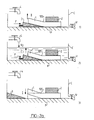
- FIG. 2a the different stages of the education process have been shown by way of non-limiting example.
- Object 1 constituted for example by the above-mentioned rectangular parallelepiped, is placed in a tank C comprising a work surface P and secured to this work surface P by any fixing means 2.
- a force represented by F is applied to the object by means of a wedge 3, which causes at the level of the deformation zone 105, a mechanical stress such that the object is deformed in the zone 105, the object 1 thus being brought into a shape position close to its second shape memory state.
- the stress applied to the object for this purpose can be applied so as to deform the object in its elastic or plastic range, or on the contrary in its range, called deformation plate, super-elastic or rubber, as defined in the Doctoral thesis in Sciences, published by G. GUENIN, INSA Lyon (National Institute of Applied Sciences) in 1979.
- This position is noted II in FIG. 2a 1.
- object 1 is subjected to a lowering of temperature by means for example of a cold source represented by a valve 4.
- the cold source can advantageously consist of a source of liquid nitrogen.
- the lowering of temperature can be carried out either by bringing the object at a temperature below Ms (1a temperature Ms being the temperature at which the martensitic phase begins to form by itself), or at a temperature Ms ⁇ , (the temperature Ms ⁇ being the temperature at which the martensitic phase begins to form form in the presence of constraints), or preferably at a temperature below the temperature Mf (the temperature Mf being the temperature at which the whole of the alloy is transformed into the martensitic phase).
- the gradual warming up to room temperature of the object 1 is obtained by emptying the tank C by opening a valve V and removing the wedge 3. During the warming, the object 1 regains a shape or state of shape memory very close to the initial state noted I.
- the heat treatment capable of bringing the object 1 into the crystallographic phase state of the austenitic type is maintained, the temperature of 800 ° C. being reached, for a period of 1 to 45 minutes.
- the holding time of the above-mentioned heat treatment in fact influences the grain size and, as a function of this holding time, a single-phase crystallographic system with more or less large texture is obtained.
- the stress ⁇ applied to the deformation zone 105 is such that the deformation ⁇ obtained is located in the domain (2) called the deformation plate of the material constituting the object.
- the stress and the deformation applied in the zone 105 correspond to a point located in the field (2) in the vicinity of the field (3), when the object or the zone of deformation is at a temperature lower than the temperature Mf at the end of the martensitic transition or at a temperature higher than the temperature at the start of the martensitic transition, but lower than the temperature Md, the temperature at which the first martensite needle appears in the material when the latter is subjected to a stress.
- the zones 2 on the stress-strain graphs GC, GB correspond, under the aforementioned temperature and stress conditions, to the pseudo-elasticity domains defining the deformation plateau.
- the stress applied for the implementation of the process of education is such that the object is deformed at the level of the deformation zone in its elastic range 1, a slight overflow on plastic zone 2 which can be accepted.
- FIG. 2a in 2a1, 2a2, the application of the stress of the object 1 has been represented by means of a corner.
- the mechanical stress applied to the object 1 can of course be applied during a forming, stamping, or by any mechanical means.
- the object 1 consisting of an ingot for example is secured by means 2 on the work plan P.
- a thermal stress consisting of a temperature variation capable of bringing the object 1 or a deformation zone of it in martensitic crystallographic phase is first imposed in the absence of deformation.
- the tank C is for example filled with liquid nitrogen, the object being covered by it. It is recalled that the shape of object 1 in this state is the initial shape. Then, as shown in FIG.
- an external mechanical stress is imposed on the object 1, in this crystallographic state, at the level of the deformation zone 105 so that the object is deformed in this zone, in its domain called deformation plate, so as to bring the object 1 in a shape position denoted II in FIG. 2b2 close to its second shape memory state.
- this constraint can be applied by means of the wedge 3.
- a state of intermediate form close to the state of initial form is then defined and imposed on the object 1.
- the state of intermediate form is imposed on the object 1 by imposing the limits of subsequent change of form of the object on the corresponding limits of the state of intermediate form.
- the definition and the imposition of the intermediate form state on the object 1 have been represented schematically by a structure or mechanical enclosure 5, closed or not, surrounding the object 1 and capable of authorizing the return of the object 1 to a state of form close to the initial state and thus called state of intermediate form. It is understood that the positioning of the object 1 in the mechanical enclosure 5, the object 1 being released from the securing means 2, can be carried out in the bath of liquid nitrogen, or, the passage of the object of the nitrogen bath in the open air in the mechanical enclosure 5 being made minimum and the thermal inertia of the object 1 being sufficient, this positioning can be carried out outside the liquid nitrogen bath.
- the object 1 on which the shape change limits have been imposed is then subjected to a new thermal stress consisting of heating to ambient temperature in order to bring the object 1 back to the crystallographic phase state of the austenitic type.
- the heating of the object 1 and the maintenance of the latter at the intermediate form make it possible to induce internal stresses authorizing the definition of the state of intermediate form as the first state of shape memory noted I, in FIG. 2b4 where the liquid nitrogen bath was evacuated.
- the return in austenitic state in imposed intermediate form ⁇ i is accompanied by the development of very significant internal stresses as shown schematically in Figure 2c in C.
- the so-called intermediate state of shape is defined and imposed on said object by means of a matrix constituting the mechanical enclosure 5.
- the matrix can for example be made of stainless steel and must have a structure mechanical allowing it to resist the return of the object 1 in an austenitic crystallographic state, which is accompanied by the development of significant internal stresses, which by reaction, are applied to the walls of the matrix.
- the dimensions of the matrix and the position of the object 1 in the matrix are chosen so that the largest dimensions of the object in its state of intermediate shape correspond to the largest internal dimensions.
- the above education process may or may not be repeated over a plurality of cycles. It has, compared to the education process or cycle defined according to FIG. 1a, the advantage of greater precision of deformation and return to the state of shape memory I.
- any combination of the processes of education as defined in connection with FIGS. 1a, 2a, and 1b, 2b with a view to imparting two states of shape memory memorized to a shaped object does not depart from the scope of the present invention.
- the constituent material of the shaped object and consisting either of a sheet, a cylindrical ingot, or a tube for example, is firstly subjected to a treatment at high temperature so as to bring said material to a crystallographic state in which the material is made more malleable.
- the high temperature treatment step consists in bringing said material to a temperature of the order of 500 ° C. or to a temperature making it possible to bring the material into a state capable of suitable shaping. This heating can also preferably be carried out in a neutral atmosphere, under argon pressure.
- the material is then subjected to cooling to a temperature close to room temperature. This rapid cooling can also be carried out by a phenomenon of the water soaking type.
- the soaking type treatment can optionally be replaced by gas jet cooling, whether it is cooling after treatment at high temperature, or after heat treatment capable of bringing the object into a crystallographic phase state of the austenitic type.
- the material thus treated after the abovementioned treatments is therefore in a state where the internal constraints have been removed and in which it has been made more pliable and where it has lost substantially all traces of memory of previous form.
- the material can then be shaped by milling, forming, bar turning, cutting, rolling or the like to obtain its final form of use, which will correspond to its memory state stable at the temperature of use substantially.
- the primary shape of the material can be maintained until the state of zero internal stress of the material is obtained, thereby enabling the reduction of parasitic shape memory effects.
- this operation amounts in fact to carrying out an education of the material having the effect of attenuating the effects of parasitic shape memory by only authorizing a possible subsequent change in shape in a preferred direction, the longitudinal dimension for example of the strip or the rod.
- the material previously treated can consist of a cylindrical tube as represented in FIG. 3a, a cylindrical rod or ingot as represented in FIG. 3b, a sheet metal as shown in Figure 3c1.
- the tube or the rod can be milled so as to comprise respectively one or two lateral slots formed over part of their length.
- the metal sheet shown in FIG. C1 can be cut to size, parts shown in phantom, then rolled by rolling so as to substantially form a tube comprising for example a lateral slit over its entire length, as shown in c2.
- the shaped objects thus described in a nonlimiting manner can then advantageously be subjected to the education process previously described.
- the corner allowing the stress to be applied in the deformation zone can be advantageously replaced either by a cone, male or female, depending on the position or second state of subsequent memory to be obtained, and on the nature of the object to be educate or by any other suitable tool for this purpose.
- metal alloys specially adapted to the implementation of the process and to the manufacture of shaped objects, educated or not, will now be given without limitation.
- the term “metallic alloys” is understood to mean in fact a composition used in the form either of an intermetallic composition or in an alloyed form.
- the aforementioned compositions are compositions of the nickel-titanium group comprising substantially 50% of titanium and 50% of nickel, plus addition compounds such as cobalt, copper, aluminum, making it possible to modify certain parameters of the final material by example the transition temperature Ms and / or the mechanical and electrical properties, nickel-titanium-iron comprising substantially 50% of titanium, 47% of nickel and 3% of iron, zinc-copper-aluminum, comprising substantially 4% ⁇ 0, 5% aluminum, 27 to 29% zinc, the rest of the percentage being copper.
- the percentages indicated are in atomic percent. The aforementioned percentages make it possible, by a judicious choice of the various components, to determine with a good degree of precision the transition temperature Ms of the alloy considered.
- Tests carried out using a composition comprising 4% aluminum, 28% zinc and the copper supplement made it possible to obtain a transition temperature Ms equal to substantially -80 ° C.
- the aforementioned compositions are not limiting, it may be added in particular the ternary copper-aluminum-nickel composition, which allows to obtain shaped objects, educated or not, having better resistance to corrosion and aging.
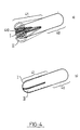
- the element female a or male b electrical contact element comprises a fixed part 40 intended to receive a first electrical circuit element to be connected and an active contact part 41.
- the active part 41 is movable between two positions denoted I, II, ensuring respectively the existence or the rupture of the contact pressure with a second circuit element on which the female part a or even b can be inserted.
- the contact element as shown for example corresponds to the shaped object as described in Figure 3a respectively 3b. It is made of a shape memory material and has been educated in accordance with the method of the invention, so as to have two reversible stored shape memory states, corresponding to positions I, II.
- the education process as defined in accordance with the diagram in FIGS. 1b and 2b may be advantageously preferred, in particular because of the better precision in the degree of return to states form I, II.
- the object 1 constitutes a male or female contact element whose first shape memory state noted I, corresponds to the intermediate shape state substantially and whose second shape memory state noted II, corresponds to the object after deformation applied to the deformation zone, while the internal dimensions of the matrix, or mechanical enclosure 5, are equal to the dimensions of the female or male contact element in its shape memory state I memorized corresponding to the intermediate form state.
- the shape memory material without limitation constituting the contact element belongs to the group nickel-titanium, nickel-aluminum, nickel-titanium-iron, copper-zinc-aluminum, copper-aluminum-nickel. Tests carried out in particular with contact elements, of structure as shown in FIG. 4, have made it possible to ensure a completely satisfactory reproducibility of use by transition between the states of form I and II greater than 100 cycles of use. , for an education consisting of a repetition of the so-called education process, defined in accordance with the diagram of FIGS.
- the method of the invention is particularly remarkable in that, starting from shapes of a shaped object, determined so as to be able to constitute a first state of memory of shape of the object, it allows, by a judicious application of the process to the object or even at a preferential point of the object, an education of this object, conferring on it storage properties of two determined states of form, which in connection with the mechanical structure of the object, its properties physical, its conductivity, in fact allow a function education, here the function of connection-disconnection or even switching.
- the process of the invention differs from that of previous processes in that, in particular, education no longer appears as a structural education linked to the sole overall deformation of the object, but as a punctual education, susceptible in this way to depending on the specific characteristics of the object, to be made functional.
- the contact elements thus obtained can be provided with a conductive protective coating, consisting of a deposit of gold, silver, tin-lead or palladium alloy.
- a conductive protective coating consisting of a deposit of gold, silver, tin-lead or palladium alloy.
- An appropriate underlay may also be provided.
- the electrical contact element according to the invention can be provided at its active contact part 41 with rough edges 410 capable of enabling contact to be made on an insulated conductor by displacement of the insulator.
- the tin-lead coating can indeed be used as an extension of its usual field of use, since there is practically no more problem of friction or wear at the level of each contact element.
- the shaped objects made of a metal alloy with shape memory obtained by implementing the method of the invention are remarkable in that they comprise a first shape memory state corresponding substantially to the initial shape state of the object obtained by the most conventional machining operations, while a second shape memory state, different from the first, is obtained from the latter by local modification of this first shape in at least one point or zone of the structure of this object.
- This modification and the reversible passage from one state of shape memory to another are obtained by modification of the temperature of at least the corresponding zone or zones of the structure of the object.
- the use of such objects is not limited to the field of connectors.
- the aforementioned reversible shape modification of such objects can be used advantageously, in conjunction with other physical parameters thereof, such as conductivity, mechanical strength or the like, in order to confer on them new functions.
- whose essential characteristic is functional autonomy.
- Functional autonomy is understood to mean the absence of the need for direct intervention by an operator with a view to implementing said functions, this intervention being reduced to a single temperature change.
- Such functional autonomy appears particularly suitable for the use of such objects in a hostile environment, in which the presence of an operator is excluded, such as for example in a high intensity ionizing radiation environment.
Landscapes
- Chemical & Material Sciences (AREA)
- Mechanical Engineering (AREA)
- Thermal Sciences (AREA)
- Crystallography & Structural Chemistry (AREA)
- Engineering & Computer Science (AREA)
- Materials Engineering (AREA)
- Physics & Mathematics (AREA)
- Metallurgy (AREA)
- Organic Chemistry (AREA)
- Heat Treatment Of Articles (AREA)
- Heat Treatment Of Sheet Steel (AREA)
- Shaping By String And By Release Of Stress In Plastics And The Like (AREA)
- Connections Effected By Soldering, Adhesion, Or Permanent Deformation (AREA)
- Mechanical Coupling Of Light Guides (AREA)
Description
- La présente invention est relative à un procédé de conditionnement d'un objet constitué en alliage métallique à mémoire de forme pour la mémorisation réversible de deux états de mémoire de forme.
- L'effet de mémoire de forme de certains alliages métalliques est déjà connu de l'état de la technique et a fait l'objet de nombreux travaux à la suite desquels de nombreuses publications en ont montré l'intérêt dans le domaine de la mécanique notamment.
- Plus récemment, la mise en évidence d'un double effet de mémoire réversible pour ce type de matériau permet d'envisager un élargissement de son champ d'application.
- Le double effet de mémoire réversible de ces matériaux a été notamment décrit dans la demande de brevet français 2 413 159 dans laquelle des objets réputés à double effet réversible de mémoire de forme peuvent être réalisés à partir de matériaux pulvérulents compactés à froid puis extrudés à chaud.
- Si de tels objets présentent en effet un double effet de mémoire de forme réversible, celui-ci ne concerne pas des objets façonnés de telle sorte que l'objet, tout au moins ses états de forme mémorisés, ne peuvent être utilisés que dans des applications restreintes dans lesquelles l'état global de changement de forme de l'objet peut être seul utilisé.
- En outre, le double effet de mémoire réversible a été décrit dans la demande de brevet français no 2 279 857. Dans ce même document, le double effet de mémoire de forme réversible est inhérent au procédé de fabrication de l'article lui-même, de sorte que celui-ci, ou tout au moins ses états de forme mémorisés, ne peuvent être utilisés que dans des applications restreintes dans lesquelles l'état global de changement de forme de l'article peut être seul utilisé.
- Enfin, l'article "The remarkable shape-memory alloys = the petals move to the temperature" paru dans JEE, Septembre 1983, p. 89, décrit un objet en forme de fleur dont les pétales, réalisés dans un alliage a mémoire de forme, peuvent se déployer et se refermer lorsque la température varie.
- La présente invention a pour objet de proposer un procédé capable de conférer, à tout objet constitué en un matériau métallique comportant une transition de phase à l'état solide, susceptible d'acquérir une mémorisation de forme, des propriétés de mémoire de forme déterminées, fonctions d'un état de forme mémorisé ou forme initiale de l'objet.
- Un autre objet de la présente invention est la mise en oeuvre d'un procédé capable de conférer, à tout objet constitué en un alliage métallique susceptible d'acquérir une mémorisation de forme, des propriétés de mémorisation de fonctions déterminées, lesquelles sont obtenues à partir d'un état de forme mémorisé de l'objet ou forme initiale de l'objet et de la structure de celui-ci.
- Selon l'invention, un procédé de conditionnement d'un objet constitué en un matériau du type alliage métallique à mémoire de forme pour la mémorisation réversible de deux états de mémoire de forme, procédé consistant à soumettre l'objet, conformé aux formes et dimensions finales constituant un premier état de mémoire de forme, à un traitement thermique capable d'amener l'objet en état de phase cristallographique de type austénitique et à soumettre ledit objet à un refroidissement à une température voisine de la température ambiante, de façon à éviter l'apparition de phase cristallographique parasite, est remarquable en ce qu'il consiste en outre à soumettre ledit objet, en au moins une zone de déformation de celui-ci, à un processus dit d'éducation consistant à imposer audit objet une pluralité de cycles identiques consistant en une série de contraintes thermiques et/ou mécaniques, chaque cycle consistant à appliquer à ladite zone de déformation de l'objet une contrainte mécanique telle que celui-ci soit déformé, dans cette zone, dans son domaine élastique ou superélastique, de manière à amener ledit objet dans une position de forme voisine de son deuxième état de mémoire de forme et à soumettre ledit objet, la contrainte étant maintenue, à un abaissement de température susceptible d'amener ledit objet en état de phase martensitique, puis, la contrainte mécanique étant supprimée, à soumettre ledit objet à un réchauffement progressif pour ramener celui-ci en état de phase cristallographique de type austénitique dans son premier état de mémoire de forme.
- Le procédé de l'invention trouve application notamment dans le domaine de la mécanique, de l'électromécanique et/ou de l'électronique, dans lesquels outre les propriétés mécaniques remarquables de ces matériaux, leurs propriétés électriques peuvent être utilisées.
- Un autre procédé de conditionnement d'un objet constitué en un matériau du type alliage métallique à mémoire de forme pour la mémorisation réversible de deux états de mémoire de forme (I, II), procédé consistant :
- à soumettre l'objet, conformé aux formes et dimensions d'un état de forme initial voisin d'un premier état de mémoire de forme (I), à un traitement thermique capable d'amener ledit objet en état de phase cristallographique de type austénitique,
- à soumettre ledit objet à un refroidissement à une température voisine de la température ambiante, de façon à éviter l'apparition de phase cristallographique parasite, est selon l'invention remarquable en ce qu'il consiste en outre :
- à soumettre ledit objet, en au moins une zone de déformation de celui-ci à un processus dit d'éducation consistant :
- · sur un premier cycle :
- a) à imposer audit objet ou au moins à ladite zone de celui-ci une contrainte thermique consistant en un abaissement de la température capable d'amener celui-ci en état de phase cristallographique martensitique,
- b) à imposer audit objet au niveau de cette zone, dans l'état précité, une contrainte mécanique telle que ledit objet soit déformé, dans cette zone, dans son domaine dit plateau de déformation caoutchoutique, de manière à amener l'objet dans son deuxième état de mémoire de forme,
- c) à définir, pour ledit objet, un état de forme dit intermédiaire (I), voisin dudit état de forme initial, et à imposer audit objet une limite de changement ultérieur de forme correspondant à l'état de forme dit intermédiaire (I),
- d) à soumettre ledit objet, auquel la limite de changement de forme a été imposée, à un réchauffement progressif pour ramener celui-ci en état de phase cristallographique de type austénitique, de manière à induire, dans ladite zone de déformation dudit objet, du fait du réchauffement et du maintien de l'objet à ladite forme intermédiaire (I), des contraintes internes permettant la définition dudit état de forme intermédiaire (I) comme premier état de mémoire de forme,
- · sur une pluralité de cycles identiques, à répéter la succession desdites contraintes thermiques et/ou mécaniques selon les étapes a) et d) entre l'état de mémoire de forme définitif (I), et le deuxième état de mémoire de forme (II).
L'invention sera mieux comprise à la lecture de la description détaillée et à l'observation des dessins ci-après, dans lesquels : - · Les figures 1a et 1b représentent différents schémas synoptiques des étapes du procédé de l'invention,
- · Les figures 2a et 2b représentent en 1, 2, 3 respectivement 4 une illustration de la mise en oeuvre du procédé de l'invention conformément aux schémas des figures 1a et 1b respectivement,
- · La figure 2c représente un diagramme d'efforts appliqués à l'objet au cours du procédé selon l'invention,
- · la figure 3 représente en a, b, c différents modes de réalisation d'un objet susceptible d'être soumis au procédé de l'invention,
- · la figure 4 représenté un objet obtenu suite à la mise en oeuvre du procédé de l'invention.
- Le procédé de conditionnement d'un objet constitué en un matériau du type alliage métallique à mémoire de forme, objet de l'invention, permet la mémorisation réversible de deux états de mémoire de forme. Ce procédé s'applique à tout objet constitué en ce type de matériau. Par tout objet, on entend produit semi-fini ou produit intermédiaire tel que plaques, lingots, fils ou formes analogues sous lesquels les matériaux précités sont disponibles dans le commerce. On entend également par objet, tout objet façonné à l'aide d'opérations classiques de travail de ce type de matériau, permettant d'obtenir des formes complexes fonctionnelles. Le procédé de l'invention sera décrit tout d'abord en liaison avec les figures 1a et 1b.
- L'objet référencé 1 sur les figures précitées, est conformé sensiblement aux formes et dimensions finales susceptibles de constituer un premier état de mémoire de forme préalablement à toute opération de conditionnement proprement dit. L'objet ainsi conformé est tout d'abord soumis à un traitement thermique capable d'amener l'ensemble de l'objet en état de phase cristallographique de type austénitique. Par soucis de simplification, l'objet sur les figures 1a et 1b a été représenté sous forme de lingot parallélépipédique, la forme de parallélépipède rectangle correspondant sensiblement à la forme et à la dimension finales constituant le premier état de mémoire de forme. Consécutivement, à la phase de traitement thermique précitée, l'objet est soumis à un refroidissement à une température voisine de la température ambiante. A titre d'exemple non limitatif, le traitement thermique capable d'amener l'objet en état de phase cristallographique de type austénitique peut être effectué par chauffage de l'objet à une température de l'ordre de 800°C en atmosphère neutre, une atmosphère d'argon par exemple. Le refroidissement peut être effectué de manière non limitative, par un traitement du type trempage à l'eau. En fait le refroidissement est effectué en fonction de l'alliage utilisé de manière à éviter l'apparition gênante de phase cristallographique parasite. L'objet ayant atteint la température ambiante, celui-ci est soumis en au moins une zone de déformation de sa structure à un processus dit d'éducation.
- Sur les figures 1a et 1b, l'application d'une contrainte thermique est représentée symboliquement par le franchissement de la zone cristallographique de transition, représentée par une zone hachurée, entre les états austénitique et martensitique. De même, l'application d'une contrainte mécanique extérieure est représentée par le symbole σ et la représentation de l'objet 1,plié dans un rectangle, l'objet 1 étant ainsi déformé. Par application de la contrainte mécanique externe σ , l'objet 1 étant en état de phase cristallographique austénitique dans le cas de la figure 1a, le même objet 1 ayant subi une contrainte thermique et se trouvant donc dans l'état cristallographique martensitique dans le cas de la figure 1b, l'objet est déformé dans la région de la zone de déformation précitée de manière à amener celui-ci dans un état ou position de forme II voisine de son deuxième état de mémoire de forme. Dans le cas de la figure 1a, l'objet à partir de l'état de forme II est ensuite soumis à une deuxième contrainte thermique le ramenant en un état cristallographique de type austénitique, l'objet 1 reprenant un état de forme voisin de son état de forme initial noté I. Au contraire, dans le cas de la figure 1b, une contrainte mécanique interne obtenue par maintien de l'objet dans un état de forme intermédiaire voisin de l'état de forme initial et constituant le premier état de mémoire de forme de l'objet, est appliquée au cours du retour en phase cristallographique austénitique. Sur la figure 1b, le maintien de l'objet est symbolisé par le contour fermé entourant l'objet 1 déformé en état de mémoire de forme II en état martensitique puis ayant repris sa forme intermédiaire en un état de mémoire de forme noté I, constituant en fait le premier état de mémoire de forme de l'objet.
- Par état de mémoire de forme intermédiaire voisin de l'état de forme initial, on entend le retour à cette forme initiale ou à une forme voisine de celle-ci. Par exemple, dans le cas de pliage d'une tige, la forme dite intermédiaire peut correspondre à un retour à la forme initiale, au niveau de la déformation locale, pouvant atteindre 20 %.
- Bien entendu, et de manière non limitative, chaque cycle ainsi que représenté en figure 1a et 1b, peut ou non être répété de façon à conférer à l'objet un degré de précision de retour au premier état de mémoire de forme noté I suffisant. Dans le cas du processus d'éducation schématisé en figure 1a, celui-ci peut consister en l'application répétitive des étapes correspondantes,constituant un cycle,sur 2 à 20 fois par exemple.
- Le procédé de l'invention notamment dans le cas de la mise en oeuvre d'un processus d'éducation conformément à la figure 1a sera illustré dans sa mise en oeuvre effective au moyen de la figure 2a en 2a1, 2a2, 2a3.
- Sur la figure 2a, les différentes étapes du processus d'éducation ont été représentées à titre d'exemple non limitatif. L'objet 1 constitué par exemple par le parallélépipède rectangle précité, est disposé dans une cuve C comportant un plan de travail P et assujetti sur ce plan de travail P par tout moyen de fixation 2. Un effort représenté par F est appliqué à l'objet au moyen d'un coin 3, lequel provoque au niveau de la zone de déformation 105, une contrainte mécanique telle que l'objet est déformé dans la zone 105, l'objet 1 étant ainsi amené dans une position de forme voisine de son deuxième état de mémoire de forme. La contrainte appliquée à l'objet dans ce but peut être appliquée de manière à déformer l'objet dans son domaine élastique ou plastique, ou au contraire dans son domaine,dit plateau de déformation,super-élastique ou caoutchoutique, tel que défini dans la thèse de Doctorat es Sciences, publiée par G.GUENIN, INSA Lyon (Institut National des Sciences Appliquées) en 1979. Cette position est notée II sur la figure 2a 1. La contrainte étant maintenue, l'objet 1 est soumis à un abaissement de température au moyen par exemple d'une source froide représentée par une vanne 4. La source froide peut consister, de manière avantageuse, en une source d'azote liquide. L'abaissement de température imposé à l'objet 1 dans son état de forme II permet d'amener l'objet en état de phase martensitique ainsi que représenté en figure 2a2.L'abaissement de température peut être effectué soit en amenant l'objet à une température inférieure à Ms (1a température Ms étant la température à laquelle la phase martensitique commence à se former d'elle-même), soit à une température Msσ , (la température Msσ étant la température à laquelle la phase martensitique commence à se former en présence de contraintes), soit de préférence à une température inférieure à la température Mf (la température Mf étant la température à laquelle la totalité de l'alliage est transformée en phase martensitique).
- Ainsi que représenté en figure 2a3, le réchauffement progressif en température ambiante de l'objet 1 est obtenu par vidange de la cuve C par ouverture d'une vanne V et retrait du coin 3. Lors du réchauffement, l'objet 1 retrouve une forme ou état de mémoire de forme très voisine de l'état initial noté I.
- Par exemple, le traitement thermique capable d'amener l'objet 1 en état de phase cristallograhique de type austénitique est maintenu, la température de 800°C étant atteinte, pendant une durée de 1 à 45 minutes. Le temps de maintien du traitement thermique précité influe en fait sur la taille du grain et l'on obtient, en fonction de ce temps de maintien, un système cristallographique monophasé avec texture plus ou moins grosse.
- En outre, ainsi que représenté en figure 2c, la contrainte σ appliquée à la zone de déformation 105 est telle que la déformation ε obtenue soit située dans le domaine (2) dit plateau de déformation du matériau constituant l'objet. De préférence, la contrainte et la déformation appliquée dans la zone 105 correspondent à un point situé dans le domaine (2) au voisinage du domaine (3), lorsque l'objet ou la zone de déformation est à une température inférieure à la température Mf de fin de transition martensitique ou à une température supérieure à la température Ms de début de transition martensitique, mais inférieure à la température Md, température à laquelle la première aiguille de martensite apparaît dans le matériau lorsque celui-ci est soumis à une contrainte. Sur la figure 2c, en B et C les zones 2 sur les graphes contrainte-déformation GC, GB correspondent, dans des conditions de température et de contrainte précitées, aux domaines de pseudo-élasticité définissant le plateau de déformation. Au contraire, dans le cas où l'objet est à une température supérieure à la température Md précédemment définie, ainsi que représenté en figure 2c en A sur le graphe contrainte-déformation GA, la contrainte appliquée pour la mise en oeuvre du processus d'éducation est telle que l'objet soit déformé au niveau de la zone de déformation dans son domaine élastique 1, un léger débordement sur la zone plastique 2 pouvant être accepté.
- Sur la figure 2a, en 2a1, 2a2, on a représenté l'application de la contrainte de l'objet 1 au moyen d'un coin. La contrainte mécanique appliquée à l'objet 1 peut bien entendu être appliquée au cours d'un formage, emboutissage, ou par tout moyen mécanique.
- Le procédé de l'invention sera en outre illustré dans le cas de la mise en oeuvre d'un processus d'éducation, conformément au schéma de la figure 1b, au moyen de la figure 2b, en 2b1, 2b2, 2b3 et 2b4.
- Bien entendu, le matériel nécessaire pour la mise en oeuvre du processus d'éducation conformément à la figure 1a, lequel avait été décrit en liaison avec la figure 2a, peut être utilisé pour la mise en oeuvre du processus d'éducation conformément au schéma de la figure 1b et les éléments de la figure 2b portant les mêmes références que les éléments représentés en figure 2a sont identiques à ces derniers.
- Selon la figure 2b, l'objet 1 constitué en un lingot par exemple est assujetti grâce au moyen 2 sur le plan de travail P. Une contrainte thermique consistant en une variation de température capable d'amener l'objet 1 ou une zone de déformation de celui-ci en phase cristallographique martensitique est en premier lieu imposée en l'absence de déformation. Sur la figure 2b1, la cuve C est par exemple remplie d'azote liquide, l'objet étant recouvert par celui-ci. Il est rappelé que la forme de l'objet 1 dans cet état est la forme initiale. Puis, ainsi que représenté en figure 2b2,une contrainte mécanique extérieure est imposée à l'objet 1, dans cet état cristallographique, au niveau de la zone de déformation 105 de façon que l'objet soit déformé dans cette zone, dans son domaine dit plateau de déformation, de manière à amener l'objet 1 dans une position de forme notée II sur la figure 2b2 voisine de son deuxième état de mémoire de forme. Bien entendu, cette contrainte peut être appliquée au moyen du coin 3. Puis un état de forme intermédiaire voisin de l'état de forme initial est ensuite défini et imposé à l'objet 1. L'état de forme intermédiaire est imposé à l'objet 1 par l'imposition des limites de changement ultérieur de forme de l'objet aux limites correspondantes de l'état de forme intermédiaire. Sur la figure 2b3, la définition et l'imposition de l'état de forme intermédiaire à l'objet 1 ont été représentés schématiquement par une structure ou enceinte mécanique 5, fermée ou non, entourant l'objet 1 et capable d'autoriser le retour de l'objet 1 vers un état de forme voisin de l'état initial et ainsi appelé état de forme intermédiaire. Il est bien entendu que la mise en place de l'objet 1 dans l'enceinte mécanique 5, l'objet 1 étant dégagé des moyens d'assujettisement 2, peut être effectuée dans le bain d'azote liquide, ou, le passage de l'objet du bain d'azote à l'air libre dans l'enceinte mécanique 5 étant rendu minimum et l'inertie thermique de l'objet 1 étant suffisante, cette mise en place peut être effectuée hors du bain d'azote liquide. L'objet 1 auquel les limites de changement de forme ont été imposées est ensuite soumis à une nouvelle contrainte thermique consistant en un réchauffement à température ambiante pour ramener l'objet 1 en état de phase cristallographique de type austénitique. Le réchauffement de l'objet 1 et le maintien de celui-ci à la forme intermédiaire permettent d'induire des contraintes internes autorisant la définition de l'état de forme intermédiaire comme premier état de mémoire de forme noté I, sur la figure 2b4 où le bain d'azote liquide a été évacué. Le retour en état austénitique sous forme intermédiaire imposée εi s'accompagne du développement de contraintes internes or très importantes ainsi que représenté schématiquement en figure 2c en C.
- A titre d'exemple non limitatif, l'état de forme dit intermédiaire, est défini et imposé audit objet au moyen d'une matrice constituant l'enceinte mécanique 5. La matrice peut par exemple être constituée en acier inoxydable et doit présenter une structure mécanique lui permettant de résister au retour de l'objet 1 en état cristallographique austénitique, lequel s'accompagne de développement de contraintes internes importantes, lesquelles par réaction, sont appliquées sur les parois de la matrice. Les dimensions de la matrice et la position de l'objet 1 dans la matrice sont choisis de façon que les plus grandes dimensions de l'objet dans son état de forme intermédiaire correspondent aux dimensions internes les plus grandes.
- Le processus d'éducation précité peut ou non être répété sur une pluralité de cycles. Il présente par rapport au processus d'éducation ou cycle défini selon la figure 1a, l'avantage d'une plus grande précision de déformation et de retour à l'état de mémoire de forme I. Bien entendu, toute combinaison des processus d'éducation tels que définis en liaison avec les figures 1a, 2a, et 1b, 2b en vue de conférer deux états de mémoire de forme mémorisés à un objet façonné ne sort pas du cadre de la présente invention.
- Un exemple de réalisation d'objets façonnés susceptibles, de manière avantageuse,d'être soumis au procédé de conditionnement de l'invention, sera maintenant décrit en liaison avec la figure 3.
- Le matériau constitutif de l'objet façonné et consistant soit en une feuille, un lingot cylindrique, ou un tube par exemple, est tout d'abord soumis à un traitement à haute température de façon à amener ledit matériau à un état cristallographique dans lequel le matériau est rendu plus maléable. L'étape de traitement à haute température consiste à amener ledit matériau à une température de l'ordre de 500°C ou à une température permettant d'amener le matériau dans un état apte à un façonnage convenable. Cet échauffement peut également de préférence être effectué sous atmosphére neutre, sous pression d'argon. Successivement au traitement à haute température, le matériau est ensuite soumis à un refroidissement à une température voisine de la température ambiante. Ce refroidissement rapide peut également être effectué par un phénomène du type trempage à l'eau. En fonction du matériau et de la composition d'alliage métallique de celui-ci, le traitement du type trempage peut éventuellement être remplacé par un refroidissement par jet de gaz, qu'il s'agisse du refroidissement après traitement à haute température, ou après traitement thermique capable d'amener l'objet en état de phase cristallographique de type austénitique. Le matériau ainsi traité après les traitements précités, se trouve donc dans un état où les contraintes internes ont été supprimées et dans lequel il a été rendu plus maléable et où il a perdu sensiblement toute trace de mémoire de forme antérieure. Le matériau peut alors être façonné par fraisage, formage, décolletage, découpe, roulage ou analogues pour obtenir sa forme finale d'utilisation, laquelle correspondra à son état de mémoire stable à la température d'utilisation sensiblement.
- En outre, lors du traitement thermique à haute température précité, la forme première du matériau peut être maintenue jusqu'à ce que l'état de contrainte interne nul du matériau soit obtenu, permettant en celà la réduction des effets de mémoire de forme parasites. En fait, lors de la mise en oeuvre de l'étape précitée pour un matériau en forme de bande ou de tige, cette opération revient en fait à effectuer une éducation du matériau ayant pour effet d'atténuer les effets de mémoire de forme parasites en n'autorisant qu'un changement de forme ultérieur éventuel que selon une direction privilégiée, la dimension longitudinale par exemple de la bande ou de la tige.
- Des exemples de façonnage de l'objet seront maintenant donnés expressément au moyen de la figure 3. Le matériau précédemment traité peut consister en un tube cylindrique ainsi que représenté en figure 3a, une tige ou lingot cylindrique ainsi que représenté en figure 3b, une feuille métallique ainsi que représenté en figure 3c1. Le tube ou la tige peuvent être fraisés de manière à comporter respectivement une ou deux fentes latérales ménagées sur une partie de leur longueur. La feuille métallique représentée en figure c1, peut être découpée à dimension, parties représentées en traits mixtes, puis roulée par roulage de façon à former sensiblement un tube comportant par exemple une fente latérale sur toute sa longueur, ainsi que représenté en c2. Les objets façonnés ainsi décrits de manière non limitative peuvent alors avantageusement être soumis au processus d'éducation précédemment décrit. Le coin permettant d'appliquer la contrainte dans la zone de déformation, peut être avantageusement remplacé soit par un cône, mâle ou femelle, en fonction de la position ou deuxième état de mémoire ultérieur à obtenir, et de la nature de l'objet à éduquer ou par tout autre outil adapté à cet effet.
- Des exemples d'alliages métalliques spécialement adaptés à la mise en oeuvre du procédé et à la fabrication d'objets façonnés, éduqués ou non, seront maintenant donnés de manière non limitative. Par alliages métalliques, on entend en fait composition utilisée sous forme, soit de composition inter-métallique, soit sous forme alliée. De préférence, les compositions précitées sont des compositions du groupe nickel-titane comportant sensiblement 50 % de titane et 50 % de nickel, plus des composés d'addition tels que le cobalt, cuivre, aluminium, permettant de modifier certains paramètres du matériau final par exemple la température de transition Ms et/ou les propriétés mécaniques et électriques, nickel-titane-fer comportant sensiblement 50 % de titane, 47 % de nickel et 3 % de fer, zinc-cuivre-aluminium, comportant sensiblement 4 % ± 0,5 % d'aluminium, 27 à 29 % de zinc, le reste du pourcentage étant constitué par du cuivre. Les pourcentages indiqués s'entendent en pourcentage atomique. Les pourcentages précités permettent par un choix judicieux des différents composants, de déterminer avec un bon degré de précision la température de transition Ms de l'alliage considéré. Des essais effectués à partir d'une composition comprenant 4 % d'aluminium, 28 % de zinc et le complément en cuivre ont permis d'obtenir une température de transition Ms égale à sensiblement -80°C. Bien entendu, les compositions précitées ne sont pas limitatives, il peut être ajouté notamment la composition ternaire cuivre-aluminium-nickel, laquelle permet d'obtenir des objets façonnés, éduqués ou non, présentant une meilleure tenue à la corrosion et au vieillissement.
- Des exemples d'objets obtenus suite à la mise en oeuvre du procédé de l'invention seront maintenant donnés dans l'application très avantageuse à des éléments de contact électrique au moyen de la figure 4. Ainsi que représenté en figure 4, l'élément de contact électrique femelle a ou mâle b comporte une partie fixe 40 destinée à recevoir un premier élément de circuit électrique à connecter et une partie active 41 de contact. La partie active 41 est mobile entre deux positions notées I, II, assurant respectivement l'existence ou la rupture de la pression de contact avec un deuxième élément de circuit sur lequel la partie femelle a ou même b peut être enfichée. L'élément de contact tel que représenté, correspond par exemple à l'objet façonné tel que décrit en figure 3a respectivement 3b. Il est constitué en un matériau à mémoire de forme et a été éduqué conformément au procédé de l'invention, de façon à posséder deux états de mémoire de forme mémorisés réversibles, correspondants aux positions I, II.
- Dans le cas particulier de la mise en oeuvre du procédé de l'invention pour la réalisation d'éléments de contact électrique, le processus d'éducation tel que défini conformément au schéma des figures 1b et 2b pourra être avantageusement préféré en raison notamment de la meilleure précision dans le degré de retour aux états de forme I, II. En outre, et de manière préférentielle, l'objet 1 constitue un élément de contact mâle ou femelle dont le premier état de mémoire de forme noté I, correspond à l'état de forme intermédiaire sensiblement et dont le deuxième état de mémoire de forme noté II, correspond à l'objet après déformation appliquée à la zone de déformation, alors que les dimensions internes de la matrice, ou enceinte mécanique 5, sont égales aux dimensions de l'élément de contact femelle ou mâle dans son état de mémoire de forme I mémorisé correspondant à l'état de forme intermédiaire.
- Ce processus d'éducation apparaît donc particulièrement adapté au domaine de la connectique, la matrice pouvant être constituée soit par une copie de l'élément de contact femelle ou mâle correspondant, soit par cet élément de contact lui-même. Bien entendu, le matériau à mémoire de forme, de manière non limitative constituant l'élément de contact appartient au groupe nickel-titane, nickel-aluminium, nickel-titane-fer, cuivre-zinc-aluminium, cuivre-aluminium-nickel. Des essais effectués notamment avec des éléments de contact, de structure telle que représentée en figure 4, ont permis d'assurer une reproductibilité d'utilisation tout à fait satisfaisante par transition entre les états de forme I et II supérieure à 100 cycles d'utilisation, pour une éducation consistant en une répétition du processus dit d'éducation, défini conformément au schéma des figures 1a et 2a, ne dépassant pas quelques unités. Ainsi, le procédé de l'invention est particulièrement remarquable en ce que, à partir de formes d'un objet façonné, déterminées de façon à pouvoir constituer un premier état de mémoire de forme de l'objet, il permet, par une application judicieuse du procédé à l'objet ou même en un point préférentiel de l'objet, une éducation de cet objet, lui conférant des propriétés de mémorisation de deux états de forme déterminés, lesquelles en liaison avec la structure mécanique de l'objet, ses propriétés physiques, sa conductibilité, permettent en fait une éducation de fonction, ici la fonction de connexion-déconnexion ou même de commutation. Le procédé de l'invention se distingue en celà des procédés antérieurs en ce que,notamment, l'éducation apparaît non plus comme une éducation structurelle liée à la seule déformation globale de l'objet, mais en une éducation ponctuelle, susceptible en celà en fonction des caractéristiques propres de l'objet, d'être rendue fonctionnelle.
- On comprendra en particulier, que dans l'application précédemment décrite à un élément de contact électrique, la seule commande d'abaissement de température de l'objet en deçà de la température de transition Ms du matériau le constituant, permet immédiatement le passage en position II ou deuxième position de mémoire de forme, position autorisant, le contact étant rompu, toute déconnexion aisée. Le retour de l'élément de contact a une température située au delà de la température Ms permet alors le retour à la position de mémoire de forme initiale, ou première position. On notera enfin, que les éléments de contact femelle a, mâle b, peuvent ou non être éduqués de manière dite complémentée. Par état complémenté, on entend dans l'exemple précité, variation de positions spatiales opposées des parties mobiles des éléments femelle a ou mâle b, pour un même abaissement ou une même augmentation de température, en delà ou au-delà de la température de transition.
- En outre, les éléments de contact ainsi obtenus peuvent être munis d'un revêtement protecteur conducteur, consistant en un dépôt d'or, d'argent, d'étain-plomb ou d'alliage de palladium. Une sous-couche appropriée peut en outre être prévue. Enfin, l'élément de contact électrique selon l'invention, peut être muni au niveau de sa partie active de contact 41, d'aspérités 410 susceptibles de permettre la réalisation d'un contact sur un conducteur isolé par déplacement d'isolant. Le revêtement d'étain-plomb peut en effet être utilisé en élargissement de son champ d'utilisation habituel, puisqu'il n'existe pratiquement plus de problème de frottement ni d'usure au niveau de chaque élément de contact.
- Les objets façonnés constitués en un alliage métallique à mémoire de forme obtenus par la mise en oeuvre du procédé de l'invention sont remarquables en ce qu'ils comportent un premier état de mémoire de forme correspondant sensiblement à l'état de forme initial de l'objet obtenu par les opérations d'usinage les plus classiques, alors qu'un deuxième état de mémoire de forme, différent du premier, est obtenu à partir de ce dernier par modification locale de cette première forme en au moins un point ou zone de la structure de cet objet. Cette modification et le passage réversible d'un état de mémoire de forme à l'autre sont obtenus par modification de la température d'au moins la ou les zones correspondantes de la structure de l'objet. L'utilisation de tels objets n'est pas limitée au domaine de la connectique. En particulier, la modifacation de forme réversible précitée de tels objets, peut être utilisée avantageusement, en liaison avec d'autres paramètres physiques de ceux-ci, tels que conductibilité, résistance mécanique ou autres, afin de conférer à ceux-ci de nouvelles fonctions dont la caractéristique essentielle est l'autonomie fonctionnelle. Par autonomie fonctionnelle, on entend l'absence de nécessité d'intervention directe d'un opérateur en vue de la mise en oeuvre desdites fonctions, cette intervention se résumant à une seule modification de température. Une telle autonomie fonctionnelle apparaît particulièrement adaptée pour l'utilisation de tels objets en environnement hostile, dans lequel la présence d'un opérateur est exclue comme par exemple en environnement de rayonnement ionisant de grande intensité.
Claims (11)
- Procédé de conditionnement d'un objet constitué en un matériau du type alliage métallique à mémoire de forme pour la mémorisation réversible de deux états de mémoire de forme, procédé consistant :- à soumettre l'objet, conformé aux formes et dimensions finales constituant un premier état de mémoire de forme, à un traitement thermique capable d'amener ledit objet en état de phase cristallographique de type austénitique,- à soumettre ledit objet à un refroidissement à une température voisine de la température ambiante, de façon à éviter l'apparition de phase cristallographique parasite,
caractérisé en ce qu'il consiste en outre :
- à soumettre ledit objet, en au moins une zone de déformation de celui-ci, à un processus dit d'éducation consistant à imposer audit objet une pluralité de cycles identiques consistant en une série de contraintes thermiques et/ou mécaniques, chaque cycle consistant à appliquer à ladite zone de déformation de l'objet une contrainte mécanique telle que celui-ci soit déformé, dans cette zone, dans son domaine élastique ou superélastique, de manière à amener ledit objet dans une position de forme voisine de son deuxième état de mémoire de forme et à soumettre ledit objet, la contrainte étant maintenue, à un abaissement de température susceptible d'amener ledit objet en état de phase martensitique, puis, la contrainte mécanique étant supprimée, à soumettre ledit objet à un réchauffement progressif pour ramener celui-ci en état de phase cristallographique de type austénitique dans son premier état de mémoire de forme. - Procédé de conditionnement d'un objet constitué en un matériau du type alliage métallique à mémoire de forme pour la mémorisation réversible de deux états de mémoire de forme (I, II), procédé consistant :- à soumettre l'objet, conformé aux formes et dimensions d'un état de forme initial voisin d'un premier état de mémoire de forme (I), à un traitement thermique capable d'amener ledit objet en état de phase cristallographique de type austénitique,- à soumettre ledit objet à un refroidissement à une température voisine de la température ambiante, de façon à éviter l'apparition de phase cristallographique parasite, caractérisé en ce qu'il consiste en outre :- à soumettre ledit objet, en au moins une zone de déformation de celui-ci à un processus dit d'éducation consistant :· sur un premier cycle :a) à imposer audit objet ou au moins à ladite zone de celui-ci une contrainte thermique consistant en un abaissement de la température capable d'amener celui-ci en état de phase cristallographique martensitique,b) à imposer audit objet au niveau de cette zone, dans l'état précité, une contrainte mécanique telle que ledit objet soit déformé, dans cette zone, dans son domaine dit plateau de déformation caoutchoutique, de manière à amener l'objet dans son deuxième état de mémoire de forme,c) à définir, pour ledit objet, un état de forme dit intermédiaire (I), voisin dudit état de forme initial, et à imposer audit objet une limite de changement ultérieur de forme correspondant à l'état de forme dit intermédiaire (I),d) à soumettre ledit objet, auquel la limite de changement de forme a été imposée, à un réchauffement progressif pour ramener celui-ci en état de phase cristallographique de type austénitique, de manière à induire, dans ladite zone de déformation dudit objet, du fait du réchauffement et du maintien de l'objet à ladite forme intermédiaire (I), des contraintes internes permettant la définition dudit état de forme intermédiaire (I) comme premier état de mémoire de forme,· sur une pluralité de cycles identiques, à répéter la succession desdites contraintes thermiques et/ou mécaniques selon les étapes a) et d) entre l'état de mémoire de forme définitif (I), et le deuxième état de mémoire de forme (II).
- Procédé selon la revendication 2, caractérisé en ce que l'état de forme dit intermédiaire est défini et imposé audit objet au moyen d'une matrice, les dimensions de la matrice étant choisies et l'objet étant placé dans ladite matrice de façon que les plus grandes dimensions de l'objet dans son état de forme intermédiaire correspondent aux dimensions internes les plus grandes de la matrice.
- Procédé selon la revendication 3, caractérisé en ce que dans le cas de sa mise en oeuvre pour la réalisation d'un élément de contact, l'objet constituant un élément de contact mâle ou femelle dont le premier état de mémoire de forme correspond à l'état de forme intermédiaire et dont le deuxième état de mémoire de forme correspond à l'objet après déformation appliquée à la zone de déformation, les dimensions internes de la matrice sont choisies égales aux dimensions de l'élément de contact femelle ou mâle correspondant.
- Procédé selon l'une des revendications 1 à 4, caractérisé en ce que dans le cas d'objets façonnés, ledit procédé consiste, préalablement à l'étape de traitement thermique capable d'amener ledit objet en état de phase cristallographique de type austénitique, à soumettre le matériau constitutif de l'objet à un traitement à haute température de façon à amener ledit matériau à un état cristallographique, dans lequel les contraintes internes sont supprimées.
- Procédé selon la revendication 5, caractérisé en ce que, lors du traitement thermique à haute température, la forme première du matériau est maintenue jusqu'à ce que l'état de contrainte interne nul du matériau soit obtenu permettant en cela la réduction des effets de mémoire de forme parasites.
- Procédé selon la revendication 1 ou 2, caractérisé en ce que lors de l'étape pendant laquelle l'objet est soumis à un traitement thermique capable d'amener celui-ci en phase austénitique, l'objet est amené à une température voisine de 800°C et maintenu à cette température entre 1 et 45 minutes.
- Procédé selon la revendication 1 ou 2, caractérisé en ce que les étapes consistant à soumettre l'objet à un refroidissement à une température voisine de la température ambiante est effectué par un traitement du type trempage.
- Procédé selon l'une des revendications précédentes, caractérisé en ce que, pendant le processus dit d'éducation, l'application de ladite contrainte mécanique est effectuée par déformation de l'objet.
- Procédé selon l'une des revendications précédentes, caractérisé en ce que, pendant le processus dit d'éducation, ledit abaissement de température est effectué de manière à amener ledit objet à une température inférieure à sa température Mf de fin de transition martensitique, ladite variation de température étant susceptible d'amener au moins la ou les zones de déformation à l'état martensitique.
- Procédé selon l'une des revendications précédentes, caractérisé en ce que l'objet est constitué en un matériau du type alliage métallique à mémoire de forme, du groupe nickel-titane, nickel-titane-fer, cuivre-zinc-aluminium, cuivre-aluminium-nickel, nickel-aluminium.
Applications Claiming Priority (2)
| Application Number | Priority Date | Filing Date | Title |
|---|---|---|---|
| FR8405815A FR2563055A1 (fr) | 1984-04-12 | 1984-04-12 | Procede de realisation de connecteur |
| FR8405815 | 1984-04-12 |
Publications (3)
| Publication Number | Publication Date |
|---|---|
| EP0161952A2 EP0161952A2 (fr) | 1985-11-21 |
| EP0161952A3 EP0161952A3 (en) | 1985-12-18 |
| EP0161952B1 true EP0161952B1 (fr) | 1991-05-15 |
Family
ID=9303125
Family Applications (1)
| Application Number | Title | Priority Date | Filing Date |
|---|---|---|---|
| EP85400523A Expired - Lifetime EP0161952B1 (fr) | 1984-04-12 | 1985-03-19 | Procédé de conditionnement d'un object en alliage métallique à mémoire de forme à deux états de mémoire de forme réversibles |
Country Status (6)
| Country | Link |
|---|---|
| US (1) | US4753689A (fr) |
| EP (1) | EP0161952B1 (fr) |
| JP (1) | JPS61270359A (fr) |
| CA (1) | CA1251268A (fr) |
| DE (1) | DE3582819D1 (fr) |
| FR (1) | FR2563055A1 (fr) |
Families Citing this family (31)
| Publication number | Priority date | Publication date | Assignee | Title |
|---|---|---|---|---|
| FR2590048B1 (fr) * | 1985-07-19 | 1992-05-15 | Souriau & Cie | Dispositif de declenchement mecanique sequentiel |
| FR2594254B1 (fr) * | 1986-01-30 | 1988-02-26 | Souriau & Cie | Element a memoire de forme pour raccord de tresse sur connecteur. |
| FR2602373B1 (fr) * | 1986-08-04 | 1990-06-01 | Souriau & Cie | Contact electrique pour connecteur multicontacts et connecteur comportant de tels contacts electriques |
| FR2617187B1 (fr) * | 1987-06-24 | 1989-10-20 | Cezus Co Europ Zirconium | Procede d'amelioration de la ductilite d'un produit en alliage a transformation martensitique et son utilisation |
| FR2618163B1 (fr) * | 1987-07-15 | 1992-04-30 | Trefimetaux | Procede d'education d'un objet en alliage a memoire de forme, permettant d'assurer la precision et la stabilite de l'effet memoire reversible. |
| FR2620779B1 (fr) * | 1987-09-23 | 1990-01-26 | Souriau & Cie | Element d'assemblage demontable pour assemblage mecanique |
| US4881981A (en) * | 1988-04-20 | 1989-11-21 | Johnson Service Company | Method for producing a shape memory alloy member having specific physical and mechanical properties |
| EP0382109B1 (fr) * | 1989-02-08 | 1993-12-08 | Nivarox-FAR S.A. | Procédé de conditionnement d'une pièce en alliage métallique à mémoire de forme présentant deux états de mémoire de forme réversibles |
| FR2643086B1 (fr) * | 1989-02-10 | 1991-05-24 | Nivarox Sa | Procede de conditionnement d'une piece en alliage metallique a memoire de forme presentant deux etats de memoire de forme reversibles |
| CH677677A5 (fr) * | 1989-02-08 | 1991-06-14 | Nivarox Sa | |
| JPH07103457B2 (ja) * | 1989-02-10 | 1995-11-08 | トミー株式会社 | 形状記憶合金製矯正ワイヤーの形態付与方法 |
| FR2663470A1 (fr) * | 1990-06-18 | 1991-12-20 | Souriau & Cie | Element de raccordement d'un cable coaxial a des broches de contact. |
| FR2664836B1 (fr) * | 1990-07-20 | 1992-11-13 | Imago | Machine de traitement thermo-mecanique pour elements en alliages a memoire de forme. |
| US5133721A (en) * | 1991-03-19 | 1992-07-28 | The United States Of America As Represented By The Administrator Of The National Aeronautics And Space Administration | Device for removing foreign objects from anatomic organs |
| US5203931A (en) * | 1991-09-20 | 1993-04-20 | University Of Missouri | Electrodeposition of indium-thallium shape memory alloys |
| US6123715A (en) * | 1994-07-08 | 2000-09-26 | Amplatz; Curtis | Method of forming medical devices; intravascular occlusion devices |
| US5641364A (en) * | 1994-10-28 | 1997-06-24 | The Furukawa Electric Co., Ltd. | Method of manufacturing high-temperature shape memory alloys |
| US5624508A (en) * | 1995-05-02 | 1997-04-29 | Flomenblit; Josef | Manufacture of a two-way shape memory alloy and device |
| US5882444A (en) * | 1995-05-02 | 1999-03-16 | Litana Ltd. | Manufacture of two-way shape memory devices |
| FR2756767A1 (fr) * | 1996-12-06 | 1998-06-12 | Andromis Sa | Dispositif de prehension en materiau a memoire de forme et procede de realisation |
| FR2756768A1 (fr) * | 1996-12-06 | 1998-06-12 | Andromis Sa | Dispositif de prehension en materiau a memoire de forme et procede de realisation |
| US6149742A (en) * | 1998-05-26 | 2000-11-21 | Lockheed Martin Corporation | Process for conditioning shape memory alloys |
| FR2797275B1 (fr) * | 1999-08-04 | 2001-11-23 | Mat Inov | Procede pour memoriser deux etats geometriques d'un produit realise dans un alliage a memoire de forme et applications de ce procede a des produits dans le domaine medical, dentaire, veterinaire ou autres |
| DE10108956A1 (de) * | 2001-02-23 | 2002-09-12 | Siemens Ag | Montageelement zum Verbinden zweier Gegenstände, insbesondere zweier Geräteteile |
| GB0110647D0 (en) * | 2001-05-01 | 2001-06-20 | Accademie Friulane S R L | Forming a shape memory alloy component |
| US6797083B2 (en) * | 2001-06-11 | 2004-09-28 | Ev3 Inc. | Method of training nitinol wire |
| WO2004092581A1 (fr) * | 2003-04-15 | 2004-10-28 | Board Of Trustees Operating Michigan State University | Actionneur de memoire de forme d'un film mince contracte utilisant des substrats polymeres |
| US7761974B2 (en) * | 2005-01-19 | 2010-07-27 | Gm Global Technology Operations, Inc. | Reconfigurable fixture device and methods of use |
| WO2008070130A1 (fr) * | 2006-12-04 | 2008-06-12 | Cook Incorporated | Procédé pour charger un dispositif médical dans un système d'administration |
| EP2268234B1 (fr) * | 2008-04-23 | 2012-02-29 | Cook Medical Technologies LLC | Procédé de chargement d'un dispositif médical dans un système d'administration |
| US8409372B1 (en) | 2010-09-02 | 2013-04-02 | The United States of America as Represented by the Administraton of National Aeronautics and Space Administration | Thermomechanical methodology for stabilizing shape memory alloy (SMA) response |
Citations (1)
| Publication number | Priority date | Publication date | Assignee | Title |
|---|---|---|---|---|
| US4205293A (en) * | 1977-05-06 | 1980-05-27 | Bbc Brown Boveri & Company Limited | Thermoelectric switch |
Family Cites Families (14)
| Publication number | Priority date | Publication date | Assignee | Title |
|---|---|---|---|---|
| BE755271A (fr) * | 1969-08-25 | 1971-02-25 | Raychem Corp | Raccord metallique pouvant reprendre sa forme a la chaleur |
| US3740839A (en) * | 1971-06-29 | 1973-06-26 | Raychem Corp | Cryogenic connection method and means |
| GB1425465A (en) * | 1972-05-04 | 1976-02-18 | Raychem Ltd | Method of making electrical connections |
| DE2406236C2 (de) * | 1974-02-09 | 1982-05-06 | Kabel- und Metallwerke Gutehoffnungshütte AG, 3000 Hannover | Verbindungselement für koaxiale Paare von Nachrichtenkabeln |
| JPS5818427B2 (ja) * | 1974-07-05 | 1983-04-13 | 大阪大学長 | 繰り返し形状記憶性を有する金属物品の製法 |
| US4036669A (en) * | 1975-02-18 | 1977-07-19 | Raychem Corporation | Mechanical preconditioning method |
| MX4156E (es) * | 1975-02-18 | 1982-01-13 | Raychem Corp | Un metodo para expandir o extender el lazo de histeresis de aleaciones por ejemplo aleaciones de cobre o zinc |
| GB1579734A (en) * | 1977-03-11 | 1980-11-26 | Raychem Ltd | Methods of making electrical connections and connectors for use therein |
| US4435229A (en) * | 1979-09-25 | 1984-03-06 | Johnson Alfred D | Method of preparing a two-way shape memory alloy |
| US4487465A (en) * | 1981-12-07 | 1984-12-11 | Raychem Corporation | Heat recoverable connecting device |
| US4497527A (en) * | 1982-09-30 | 1985-02-05 | Raychem Corporation | Supplementary force heat-recoverable connecting device |
| US4462651A (en) * | 1982-12-10 | 1984-07-31 | Raychem Corporation | Reusable heat-recoverable connecting device |
| JPS59146175A (ja) * | 1983-02-10 | 1984-08-21 | 株式会社日立製作所 | 電気接続装置 |
| JPS59179767A (ja) * | 1983-03-30 | 1984-10-12 | Sumitomo Special Metals Co Ltd | 可逆形状記憶素子の製造方法 |
-
1984
- 1984-04-12 FR FR8405815A patent/FR2563055A1/fr active Pending
-
1985
- 1985-03-19 DE DE8585400523T patent/DE3582819D1/de not_active Expired - Fee Related
- 1985-03-19 EP EP85400523A patent/EP0161952B1/fr not_active Expired - Lifetime
-
1986
- 1986-03-13 US US06/839,181 patent/US4753689A/en not_active Expired - Fee Related
- 1986-03-18 CA CA000504416A patent/CA1251268A/fr not_active Expired
- 1986-03-19 JP JP61061944A patent/JPS61270359A/ja active Pending
Patent Citations (1)
| Publication number | Priority date | Publication date | Assignee | Title |
|---|---|---|---|---|
| US4205293A (en) * | 1977-05-06 | 1980-05-27 | Bbc Brown Boveri & Company Limited | Thermoelectric switch |
Non-Patent Citations (2)
| Title |
|---|
| " The remarkable shape-memory alloys ", JEE, September 1983, p. 89-93 * |
| Petit Robert p. 748, 1490, 2111 * |
Also Published As
| Publication number | Publication date |
|---|---|
| CA1251268A (fr) | 1989-03-14 |
| EP0161952A3 (en) | 1985-12-18 |
| JPS61270359A (ja) | 1986-11-29 |
| EP0161952A2 (fr) | 1985-11-21 |
| DE3582819D1 (de) | 1991-06-20 |
| FR2563055A1 (fr) | 1985-10-18 |
| US4753689A (en) | 1988-06-28 |
Similar Documents
| Publication | Publication Date | Title |
|---|---|---|
| EP0161952A2 (fr) | Procédé de conditionnement d'un object en alliage métallique à mémoire de forme à deux états de mémoire de forme réversibles | |
| Park et al. | Effect of laser shock peening without coating on fretting corrosion of copper contacts | |
| JPH0433862B2 (fr) | ||
| EP2400354A1 (fr) | Pieds de cadran de pièce d'horlogerie | |
| EP0864664A1 (fr) | Procédé de fabrication d'une pièce superélastique en alliage de nickel et de titane | |
| EP2608296A1 (fr) | Collecteur de courant en métal amorphe | |
| EP0296942B1 (fr) | Procédé de brasage au four sous atmosphère raréfiée ou contrôlée de deux pièces | |
| EP0578518B1 (fr) | Procédé de formation d'un insert sur une pièce à revêtir en acier ou en alliage de titane | |
| EP0196256B1 (fr) | Borne de contact électrique thermo-enfichable sur une carte de circuit imprimé et connecteur comportant de telles bornes | |
| EP0197820A1 (fr) | Connecteur électrique à élément de contact en matériau à mémoire de forme | |
| JP6328410B2 (ja) | アルミ合金部材の製造方法 | |
| WO2005035817A2 (fr) | Procede d'elaboration d'un produit plat en alliage de zirconium, produit plat ainsi obtenu et grille de reacteur de centrale nucleaire realisee a partir de ce produit plat | |
| CA1296788C (fr) | Raccord pour connexion de zones de contact electrique en materiau a memoire de forme | |
| Zhang et al. | Understanding indentation-induced two-way shape memory effect | |
| Sundar et al. | Laser removal of TiN from coated carbide substrate | |
| EP0382109B1 (fr) | Procédé de conditionnement d'une pièce en alliage métallique à mémoire de forme présentant deux états de mémoire de forme réversibles | |
| WO2013014369A1 (fr) | Procede d'assemblage d'une coque titane et d'une coque alliage resistant au feu titane | |
| EP0438338B1 (fr) | Procédé d'obtention d'un produit à partir de poudres préalliées et produit obtenu à partir dudit procédé | |
| FI66206C (fi) | Produkt som aer reversibelt i vaerme och foerfarande foer dess framstaellning | |
| Kayaba et al. | Frictional properties of surface films in air and in high vacuum | |
| CH677677A5 (fr) | ||
| Sitnikov et al. | Study of the Effect of Tensile Stress During Electric Pulse Treatment of Amorphous Rapidly Hardened Ti50Ni25Cu25 Alloys on Crystal Structure Formation | |
| FR2579380A1 (fr) | Borne de contact electrique thermo-enfichable sur une carte de circuit imprime et connecteur comportant de telles bornes | |
| Srećković et al. | Interaction of lasers of various types with alloys based on Ni and Ti | |
| FR2609916A1 (fr) | Procede de forgeage sous enveloppe et par matricage a chaud d'un materiau peu ductile et tres resistant en etat superplastique |
Legal Events
| Date | Code | Title | Description |
|---|---|---|---|
| PUAI | Public reference made under article 153(3) epc to a published international application that has entered the european phase |
Free format text: ORIGINAL CODE: 0009012 |
|
| PUAL | Search report despatched |
Free format text: ORIGINAL CODE: 0009013 |
|
| AK | Designated contracting states |
Designated state(s): BE CH DE FR GB IT LI LU NL SE |
|
| AK | Designated contracting states |
Designated state(s): BE CH DE FR GB IT LI LU NL SE |
|
| 17P | Request for examination filed |
Effective date: 19860113 |
|
| 17Q | First examination report despatched |
Effective date: 19861111 |
|
| GRAA | (expected) grant |
Free format text: ORIGINAL CODE: 0009210 |
|
| AK | Designated contracting states |
Kind code of ref document: B1 Designated state(s): BE CH DE FR GB IT LI LU NL SE |
|
| GBT | Gb: translation of ep patent filed (gb section 77(6)(a)/1977) | ||
| ITF | It: translation for a ep patent filed | ||
| REF | Corresponds to: |
Ref document number: 3582819 Country of ref document: DE Date of ref document: 19910620 |
|
| PLBE | No opposition filed within time limit |
Free format text: ORIGINAL CODE: 0009261 |
|
| STAA | Information on the status of an ep patent application or granted ep patent |
Free format text: STATUS: NO OPPOSITION FILED WITHIN TIME LIMIT |
|
| 26N | No opposition filed | ||
| PGFP | Annual fee paid to national office [announced via postgrant information from national office to epo] |
Ref country code: FR Payment date: 19930226 Year of fee payment: 9 |
|
| PGFP | Annual fee paid to national office [announced via postgrant information from national office to epo] |
Ref country code: SE Payment date: 19930312 Year of fee payment: 9 Ref country code: GB Payment date: 19930312 Year of fee payment: 9 |
|
| PGFP | Annual fee paid to national office [announced via postgrant information from national office to epo] |
Ref country code: NL Payment date: 19930331 Year of fee payment: 9 |
|
| PGFP | Annual fee paid to national office [announced via postgrant information from national office to epo] |
Ref country code: CH Payment date: 19930419 Year of fee payment: 9 |
|
| PGFP | Annual fee paid to national office [announced via postgrant information from national office to epo] |
Ref country code: DE Payment date: 19930423 Year of fee payment: 9 |
|
| PGFP | Annual fee paid to national office [announced via postgrant information from national office to epo] |
Ref country code: LU Payment date: 19930503 Year of fee payment: 9 |
|
| PGFP | Annual fee paid to national office [announced via postgrant information from national office to epo] |
Ref country code: BE Payment date: 19930513 Year of fee payment: 9 |
|
| EPTA | Lu: last paid annual fee | ||
| PG25 | Lapsed in a contracting state [announced via postgrant information from national office to epo] |
Ref country code: LU Free format text: LAPSE BECAUSE OF NON-PAYMENT OF DUE FEES Effective date: 19940319 Ref country code: GB Effective date: 19940319 |
|
| PG25 | Lapsed in a contracting state [announced via postgrant information from national office to epo] |
Ref country code: SE Free format text: LAPSE BECAUSE OF NON-PAYMENT OF DUE FEES Effective date: 19940320 |
|
| PG25 | Lapsed in a contracting state [announced via postgrant information from national office to epo] |
Ref country code: LI Effective date: 19940331 Ref country code: CH Effective date: 19940331 Ref country code: BE Effective date: 19940331 |
|
| BERE | Be: lapsed |
Owner name: SOURIAU ET CIE Effective date: 19940331 |
|
| PG25 | Lapsed in a contracting state [announced via postgrant information from national office to epo] |
Ref country code: NL Effective date: 19941001 |
|
| GBPC | Gb: european patent ceased through non-payment of renewal fee |
Effective date: 19940319 |
|
| NLV4 | Nl: lapsed or anulled due to non-payment of the annual fee | ||
| PG25 | Lapsed in a contracting state [announced via postgrant information from national office to epo] |
Ref country code: FR Effective date: 19941130 |
|
| REG | Reference to a national code |
Ref country code: CH Ref legal event code: PL |
|
| PG25 | Lapsed in a contracting state [announced via postgrant information from national office to epo] |
Ref country code: DE Effective date: 19941201 |
|
| REG | Reference to a national code |
Ref country code: FR Ref legal event code: ST |
|
| EUG | Se: european patent has lapsed |
Ref document number: 85400523.8 Effective date: 19941010 |