EP0161673A2 - Method for controlling the operating condition of a polarographic membrane covered probe - Google Patents
Method for controlling the operating condition of a polarographic membrane covered probe Download PDFInfo
- Publication number
- EP0161673A2 EP0161673A2 EP85105949A EP85105949A EP0161673A2 EP 0161673 A2 EP0161673 A2 EP 0161673A2 EP 85105949 A EP85105949 A EP 85105949A EP 85105949 A EP85105949 A EP 85105949A EP 0161673 A2 EP0161673 A2 EP 0161673A2
- Authority
- EP
- European Patent Office
- Prior art keywords
- electrode
- potential difference
- sensor
- counter
- potential
- Prior art date
- Legal status (The legal status is an assumption and is not a legal conclusion. Google has not performed a legal analysis and makes no representation as to the accuracy of the status listed.)
- Granted
Links
- 238000000034 method Methods 0.000 title claims description 17
- 239000000523 sample Substances 0.000 title abstract 4
- 239000012528 membrane Substances 0.000 title description 5
- 238000005259 measurement Methods 0.000 claims description 6
- 238000001514 detection method Methods 0.000 claims description 2
- 239000008151 electrolyte solution Substances 0.000 claims description 2
- 230000001960 triggered effect Effects 0.000 claims 1
- 239000003792 electrolyte Substances 0.000 description 10
- 239000000243 solution Substances 0.000 description 6
- VEXZGXHMUGYJMC-UHFFFAOYSA-M Chloride anion Chemical compound [Cl-] VEXZGXHMUGYJMC-UHFFFAOYSA-M 0.000 description 5
- 229910021607 Silver chloride Inorganic materials 0.000 description 4
- QVGXLLKOCUKJST-UHFFFAOYSA-N atomic oxygen Chemical compound [O] QVGXLLKOCUKJST-UHFFFAOYSA-N 0.000 description 4
- 239000001301 oxygen Substances 0.000 description 4
- 229910052760 oxygen Inorganic materials 0.000 description 4
- HKZLPVFGJNLROG-UHFFFAOYSA-M silver monochloride Chemical compound [Cl-].[Ag+] HKZLPVFGJNLROG-UHFFFAOYSA-M 0.000 description 4
- 238000009792 diffusion process Methods 0.000 description 3
- 239000007789 gas Substances 0.000 description 3
- PCHJSUWPFVWCPO-UHFFFAOYSA-N gold Chemical compound [Au] PCHJSUWPFVWCPO-UHFFFAOYSA-N 0.000 description 3
- 229910052737 gold Inorganic materials 0.000 description 3
- 239000010931 gold Substances 0.000 description 3
- WCUXLLCKKVVCTQ-UHFFFAOYSA-M Potassium chloride Chemical compound [Cl-].[K+] WCUXLLCKKVVCTQ-UHFFFAOYSA-M 0.000 description 2
- BQCADISMDOOEFD-UHFFFAOYSA-N Silver Chemical compound [Ag] BQCADISMDOOEFD-UHFFFAOYSA-N 0.000 description 2
- 230000007423 decrease Effects 0.000 description 2
- 150000004820 halides Chemical class 0.000 description 2
- 230000010287 polarization Effects 0.000 description 2
- 238000012545 processing Methods 0.000 description 2
- 230000001105 regulatory effect Effects 0.000 description 2
- 229910052709 silver Inorganic materials 0.000 description 2
- 239000004332 silver Substances 0.000 description 2
- 238000013459 approach Methods 0.000 description 1
- 239000007864 aqueous solution Substances 0.000 description 1
- 238000004140 cleaning Methods 0.000 description 1
- 239000004020 conductor Substances 0.000 description 1
- 230000003111 delayed effect Effects 0.000 description 1
- 230000001419 dependent effect Effects 0.000 description 1
- 238000013461 design Methods 0.000 description 1
- 238000011161 development Methods 0.000 description 1
- 230000018109 developmental process Effects 0.000 description 1
- 230000000694 effects Effects 0.000 description 1
- -1 hydroxyl ions Chemical class 0.000 description 1
- 206010022000 influenza Diseases 0.000 description 1
- 239000007788 liquid Substances 0.000 description 1
- 230000007774 longterm Effects 0.000 description 1
- 230000004060 metabolic process Effects 0.000 description 1
- 238000003969 polarography Methods 0.000 description 1
- 235000011164 potassium chloride Nutrition 0.000 description 1
- 239000001103 potassium chloride Substances 0.000 description 1
- 239000012266 salt solution Substances 0.000 description 1
- 238000004832 voltammetry Methods 0.000 description 1
Images
Classifications
-
- G—PHYSICS
- G01—MEASURING; TESTING
- G01N—INVESTIGATING OR ANALYSING MATERIALS BY DETERMINING THEIR CHEMICAL OR PHYSICAL PROPERTIES
- G01N27/00—Investigating or analysing materials by the use of electric, electrochemical, or magnetic means
- G01N27/26—Investigating or analysing materials by the use of electric, electrochemical, or magnetic means by investigating electrochemical variables; by using electrolysis or electrophoresis
- G01N27/416—Systems
- G01N27/4163—Systems checking the operation of, or calibrating, the measuring apparatus
-
- G—PHYSICS
- G01—MEASURING; TESTING
- G01N—INVESTIGATING OR ANALYSING MATERIALS BY DETERMINING THEIR CHEMICAL OR PHYSICAL PROPERTIES
- G01N27/00—Investigating or analysing materials by the use of electric, electrochemical, or magnetic means
- G01N27/26—Investigating or analysing materials by the use of electric, electrochemical, or magnetic means by investigating electrochemical variables; by using electrolysis or electrophoresis
- G01N27/416—Systems
- G01N27/48—Systems using polarography, i.e. measuring changes in current under a slowly-varying voltage
Definitions
- the invention relates to a method for checking the running time state of a membrane-covered polarographic sensor with a 3-electrode arrangement. Such a method is intended to protect the user from incorrect measurements or to prevent the sensor from becoming unusable.
- Membrane-covered polarographic sensors are widely used in the detection of gases in aqueous solutions and in the gas phase.
- the principle of the sensor developed by Clark for measuring O 2 serves to explain the problem on which the method according to the invention is based.
- Such a sensor generally consists of a chamber open on one side, the opening of which is covered with a membrane.
- Two electrodes are built into the chamber, generally a gold cathode (working electrode) and a silver anode (counter electrode).
- the space behind the membrane and between the electrodes is filled with an aqueous potassium chloride solution or another halide-containing salt solution, the so-called electrolyte.
- An auxiliary voltage of 700 ... 800 is applied to the electrodes. mV placed.
- the oxygen diffusing through the membrane is reduced to hydroxyl ions at the gold cathode, while an equivalent amount of silver chloride is formed at the anode and deposited on the anode body.
- the gross reaction is O 2 + 4 Ag + 4 Cl- + 2 H 2 0 ⁇ 4 AgCl + 4 OH -
- the occupied with silver chloride anode provides the stable reference potential, which together with the applied between the electrodes of the auxiliary voltage gold cathode which impresses required for oxygen reduction, see Busse, HJ "measurements of r traces of oxygen in flues liquids and gases with electrochemical element arrangements "1974 VDI-Reports 199, pages 107 - 115.
- the structure of the anode is an electrode of the second type: a conductor made of silver is covered with silver chloride and immersed in a chloride-containing solution.
- the chloride concentration of the electrolyte decreases, which causes a change in the anode / electrolyte potential, and thus the reduction potential impressed on the cathode also changes over the running time of the sensor.
- further potential-changing effects occur, which can range in the order of magnitude of 200 mV. If the sensor is operated up to this range, cleaning of the anode is essential before the sensor is filled with fresh electrolyte again, see Schuler, P.
- the invention is based, for one membrane-covered polarographic sensor with a 3-electrode arrangement to develop a method that allows control of the runtime condition. This object is achieved according to the invention with a method as characterized by claim 1. Developments of the invention are described in the subclaims.
- the potential difference U between the reference and counter electrodes is monitored.
- this potential difference is of no importance. It depends on the type of reference electrode (the potential for the solution), the arrangement of the reference electrode (inside or outside the membrane-covered electrode chamber), the solution impedance between the reference and counter electrodes and the potential of the counter electrode against the solution.
- This potential difference only becomes more important in a closed system with well-defined conditions, such as are present in a membrane-covered polarographic sensor.
- the solution impedance is practically constant and the voltage drop, even at maximum current, is negligible as an absolute value.
- the differential voltage U RG is determined solely by the behavior of the potential of the counter electrode against the electrolyte.
- the differential voltage U RG changes its potential according to the Nernst equation with the concentration c of the dissolved chloride in the electrolyte and to a small extent with the temperature T.
- the change in the potential difference U RG is therefore a measure of the change in the chloride concentration in the electrolyte and thus allows an assessment of the running time of the sensor without influencing the measurement process , ie whether a renewal of the electrolyte is necessary is dig or not.
- the reference electrode As an electrode of the second type within the electrode chamber. If the concentration of the chloride drops below a certain value, the potential difference U RG between the currentless reference electrode and the current-carrying counter electrode changes significantly, so that a clear identification of the state of exhaustion of the electrolyte is possible.
- the change in the potential difference can easily assume values of 100 mV and more.
- limit values can be set, e.g. B. after reaching the first limit, an alarm signal - for example, a flashing circuit - and interrupt the measuring circuit of the sensor after exceeding a second threshold.
- an alarm signal - for example, a flashing circuit - and interrupt the measuring circuit of the sensor after exceeding a second threshold.
- corresponding information can be displayed. The eventual interruption of the measuring circuit protects the user from incorrect measurements.
Abstract
Description
Die Erfindung betrifft ein Verfahren zur Kontrolle des Laufzeitzustandes eines membranbedeckten polarographischen Sensors mit einer 3-Elektrodenanordnung. Ein solches Verfahren soll den Anwender vor Fehlmessungen schützen oder ein Unbrauchbarwerden des Sensors verhindern.The invention relates to a method for checking the running time state of a membrane-covered polarographic sensor with a 3-electrode arrangement. Such a method is intended to protect the user from incorrect measurements or to prevent the sensor from becoming unusable.
Membranbedeckte polarographische Sensoren finden einen weiten Einsatz in der Erfassung von Gasen in wässrigen Lösungen und in der Gasphase. Zur Erläuterung der dem erfindungsgemäßen Verfahren zugrundeliegenden Problematik dient nachfolgend das Prinzip des von Clark entwickelten Sensors zur Messung von O2. Ein solcher Sensor besteht generell aus einer einseitig offenen Kammer, deren Öffnung mit einer Membran abgedeckt ist. In die Kammer sind zwei Elektroden eingebaut, im allgemeinen eine Goldkathode (Arbeitselektrode) und eine Silberanode (Gegenelektrode). Der Raum hinter der Membran und zwischen den Elektroden ist mit einer wässrigen Kaliumchloridlösung oder einer anderen halogenidhaltigen Salzlösung gefüllt, dem sogenannten Elektrolyten. An die Elektroden wird eine Hilfsspannung von 700 ... 800 . mV gelegt. Der durch die Membran diffundierende Sauerstoff wird an der Goldkathode zu Hydroxylionen reduziert, während an der Anode eine äquivalente Menge Silberchlorid gebildet und am Anodenkörper abgeschieden wird. Die Bruttoreaktion lautet O2 + 4 Ag + 4 Cl- + 2 H20 → 4 AgCl + 4 OH- Membrane-covered polarographic sensors are widely used in the detection of gases in aqueous solutions and in the gas phase. The principle of the sensor developed by Clark for measuring O 2 serves to explain the problem on which the method according to the invention is based. Such a sensor generally consists of a chamber open on one side, the opening of which is covered with a membrane. Two electrodes are built into the chamber, generally a gold cathode (working electrode) and a silver anode (counter electrode). The space behind the membrane and between the electrodes is filled with an aqueous potassium chloride solution or another halide-containing salt solution, the so-called electrolyte. An auxiliary voltage of 700 ... 800 is applied to the electrodes. mV placed. The oxygen diffusing through the membrane is reduced to hydroxyl ions at the gold cathode, while an equivalent amount of silver chloride is formed at the anode and deposited on the anode body. The gross reaction is O 2 + 4 Ag + 4 Cl- + 2 H 2 0 → 4 AgCl + 4 OH -
Die mit Silberchlorid belegte Anode liefert das stabile Bezugspotential, das zusammen mit der zwischen die Elektroden gelegten Hilfsspannung der Goldkathode das für die Sauerstoffreduktion erforderliche aufprägt, siehe Busse, H.J. "Messungen vonrSauerstoffspuren in Flüssigkeiten und Gasen mit elektrochemischen Elementanordnungen" 1974 VDI-Berichte 199, Seiten 107 - 115.The occupied with silver chloride anode provides the stable reference potential, which together with the applied between the electrodes of the auxiliary voltage gold cathode which impresses required for oxygen reduction, see Busse, HJ "measurements of r traces of oxygen in flues liquids and gases with electrochemical element arrangements "1974 VDI-Reports 199, pages 107 - 115.
Bei dieser Betrachtungsweise sind einige Betriebszustände idealisiert dargestellt. In der Praxis stellt die Anode mit ihrem Aufbau eine Elektrode 2. Art dar: ein Leiter aus Silber ist mit Silberchlorid bedeckt und taucht in eine chloridhaltige Lösung. Mit dem Stoffumsatz an der Anode verringert sich die Chloridkonzentration des Elektrolyten, was eine Potentialänderung Anode/Elektrolyt bewirkt, und damit verändert sich auch das der Kathode aufgeprägte Reduktionspotential über der Laufzeit des Sensors. Kurz vor Erschöpfung des Halogenidvorrates treten weitere potentialverändernde Effekte auf, die in die Grössenordnung von 200 mV reichen können. Wird der Sensor bis in diesen Bereich betrieben, ist eine Reinigung der Anode unerläßlich, bevor der Sensor wieder mit frischem Elektrolyt gefüllt wird, siehe Schuler, P. und Herrnsdorf, J. "Zur Standzeit von Clark-Elektroden" 1982 Umwelt 6, Seite . Aus diesen Gründen ist es auch bei membranbedeckten Sensoren vorteilhaft und bekannt, bei erhöhter Anforderung an die Langzeitstabilität eine Referenzelektrode zusätzlich einzufügen und die gesamte Meßanordnung potentiostatisch zu betreiben. Die drei Elektroden werden so mit einem Potentiostaten verbunden, daß die Arbeitselektrode um die Polarisationsspannung U negativer betrieben wird als die Referenzelektrode. Der Potentiostat arbeitet als Regler, der das Potential zwischen Arbeits- und Referenzelektrode konstant hält, indem er den Stromfluß zwischen Arbeits- und Gegenelektrode entsprechend ausregelt. Stellt man die Polarisationsspannung Up so ein, daß das Potential der Arbeitselektrode den Bereich des Diffusionsgrenzstromes abdeckt, so ist der ausgesteuerte Strom zwangsläufig mit dem vom Sauerstoffpartialdruck pO2 abhängigen Diffusionsgrenzstrom identisch.With this approach, some operating states are idealized. In practice, the structure of the anode is an electrode of the second type: a conductor made of silver is covered with silver chloride and immersed in a chloride-containing solution. With the metabolism at the anode, the chloride concentration of the electrolyte decreases, which causes a change in the anode / electrolyte potential, and thus the reduction potential impressed on the cathode also changes over the running time of the sensor. Shortly before the halide supply is exhausted, further potential-changing effects occur, which can range in the order of magnitude of 200 mV. If the sensor is operated up to this range, cleaning of the anode is essential before the sensor is filled with fresh electrolyte again, see Schuler, P. and Herrnsdorf, J. "At the service life of Clark electrodes" 1982 Environment 6, page. For these reasons, it is also advantageous and known for membrane-covered sensors to additionally insert a reference electrode when there is an increased requirement for long-term stability and to operate the entire measuring arrangement in a potentiostatic manner. The three electrodes are connected to a potentiostat so that the working electrode is operated more negatively than the reference electrode by the polarization voltage U. The potentiostat works as a controller that keeps the potential between the working and reference electrodes constant by regulating the current flow between the working and counter electrodes accordingly. If the polarization voltage Up is set so that the potential of the working electrode covers the range of the diffusion limit current, the modulated current is inevitably identical to the diffusion limit current dependent on the oxygen partial pressure pO 2 .
Der Erfindung liegt die Aufgabe zugrunde, für einen membranbedeckten polarographischen Sensor mit einer 3-Elektrodenanordnung ein Verfahren zu entwickeln, das eine Kontrolle des Laufzeitzustandes erlaubt. Diese Aufgabe wird erfindungsgemäß mit einem Verfahren gelöst, wie es durch den Anspruch 1 gekennzeichnet ist. Weiterbildungen der Erfindung sind in den Unteransprüchen beschrieben.The invention is based, for one membrane-covered polarographic sensor with a 3-electrode arrangement to develop a method that allows control of the runtime condition. This object is achieved according to the invention with a method as characterized by
Nach der Erfindung erfolgt die Überwachung der Potentialdifferenz U zwischen Referenz- und Gegenelektrode. Im bisherigen Anwendungsgebiet der Voltametrie bzw. Polarographie ist diese Potentialdifferenz ohne jeden Belang. Sie hängt ab von der Art der Referenzelektrode (dem Potential zur Lösung), der Anordnung der Referenzelektrode (innerhalb oder außerhalb der membranbedeckten Elektrodenkammer), der Lösungsimpedanz zwischen Referenz- und Gegenelektrode sowie dem Potential der Gegenelektrode gegen die Lösung. An Bedeutung gewinnt diese Potentialdifferenz erst in einem abgeschlossenen System mit wohldefinierten Verhältnissen, wie sie in einem membranbedeckten polarographischen Sensor vorliegen. Die Lösungsimpedanz ist praktisch konstant und der Spannungsabfall selbst bei Maximalstrom auch als Absolutwert vernachlässigbar. Nimmt man das Potential der Referenzelektrode als konstant an, so wird die Differenzspannung URG allein vom Verhalten des Potentials der Gegenelektrode gegen den Elektrolyten bestimmt. Als Elektrode 2. Art verändert sie ihr Potential gemäß der Nernst-Gleichung![]()
![]()
Die beschriebene Anordnung setzt eine Potentialkonstanz der Referenzelektrode voraus, was bei ihrer Anordnung außerhalb der Membran als echte Bezugselektrode ohne weiteres erreichbar ist. Überraschend ist jedoch, daß die beschriebene Änderung von URG auch dann beobachtet wird, wenn die Referenzelektrode als Elektrode zweiter Art in gemeinsamer Elektrolytlösung mit der Gegenelektrode innerhalb der Elektrodenkammer untergebracht wird. Dabei erfährt die Referenzelektrode zwar ebenfalls einen Potentialsprung, aber aufgrund von Diffusionsvorgängen zeitverzögert zur Gegenelektrode. Der zeitliche Verlauf der Potentialdifferenz URG zeigt damit ein typisches Verhalten in Gestalt eines plötzlichen Anstieges zum Zeitpunkt des Potentialsprungs der Gegenelektrode, gefolgt von einer Widerabnahme beim Zeitpunkt des Potentialsprungs der Referenzelektrode. Damit eignet sich das Verfahren besonders bevorzugt für potentiostatisch betriebene Sensoren mit einer Drei-Elektrodenanordnung, bei der das Potential der Arbeitselektrode gegen das der Referenzelektrode eingeregelt wird, jedoch ist eine solche potentiostatische Arbeitsweise nicht zwingend erforderlich. Ganz allgemein kann das Verfahren auch auf herkömmliche, nach dem Clark'schen Prinzip arbeitende Zwei-Elektroden Sensoren angewandt werden, indem die dritte Elektrode nur dazu verwendet wird, das Potential der Gegenelektrode zu überwachen, nicht gleichzeitig auch zu regeln.
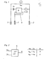
- Fig. l zeigt eine potentiostatisch arbeitende Anordnung mit Arbeitselektrode 1 (Kathode), Gegenelektrode 2 (Anode) und
Referenzelektrode 3 die durch denPotentiostat 4 verbunden sind. - Fig. 2 zeigt einen Grenzwertschalter mit Sollwertvergleich zur Verarbeitung des Differenzspannungssignals.
- 1 shows a potentiostatically working arrangement with working electrode 1 (cathode), counter electrode 2 (anode) and
reference electrode 3 which are connected by thepotentiostat 4. - 2 shows a limit switch with setpoint comparison for processing the differential voltage signal.
Für die übliche Meßpraxis, zumal im Labor und bei einfach zu regenerierenden Sensoren, ist es ausreichend, allein das Ende der Laufzeit einer Elektrolytfüllung zu signalisieren. Dazu ist es ausreichend, die Referenzelektrode ebenfalls als Elektrode 2. Art innerhalb der Elektrodenkammer auszuführen. Sinkt die Konzentration des Chlorids unter einen bestimmten Wert, so verändert sich die Potentialdifferenz URG zwischen der stromlosen Referenzelektrode und der stromdurchflossenen Gegenelektrode signifikant, so daß eine eindeutige Erkennung des Erschöpfungszustandes des Elektrolyten möglich ist. Die Veränderung der Potentialdifferenz kann leicht Werte von 100 mV und mehr annehmen.For normal measurement practice, especially in the laboratory and with easily regenerated sensors, it is sufficient to signal the end of the running time of an electrolyte fill alone. To do this, it is sufficient to also design the reference electrode as an electrode of the second type within the electrode chamber. If the concentration of the chloride drops below a certain value, the potential difference U RG between the currentless reference electrode and the current-carrying counter electrode changes significantly, so that a clear identification of the state of exhaustion of the electrolyte is possible. The change in the potential difference can easily assume values of 100 mV and more.
Die Auswertung solcher Potentialveränderungen ist auf verschiedene Weise möglich mit dem Fachmann bekannten Techniken. In einem analog arbeitenden Meßgerät werden nach Fig. 2 mittels Grenzwertschalter 5 die Potentialdifferenz URG und eine -Sollwertspannung Uw verglichen. Übersteigt URG den Wert von UW, so schaltet die Anordnung und am Ausgang Q steht ein entsprechendes Signal zur Weiterverarbeitung bereit. Bei digital arbeitenden Geräten sind softwaremäßige Lösungen ausführbar, indem die Potentiale von Referenz- und Gegenelektrode zyklisch über einen Multiplexer auf einen Analog/Digitalwandler gegeben und der Vergleich z. B. mit einem im Programm gespeicherten Sollwert erfolgt. Als Ausgangssignal steht dann an einer entsprechenden Schnittstelle ein Signal zur Verfügung, das dem der analogen Ausführung gleicht. Je nach Aufgabe des Geräts können auch mehrere Grenzwerte gesetzt werden, die z. B. nach Erreichen der ersten Grenze ein Alarmsignal - beispielsweise eine Blinkschaltung - betätigen und nach Überschreiten einer zweiten Schwelle den Meßkreis des Sensors unterbrechen. Bei benutzergeführten Geräten sind entsprechende Hinweise in der Anzeige möglich. Die schließliche Unterbrechung des Meßkreises schützt den Anwender vor Fehlmessungen.Such potential changes can be evaluated in various ways using techniques known to those skilled in the art. In an analog measuring device according to FIG. 2, the potential difference U RG and a —setpoint voltage U w are compared by means of
Claims (7)
Priority Applications (1)
| Application Number | Priority Date | Filing Date | Title |
|---|---|---|---|
| AT85105949T ATE68883T1 (en) | 1984-05-15 | 1985-05-14 | METHOD OF CHECKING THE RUNTIME STATE OF A MEMBRANE-COVERED POLAROGRAPHIC SENSOR. |
Applications Claiming Priority (2)
| Application Number | Priority Date | Filing Date | Title |
|---|---|---|---|
| DE3418034 | 1984-05-15 | ||
| DE19843418034 DE3418034A1 (en) | 1984-05-15 | 1984-05-15 | METHOD FOR CONTROLLING THE RUN TIME OF A MEMBRANE COVERED POLAROGRAPHIC SENSOR |
Publications (3)
| Publication Number | Publication Date |
|---|---|
| EP0161673A2 true EP0161673A2 (en) | 1985-11-21 |
| EP0161673A3 EP0161673A3 (en) | 1988-08-03 |
| EP0161673B1 EP0161673B1 (en) | 1991-10-23 |
Family
ID=6235904
Family Applications (1)
| Application Number | Title | Priority Date | Filing Date |
|---|---|---|---|
| EP85105949A Expired - Lifetime EP0161673B1 (en) | 1984-05-15 | 1985-05-14 | Method for controlling the operating condition of a polarographic membrane covered probe |
Country Status (4)
| Country | Link |
|---|---|
| EP (1) | EP0161673B1 (en) |
| AT (1) | ATE68883T1 (en) |
| DE (2) | DE3418034A1 (en) |
| DK (1) | DK164145C (en) |
Cited By (4)
| Publication number | Priority date | Publication date | Assignee | Title |
|---|---|---|---|---|
| EP0417347A1 (en) * | 1989-09-15 | 1991-03-20 | Hewlett-Packard GmbH | Electrochemical detector |
| EP1197751A2 (en) * | 2000-10-14 | 2002-04-17 | Endress + Hauser Conducta Gesellschaft für Mess- und Regeltechnik mbH + Co. | Amperometric measuring and detection method and apparatus for using the same |
| WO2002054056A1 (en) * | 2001-01-05 | 2002-07-11 | Mettler-Toledo Gmbh | Method for determining the remaining operation period of a potentiometric measuring probe, device for carrying out said method and the use thereof |
| EP2030561A1 (en) * | 2007-09-01 | 2009-03-04 | Roche Diagnostics GmbH | Sensor system for monitoring an analyte concentration in vivo and method for identifying a malfunction of such a sensor system |
Families Citing this family (7)
| Publication number | Priority date | Publication date | Assignee | Title |
|---|---|---|---|---|
| DE3809107A1 (en) * | 1988-03-18 | 1989-09-28 | Licentia Gmbh | Method for the automatic testing of the characteristic values of a sensor which is in operation and working on the basis of a change in resistance |
| DE3922147C2 (en) * | 1989-07-06 | 1998-11-12 | Me Meerestechnik Elektronik Gm | Gas partial pressure sensor with an electrolyte compartment sealed by a membrane |
| DE4131826A1 (en) * | 1991-09-20 | 1993-04-01 | Hl Planartechnik Gmbh | Amperometric sensor e.g. for oxygen sensor - has multi-surface working electrode in electrolyte with each portion of cathode surface smaller than its distance from inside of osmotic membrane |
| DE19510574C1 (en) * | 1995-03-23 | 1996-06-05 | Testo Gmbh & Co | Condition monitoring system for amperometric electrochemical gas sensor |
| DE19834808C2 (en) * | 1998-08-01 | 2003-07-03 | Conducta Endress & Hauser | Method for detecting a fault in a sensor for measuring the content of a gas dissolved in an aqueous medium |
| DE10209318B4 (en) * | 2002-03-02 | 2005-07-28 | Knick Elektronische Messgeräte GmbH & Co. KG | Method for determining the wear-dependent residual service life of an electrochemical measuring sensor |
| DE10253595A1 (en) * | 2002-11-15 | 2004-05-27 | Endress + Hauser Conducta Gesellschaft für Mess- und Regeltechnik mbH + Co. KG | Process for monitoring a reference half-cell comprises intermittently operating a measuring point in an operating mode and in a test mode, measuring the ion concentration in the operating mode, and testing the functionality |
Citations (3)
| Publication number | Priority date | Publication date | Assignee | Title |
|---|---|---|---|---|
| FR2138766A1 (en) * | 1971-05-21 | 1973-01-05 | Instrumentation Labor Inc | |
| GB1330295A (en) * | 1969-11-12 | 1973-09-12 | Plessey Co Ltd | Measurement of electrolytic conductivity |
| GB1447363A (en) * | 1972-11-01 | 1976-08-25 | Secretary Trade Ind Brit | Electrochemical cells |
Family Cites Families (1)
| Publication number | Priority date | Publication date | Assignee | Title |
|---|---|---|---|---|
| AT376045B (en) * | 1980-09-18 | 1984-10-10 | List Hans | METHOD FOR CHECKING THE CONDITION OF A POLAROGRAPHIC MEASURING ELECTRODE AND DEVICE FOR IMPLEMENTING THE METHOD |
-
1984
- 1984-05-15 DE DE19843418034 patent/DE3418034A1/en active Granted
-
1985
- 1985-05-09 DK DK204985A patent/DK164145C/en not_active IP Right Cessation
- 1985-05-14 DE DE8585105949T patent/DE3584466D1/en not_active Expired - Lifetime
- 1985-05-14 EP EP85105949A patent/EP0161673B1/en not_active Expired - Lifetime
- 1985-05-14 AT AT85105949T patent/ATE68883T1/en active
Patent Citations (3)
| Publication number | Priority date | Publication date | Assignee | Title |
|---|---|---|---|---|
| GB1330295A (en) * | 1969-11-12 | 1973-09-12 | Plessey Co Ltd | Measurement of electrolytic conductivity |
| FR2138766A1 (en) * | 1971-05-21 | 1973-01-05 | Instrumentation Labor Inc | |
| GB1447363A (en) * | 1972-11-01 | 1976-08-25 | Secretary Trade Ind Brit | Electrochemical cells |
Cited By (6)
| Publication number | Priority date | Publication date | Assignee | Title |
|---|---|---|---|---|
| EP0417347A1 (en) * | 1989-09-15 | 1991-03-20 | Hewlett-Packard GmbH | Electrochemical detector |
| EP1197751A2 (en) * | 2000-10-14 | 2002-04-17 | Endress + Hauser Conducta Gesellschaft für Mess- und Regeltechnik mbH + Co. | Amperometric measuring and detection method and apparatus for using the same |
| EP1197751A3 (en) * | 2000-10-14 | 2004-04-14 | Endress + Hauser Conducta Gesellschaft für Mess- und Regeltechnik mbH + Co.KG. | Amperometric measuring and detection method and apparatus for using the same |
| WO2002054056A1 (en) * | 2001-01-05 | 2002-07-11 | Mettler-Toledo Gmbh | Method for determining the remaining operation period of a potentiometric measuring probe, device for carrying out said method and the use thereof |
| EP2030561A1 (en) * | 2007-09-01 | 2009-03-04 | Roche Diagnostics GmbH | Sensor system for monitoring an analyte concentration in vivo and method for identifying a malfunction of such a sensor system |
| JP2009056311A (en) * | 2007-09-01 | 2009-03-19 | F Hoffmann-La Roche Ag | Measuring system for in vivo monitoring analyte concentration and method for detecting malfunction of such measuring system |
Also Published As
| Publication number | Publication date |
|---|---|
| EP0161673A3 (en) | 1988-08-03 |
| ATE68883T1 (en) | 1991-11-15 |
| DE3418034A1 (en) | 1985-11-21 |
| DE3418034C2 (en) | 1990-11-15 |
| EP0161673B1 (en) | 1991-10-23 |
| DE3584466D1 (en) | 1991-11-28 |
| DK204985D0 (en) | 1985-05-09 |
| DK164145B (en) | 1992-05-11 |
| DK204985A (en) | 1985-11-16 |
| DK164145C (en) | 1992-10-12 |
Similar Documents
| Publication | Publication Date | Title |
|---|---|---|
| WO2004025223A2 (en) | Method for monitoring sensor function | |
| EP0161673B1 (en) | Method for controlling the operating condition of a polarographic membrane covered probe | |
| DE102013109105A1 (en) | measuring arrangement | |
| WO2012019980A1 (en) | Measurement arrangement and method for ascertaining an analyte concentration in a measurement medium | |
| DE3844386C2 (en) | ||
| DE102012101254A1 (en) | Measuring arrangement and method for detecting an analyte concentration in a measuring medium | |
| Zirino et al. | Anodic stripping peak currents: electrolysis potential relations for reversible systems | |
| DE102014019337A1 (en) | CHLORINE DETERMINATION WITH PULSE AMPEROMETRIC DETECTION | |
| DE2627271A1 (en) | ELECTROCHEMICAL CELL WITH A POLAROGRAPHIC DEVICE WITH ION-SELECTIVE ELECTRODE AS WORKING ELECTRODE | |
| DE102015101191A1 (en) | Potentiometric sensor | |
| EP0247535A2 (en) | Reference electrode for ion activity measurement, especially for pH measurement | |
| EP0060533B1 (en) | Electrochemical analyser | |
| EP0780685B1 (en) | Amperometric sensor with two electrodes. | |
| EP1936366B1 (en) | Method and apparatus for monitoring an electrochemical half-cell | |
| WO1996005509A1 (en) | Method and device for the determination of substances in solution | |
| DE4029321C2 (en) | ||
| DE19834808C2 (en) | Method for detecting a fault in a sensor for measuring the content of a gas dissolved in an aqueous medium | |
| EP2293052B1 (en) | Water analysis measuring assembly | |
| EP0062250A2 (en) | Electroanalytical measuring method with error compensation and apparatus for using this method | |
| EP1561101A1 (en) | Method and device for monitoring a reference half cell | |
| Barbero et al. | The extraction of heterogeneous kinetic parameters from combined chronoamperometric and chronocoulometric data by a multiple regression procedure | |
| DD275924A1 (en) | AMPEROMETRIC MEASURING CELL FOR THE DETERMINATION OF SULFUR HYDROGEN IN GASES AND LIQUIDS | |
| DE10001923C1 (en) | Procedure for the determination of redox-active substances | |
| DE2605568A1 (en) | ELECTROCHEMICAL MEASURING ELECTRODE | |
| DD271179A1 (en) | DEVICE FOR THE ELECTROCHEMICAL DETERMINATION OF AMMONIA IN GASES |
Legal Events
| Date | Code | Title | Description |
|---|---|---|---|
| PUAI | Public reference made under article 153(3) epc to a published international application that has entered the european phase |
Free format text: ORIGINAL CODE: 0009012 |
|
| AK | Designated contracting states |
Designated state(s): AT BE CH DE FR GB IT LI NL |
|
| ITCL | It: translation for ep claims filed |
Representative=s name: FIAMMENGHI FIAMMENGHI RACHELI |
|
| TCNL | Nl: translation of patent claims filed | ||
| EL | Fr: translation of claims filed | ||
| PUAL | Search report despatched |
Free format text: ORIGINAL CODE: 0009013 |
|
| AK | Designated contracting states |
Kind code of ref document: A3 Designated state(s): AT BE CH DE FR GB IT LI NL |
|
| 17P | Request for examination filed |
Effective date: 19890130 |
|
| 17Q | First examination report despatched |
Effective date: 19900712 |
|
| GRAA | (expected) grant |
Free format text: ORIGINAL CODE: 0009210 |
|
| ITF | It: translation for a ep patent filed |
Owner name: FIAMMENGHI - DOMENIGHETTI |
|
| AK | Designated contracting states |
Kind code of ref document: B1 Designated state(s): AT BE CH DE FR GB IT LI NL |
|
| REF | Corresponds to: |
Ref document number: 68883 Country of ref document: AT Date of ref document: 19911115 Kind code of ref document: T |
|
| GBT | Gb: translation of ep patent filed (gb section 77(6)(a)/1977) | ||
| ET | Fr: translation filed | ||
| REF | Corresponds to: |
Ref document number: 3584466 Country of ref document: DE Date of ref document: 19911128 |
|
| PLBE | No opposition filed within time limit |
Free format text: ORIGINAL CODE: 0009261 |
|
| STAA | Information on the status of an ep patent application or granted ep patent |
Free format text: STATUS: NO OPPOSITION FILED WITHIN TIME LIMIT |
|
| 26N | No opposition filed | ||
| PGFP | Annual fee paid to national office [announced via postgrant information from national office to epo] |
Ref country code: BE Payment date: 19940511 Year of fee payment: 10 |
|
| PGFP | Annual fee paid to national office [announced via postgrant information from national office to epo] |
Ref country code: CH Payment date: 19940524 Year of fee payment: 10 Ref country code: AT Payment date: 19940524 Year of fee payment: 10 |
|
| PGFP | Annual fee paid to national office [announced via postgrant information from national office to epo] |
Ref country code: NL Payment date: 19940531 Year of fee payment: 10 |
|
| PG25 | Lapsed in a contracting state [announced via postgrant information from national office to epo] |
Ref country code: AT Effective date: 19950514 |
|
| PG25 | Lapsed in a contracting state [announced via postgrant information from national office to epo] |
Ref country code: LI Effective date: 19950531 Ref country code: CH Effective date: 19950531 Ref country code: BE Effective date: 19950531 |
|
| BERE | Be: lapsed |
Owner name: WTW G.M.B.H. Effective date: 19950531 |
|
| PG25 | Lapsed in a contracting state [announced via postgrant information from national office to epo] |
Ref country code: NL Effective date: 19951201 |
|
| REG | Reference to a national code |
Ref country code: CH Ref legal event code: PL |
|
| NLV4 | Nl: lapsed or anulled due to non-payment of the annual fee |
Effective date: 19951201 |
|
| REG | Reference to a national code |
Ref country code: GB Ref legal event code: IF02 |
|
| PGFP | Annual fee paid to national office [announced via postgrant information from national office to epo] |
Ref country code: GB Payment date: 20030523 Year of fee payment: 19 |
|
| PGFP | Annual fee paid to national office [announced via postgrant information from national office to epo] |
Ref country code: FR Payment date: 20030527 Year of fee payment: 19 |
|
| PGFP | Annual fee paid to national office [announced via postgrant information from national office to epo] |
Ref country code: DE Payment date: 20030530 Year of fee payment: 19 |
|
| PG25 | Lapsed in a contracting state [announced via postgrant information from national office to epo] |
Ref country code: GB Free format text: LAPSE BECAUSE OF NON-PAYMENT OF DUE FEES Effective date: 20040514 |
|
| PG25 | Lapsed in a contracting state [announced via postgrant information from national office to epo] |
Ref country code: DE Free format text: LAPSE BECAUSE OF NON-PAYMENT OF DUE FEES Effective date: 20041201 |
|
| GBPC | Gb: european patent ceased through non-payment of renewal fee |
Effective date: 20040514 |
|
| PG25 | Lapsed in a contracting state [announced via postgrant information from national office to epo] |
Ref country code: FR Free format text: LAPSE BECAUSE OF NON-PAYMENT OF DUE FEES Effective date: 20050131 |
|
| REG | Reference to a national code |
Ref country code: FR Ref legal event code: ST |