EP0161260B1 - Method for the abrasive treatment of a casting - Google Patents
Method for the abrasive treatment of a casting Download PDFInfo
- Publication number
- EP0161260B1 EP0161260B1 EP19840902312 EP84902312A EP0161260B1 EP 0161260 B1 EP0161260 B1 EP 0161260B1 EP 19840902312 EP19840902312 EP 19840902312 EP 84902312 A EP84902312 A EP 84902312A EP 0161260 B1 EP0161260 B1 EP 0161260B1
- Authority
- EP
- European Patent Office
- Prior art keywords
- casting
- media
- vibrated
- vibrating
- acceleration
- Prior art date
- Legal status (The legal status is an assumption and is not a legal conclusion. Google has not performed a legal analysis and makes no representation as to the accuracy of the status listed.)
- Expired
Links
Images

Classifications
-
- B—PERFORMING OPERATIONS; TRANSPORTING
- B24—GRINDING; POLISHING
- B24B—MACHINES, DEVICES, OR PROCESSES FOR GRINDING OR POLISHING; DRESSING OR CONDITIONING OF ABRADING SURFACES; FEEDING OF GRINDING, POLISHING, OR LAPPING AGENTS
- B24B31/00—Machines or devices designed for polishing or abrading surfaces on work by means of tumbling apparatus or other apparatus in which the work and/or the abrasive material is loose; Accessories therefor
- B24B31/06—Machines or devices designed for polishing or abrading surfaces on work by means of tumbling apparatus or other apparatus in which the work and/or the abrasive material is loose; Accessories therefor involving oscillating or vibrating containers
- B24B31/064—Machines or devices designed for polishing or abrading surfaces on work by means of tumbling apparatus or other apparatus in which the work and/or the abrasive material is loose; Accessories therefor involving oscillating or vibrating containers the workpieces being fitted on a support
-
- B—PERFORMING OPERATIONS; TRANSPORTING
- B22—CASTING; POWDER METALLURGY
- B22D—CASTING OF METALS; CASTING OF OTHER SUBSTANCES BY THE SAME PROCESSES OR DEVICES
- B22D29/00—Removing castings from moulds, not restricted to casting processes covered by a single main group; Removing cores; Handling ingots
- B22D29/001—Removing cores
- B22D29/005—Removing cores by vibrating or hammering
-
- B—PERFORMING OPERATIONS; TRANSPORTING
- B22—CASTING; POWDER METALLURGY
- B22D—CASTING OF METALS; CASTING OF OTHER SUBSTANCES BY THE SAME PROCESSES OR DEVICES
- B22D31/00—Cutting-off surplus material, e.g. gates; Cleaning and working on castings
- B22D31/002—Cleaning, working on castings
Definitions
- This invention relates to a method and apparatus for the abrasive treatment of a workpiece according to the preambles of claims 1 and 4.
- a specific example of the general problem is in the casting industry wherein a variety of metal casting processes are used, with one such process involving the use of inexpensive styrofoam patterns which have been coated with a ceramic-type material.
- the patterns can be formed with intricate shapes having depressions, cavities, internal passages, crevices, chambers and the like.
- the pattern is positioned in a mould box and sand is formed therearound ready for casting.
- the styrofoam pattern melts away while the ceramic-type coating holds its shape long enough to form the metal casting.
- the ceramic type coating however also breaks up during the process and in doing so leaves particles of coating of foreign material or of sand adhered to the internal and external surfaces of the casting.
- a method for the abrasive treatment of a part comprising vibrating a mass of abrasive media substantially in a vertical direction, moving the workpiece to be abrasively treated within the vibrated media, and raising the workpiece when it has been abrasively treated substantially in a vertical direction out of the media.
- the part to be abrasively treated is a rotationally symmetrical workpiece which is moved within the vibrated media by being rotated about a fixed axis.
- the method of GB-A-1067656 is not suitable for abrasively treating castings most of which are not symmetrical, since to rotate them in vibrated media will clean and wearthe corners but leave the low areas on the casting untouched.
- the aforesaid generally disclosed method is characterised in that the workpiece to be abrasively treated is a casting with internal and external surfaces, the casting is moved within the vibrated media by being vibrated substantially in a vertical direction with a frequency and amplitude to produce an acceleration of the casting greater than 1 g, the media is vibrated with a frequency and amplitude to produce an acceleration thereof also greater than 1g by which the media will fluidize and flow across the internal and external surfaces of the vibrating casting to scrub particles therefrom, and the abrasively treated casting is raised, whilst still being vibrated, out of the media by which the media and freed particles are removed from the casting.
- An advantage of the method of the invention over the method disclosed in GB-A-1067656 is that it is suitable for abrasively treating not only assymmetrical castings but also castings in general having internal and external surfaces formed by depressions, cavities, internal passages, crevices, chambers and the like, since the media in the fluidized state will flow into all such areas to clean the casting inside and out. Moreover, by vibrating the casting itself and continuing to vibrate it as it is raised and removed from the media ensures that the free particles scrubbed from the casting as well as any media adhering thereto will be discharged, leaving the casting clean.
- An apparatus for carrying out the method generally disclosed in GB-A-1067696 generally comprises a container of abrasive media, means for vibrating the container to vibrate the media therein substantially in a vertical direction, means for moving the workpiece to be abrasively treated within the vibrated media, and means for raising the workpiece when it has been abrasively treated substantially in a vertical direction out of the media.
- the aforesaid generally disclosed apparatus of GB-A-1067696 is characterised in that the apparatus is for the abrasive treatment of a workpiece in the form of a casting with internal surfaces and external surfaces, the means for moving the casting within the vibrated media is operable to vibrate the casting substantially in a vertical direction, the means for vibrating the container is operable to vibrate the media with a frequency and amplitude to produce an acceleration thereof greater than 1 g by which the media will fludize and flow across the internal and external surfaces of the vibrated casting to scrub particles therefrom, and the means for raising the casting out of the media is operable to do so, whilst the casting vibrating means is vibrating the casting, by which to assist removal of the media and freed particles from the casting.
- a vibratory scrubber 10 is shown specifically as scrubbing a casting.
- the scrubber 10 includes a container 12 for particulate scrubbing media 14, such as steel shot, mixture of liquid and solids or any other fluidizable material, and the container 12 is fixed to a platform 16. Due to the weight of the container 12 and media 14, it is necessary to have a suitably reinforced platform 16, as for example by connecting spaced plates 18, 20 with a bracing structure 22.
- the platform 16 is mounted on four corners to springs 24 which are themselves mounted on a base 26 suitably secured to the floor 30.
- a set of vibration generators 34 of any well known type is provided with the vibration generators shown being in the form of electric motors 36 having shafts 38 carrying eccentric weights 40.
- the generators are suspended from the bottom of the platform 16 in order to produce the vibrations.
- the vibration generators 34 may be of the type shown in U.S. Patent No. 3,358,815 where the effective force of the eccentric weights may be varied from zero to maximum and thus produce a variation in stroke as desired.
- Other types of vibration generators could be substituted for the eccentric vibration generators 34, such as hydraulic vibrators and the like.
- the vibration generators 34 are energized to produce a vibratory motion for the container 12 and its contents substantially in a vertical direction and in excess of the acceleration due to gravity i.e. greater than 1g.
- the acceleration in g's can be calculated by the formula where S is the amplitude of the stroke in inches and F is the frequency of the stroke in strokes per minute. For example, with a frequency of 3600 strokes per minute and a stroke amplitude of 0.007 inches, there is produced an acceleration of 1.29 g's on the container 12 and the media 14. This acceleration causes the media 14 to become fluidized, and thereby to flow freely.
- a part or casting supporting structure 44 Suspended by a chain 42 above the container 12 is a part or casting supporting structure 44 comprised of a frame 46, made of I-beams 48, having sufficient rigidity to support and vibrate in a substantially vertical direction a part or casting 50.
- a mounting beam 52 depends vertically downward from the frame 46 and is adaptable for mounting a desired number and type of part or casting 50.
- two castings 50, 50 are fixed to the mounting beam 52 by bolting flanges 54 of the castings 50 onto the mounting beam 52.
- other means of fixing the parts or castings 50 shown, as well as other types of parts or castings, to the mounting beam 52 would be suitable and apparent to those skilled in the art. It is important that the openings 53 into the passageways 55 be kept open and unobstructed so that the media 14 can flow freely into and out of the passageways.
- the frame 46 is directly connected to a second set of vibration generators 60, each of which in the illustrated form also comprises an electric motor 62 driving a shaft 64 having synchronized eccentric weights 66 on both ends.
- a second set of vibration generators 60 each of which in the illustrated form also comprises an electric motor 62 driving a shaft 64 having synchronized eccentric weights 66 on both ends.
- the second set of vibration generators 60 are suspended from an upper plate 70 by a pair of springs 72.
- the upper plate 70 has a bracket 74 which is connected to the supporting chain 42.
- the upper plate 70 is isolated from the vibrations of the vibration generators 60 by the springs 72.
- Suitable means are provided to manipulate the chain 42 so as to lower the frame 46 and mounting beam 52 to locate the castings 50 in the media 14, and also to raise the frame 46 from the media ready for removal of the castings or parts 50.
- Castings or parts 50 may be manufactured using styrofoam patterns which have been coated with a ceramic-type material. During the casting process, the styrofoam pattern is essentially melted away and the ceramic-type coating holds its shape long enough to form the casting 50 but then breaks up as well. This process leaves particles or foreign material 80 (see Figure 3) of the coating as well as other materials adhered to the external surfaces 82 and internal surface 84 of the casting 50. The scrubber 10 is used to remove these particles or foreign material 80 from all surfaces both external 82 and internal 84 of the casting 50.
- the castings or parts 50 are fixed to the mounting beam 52 and then the vibration generator 34 for the container 12 and media and the generator 60 for the frame 46 and parts 50 are energized.
- the vibrating frame 46 is lowered to locate the parts or castings 50 into the vibrating media 14 which is easily accomplished inasmuch as the media 14 in the container 12 is fluidized by the vibrations of the generators 34.
- the media 14 thus easily flows about the casting 50 and into crevices and passageways in the casting 50, and the vibration of the casting 50 itself ensures that the media 14 will flow freely into any such crevices and passageways in the casting 50 as well.
- the vibration generators 60 on the supporting structure 44 may continue to be driven as the structure 44 is raised to remove the part or casting 50 from the container 12 so as to discharge the media and freed foreign material or particles 80 from the passageways 55 in the parts or castings.
- FIG. 5 An alternative embodiment of the vibratory scrubber 10' is shown in Figure 5.
- the same reference numerals are used for the members that are identical to Figure 1.
- This scrubber 10' uses a two mass sytem for vibrating the part or casting 50.
- the set of vibration generators 60 used to apply a vibratory motion to the frame 52 and part 50 are not directly attached to the frame 46', but rather are attached to a second set of springs 88 extending between the first set of vibration generators 60 and a working weight 90 carried by the frame 46' and mounting beam 52.
- the second set of springs 88 are used to tune the vibrations of the frame 46 for enhacing the vibratory motion of the part or casting 50.
- the casting may be vibrated at a frequency and amplitude to produce an acceleration thereof that varies from the acceleration produced on the media by the frequency and amplitude at which the media is vibrated, both such accelerations being greater than 1g.
Abstract
Description
- This invention relates to a method and apparatus for the abrasive treatment of a workpiece according to the preambles of claims 1 and 4.
- In many manufacturing and assembly processes foreign material may be adhered to or deposited on the internal and external surfaces of the part being manufactured. The foreign material must be removed before the part is put into an assembly or into use.
- A specific example of the general problem is in the casting industry wherein a variety of metal casting processes are used, with one such process involving the use of inexpensive styrofoam patterns which have been coated with a ceramic-type material. The patterns can be formed with intricate shapes having depressions, cavities, internal passages, crevices, chambers and the like. The pattern is positioned in a mould box and sand is formed therearound ready for casting. During the casting process, the styrofoam pattern melts away while the ceramic-type coating holds its shape long enough to form the metal casting. The ceramic type coating however also breaks up during the process and in doing so leaves particles of coating of foreign material or of sand adhered to the internal and external surfaces of the casting. Such particles or foreign material are, of course, undesirable in the finished product, and thus it is desirable to remove those particles. However, inasmuch as many castings will have internal passages, holes, crevices, chambers and the like which are hard to reach, the removal of those particles is difficult.
- All mouldings systems suffer, in varying degrees, the same shortcomings, namely, leaving residual particles of foreign material of the pattern and the moulding sand on the external surfaces and in the internal surfaces of the castings. The residual particles need to be purged from the casting before the casting is processed further and/or put into use.
- In GB-A-1067656, upon which the preamble of claims 1 and 4 are based, there is generally disclosed a method for the abrasive treatment of a part, comprising vibrating a mass of abrasive media substantially in a vertical direction, moving the workpiece to be abrasively treated within the vibrated media, and raising the workpiece when it has been abrasively treated substantially in a vertical direction out of the media.
- More particularly, the part to be abrasively treated is a rotationally symmetrical workpiece which is moved within the vibrated media by being rotated about a fixed axis. As such, the method of GB-A-1067656 is not suitable for abrasively treating castings most of which are not symmetrical, since to rotate them in vibrated media will clean and wearthe corners but leave the low areas on the casting untouched.
- In accordance with the present invention as claimed, the aforesaid generally disclosed method is characterised in that the workpiece to be abrasively treated is a casting with internal and external surfaces, the casting is moved within the vibrated media by being vibrated substantially in a vertical direction with a frequency and amplitude to produce an acceleration of the casting greater than 1 g, the media is vibrated with a frequency and amplitude to produce an acceleration thereof also greater than 1g by which the media will fluidize and flow across the internal and external surfaces of the vibrating casting to scrub particles therefrom, and the abrasively treated casting is raised, whilst still being vibrated, out of the media by which the media and freed particles are removed from the casting.
- An advantage of the method of the invention over the method disclosed in GB-A-1067656 is that it is suitable for abrasively treating not only assymmetrical castings but also castings in general having internal and external surfaces formed by depressions, cavities, internal passages, crevices, chambers and the like, since the media in the fluidized state will flow into all such areas to clean the casting inside and out. Moreover, by vibrating the casting itself and continuing to vibrate it as it is raised and removed from the media ensures that the free particles scrubbed from the casting as well as any media adhering thereto will be discharged, leaving the casting clean.
- An apparatus for carrying out the method generally disclosed in GB-A-1067696 generally comprises a container of abrasive media, means for vibrating the container to vibrate the media therein substantially in a vertical direction, means for moving the workpiece to be abrasively treated within the vibrated media, and means for raising the workpiece when it has been abrasively treated substantially in a vertical direction out of the media.
- As said hereinbefore, in GB-A-1067696 the workpiece is moved within the vibrated media by being rotated about a fixed axis which, whilst suitable for rotationally symmetrical workpieces, is not for the majority of castings.
- The aforesaid generally disclosed apparatus of GB-A-1067696, in accordance with the present invention, is characterised in that the apparatus is for the abrasive treatment of a workpiece in the form of a casting with internal surfaces and external surfaces, the means for moving the casting within the vibrated media is operable to vibrate the casting substantially in a vertical direction, the means for vibrating the container is operable to vibrate the media with a frequency and amplitude to produce an acceleration thereof greater than 1 g by which the media will fludize and flow across the internal and external surfaces of the vibrated casting to scrub particles therefrom, and the means for raising the casting out of the media is operable to do so, whilst the casting vibrating means is vibrating the casting, by which to assist removal of the media and freed particles from the casting.
- Thereby, use of the apparatus of the invention results in the hereinbefore stated advantages over GB-A-1067656.
- In order that the invention may be well understood there will now be described some embodiments thereof, given by way of example, reference being made to the accompanying drawings, in which:
- Figure 1 is a partial cross-sectional view of a first embodiment of a vibratory scrubber;
- Figure 2 is a view taken along line 2-2 of Figure 1;
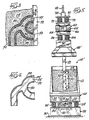
- Figure 3 is a partial enlarged cross-sectional view taken along line 3-3 of Figure 1;
- Figure 4 is a cross-sectional view of a portion of the casting of Figure 3 after scrubbing by the scrubber; and
- Figure 5 is a partial cross-sectional view similar to Figure 1 of an alternative embodiment of a vibratory scrubber.
- Referring first to Figures 1 and 2, a
vibratory scrubber 10 is shown specifically as scrubbing a casting. Thescrubber 10 includes acontainer 12 forparticulate scrubbing media 14, such as steel shot, mixture of liquid and solids or any other fluidizable material, and thecontainer 12 is fixed to aplatform 16. Due to the weight of thecontainer 12 andmedia 14, it is necessary to have a suitably reinforcedplatform 16, as for example by connectingspaced plates bracing structure 22. - The
platform 16 is mounted on four corners tosprings 24 which are themselves mounted on abase 26 suitably secured to thefloor 30. - A set of
vibration generators 34 of any well known type is provided with the vibration generators shown being in the form ofelectric motors 36 havingshafts 38 carrying eccentric weights 40. The generators are suspended from the bottom of theplatform 16 in order to produce the vibrations. Thevibration generators 34 may be of the type shown in U.S. Patent No. 3,358,815 where the effective force of the eccentric weights may be varied from zero to maximum and thus produce a variation in stroke as desired. Other types of vibration generators could be substituted for theeccentric vibration generators 34, such as hydraulic vibrators and the like. - The
vibration generators 34 are energized to produce a vibratory motion for thecontainer 12 and its contents substantially in a vertical direction and in excess of the acceleration due to gravity i.e. greater than 1g. The acceleration in g's can be calculated by the formula
container 12 and themedia 14. This acceleration causes themedia 14 to become fluidized, and thereby to flow freely. - Suspended by a
chain 42 above thecontainer 12 is a part or casting supportingstructure 44 comprised of aframe 46, made of I-beams 48, having sufficient rigidity to support and vibrate in a substantially vertical direction a part or casting 50. Amounting beam 52 depends vertically downward from theframe 46 and is adaptable for mounting a desired number and type of part or casting 50. In the embodiment shown, twocastings mounting beam 52 by boltingflanges 54 of thecastings 50 onto themounting beam 52. Of course, other means of fixing the parts orcastings 50 shown, as well as other types of parts or castings, to themounting beam 52 would be suitable and apparent to those skilled in the art. It is important that theopenings 53 into thepassageways 55 be kept open and unobstructed so that themedia 14 can flow freely into and out of the passageways. - The
frame 46 is directly connected to a second set ofvibration generators 60, each of which in the illustrated form also comprises anelectric motor 62 driving ashaft 64 having synchronizedeccentric weights 66 on both ends. As with thevibration generators 34 of thecontainer 12, it is desirable to drive the second set of vibration generators so that the frame and hence the part orcastings 50 is vibrated substantially in a vertical direction and in a manner in which the
- The second set of
vibration generators 60 are suspended from anupper plate 70 by a pair ofsprings 72. Theupper plate 70 has abracket 74 which is connected to the supportingchain 42. Theupper plate 70 is isolated from the vibrations of thevibration generators 60 by thesprings 72. Suitable means are provided to manipulate thechain 42 so as to lower theframe 46 and mountingbeam 52 to locate thecastings 50 in themedia 14, and also to raise theframe 46 from the media ready for removal of the castings orparts 50. - Castings or
parts 50 may be manufactured using styrofoam patterns which have been coated with a ceramic-type material. During the casting process, the styrofoam pattern is essentially melted away and the ceramic-type coating holds its shape long enough to form thecasting 50 but then breaks up as well. This process leaves particles or foreign material 80 (see Figure 3) of the coating as well as other materials adhered to theexternal surfaces 82 andinternal surface 84 of thecasting 50. Thescrubber 10 is used to remove these particles orforeign material 80 from all surfaces both external 82 and internal 84 of thecasting 50. - To remove the particles or
foreign material 80, the castings orparts 50 are fixed to themounting beam 52 and then thevibration generator 34 for thecontainer 12 and media and thegenerator 60 for theframe 46 andparts 50 are energized. The vibratingframe 46 is lowered to locate the parts or castings 50 into the vibratingmedia 14 which is easily accomplished inasmuch as themedia 14 in thecontainer 12 is fluidized by the vibrations of thegenerators 34. Themedia 14 thus easily flows about thecasting 50 and into crevices and passageways in thecasting 50, and the vibration of thecasting 50 itself ensures that themedia 14 will flow freely into any such crevices and passageways in thecasting 50 as well. The flow of themedia 14 about theexternal surfaces 82 and through the passageways over theinternal surfaces 84 in thecastings 50 is abrasive on the surfaces of thecastings 50 and thus the particles orforeign materials 80 are scrubbed clean from the parts or castings. The result in a clean and, with certain types of materials,shiny casting 50 as shown in Figure 4. - The
vibration generators 60 on the supportingstructure 44 may continue to be driven as thestructure 44 is raised to remove the part or casting 50 from thecontainer 12 so as to discharge the media and freed foreign material orparticles 80 from thepassageways 55 in the parts or castings. - An alternative embodiment of the vibratory scrubber 10' is shown in Figure 5. The same reference numerals are used for the members that are identical to Figure 1. This scrubber 10' uses a two mass sytem for vibrating the part or casting 50. With the scrubber of Figure 5, the set of
vibration generators 60 used to apply a vibratory motion to theframe 52 andpart 50 are not directly attached to the frame 46', but rather are attached to a second set ofsprings 88 extending between the first set ofvibration generators 60 and a workingweight 90 carried by the frame 46' and mountingbeam 52. The second set ofsprings 88 are used to tune the vibrations of theframe 46 for enhacing the vibratory motion of the part or casting 50. - As another alternative, the casting may be vibrated at a frequency and amplitude to produce an acceleration thereof that varies from the acceleration produced on the media by the frequency and amplitude at which the media is vibrated, both such accelerations being greater than 1g.
Claims (10)
Applications Claiming Priority (2)
| Application Number | Priority Date | Filing Date | Title |
|---|---|---|---|
| US54982783A | 1983-11-09 | 1983-11-09 | |
| US549827 | 1983-11-09 |
Publications (3)
| Publication Number | Publication Date |
|---|---|
| EP0161260A1 EP0161260A1 (en) | 1985-11-21 |
| EP0161260A4 EP0161260A4 (en) | 1986-02-20 |
| EP0161260B1 true EP0161260B1 (en) | 1989-08-23 |
Family
ID=24194515
Family Applications (1)
| Application Number | Title | Priority Date | Filing Date |
|---|---|---|---|
| EP19840902312 Expired EP0161260B1 (en) | 1983-11-09 | 1984-05-29 | Method for the abrasive treatment of a casting |
Country Status (6)
| Country | Link |
|---|---|
| EP (1) | EP0161260B1 (en) |
| JP (1) | JPS61500351A (en) |
| AU (1) | AU558075B2 (en) |
| DE (1) | DE3479484D1 (en) |
| FI (1) | FI77170C (en) |
| WO (1) | WO1985002136A1 (en) |
Cited By (1)
| Publication number | Priority date | Publication date | Assignee | Title |
|---|---|---|---|---|
| EP3225356B1 (en) * | 2016-04-01 | 2023-03-01 | Rolls-Royce plc | Methods of vibro-treating and vibro-treating apparatus |
Families Citing this family (7)
| Publication number | Priority date | Publication date | Assignee | Title |
|---|---|---|---|---|
| FR2649919B1 (en) * | 1989-07-21 | 1991-10-04 | Peugeot | INSTALLATION FOR CLEANING FOUNDRY PARTS |
| JP2550231B2 (en) * | 1991-06-18 | 1996-11-06 | 株式会社日立製作所 | Method of manufacturing magnetic recording medium |
| DE59901771D1 (en) * | 1998-11-14 | 2002-07-18 | Mtu Aero Engines Gmbh | ARRANGEMENT FOR FINISHING ROTATION-SYMMETRICAL COMPONENTS |
| JP2010131675A (en) * | 2007-03-02 | 2010-06-17 | Ee P C Aero Specialty Kk | Vibratory polishing method and apparatus |
| US10678896B2 (en) | 2015-06-30 | 2020-06-09 | Samsung Electronics Co., Ltd. | Methods and apparatuses for updating user authentication data |
| US20220331930A1 (en) * | 2019-10-10 | 2022-10-20 | 3M Innovative Properties Company | Method of modifying a surface of a workpiece |
| JP7331637B2 (en) * | 2019-11-05 | 2023-08-23 | トヨタ自動車株式会社 | Deposit removal method |
Family Cites Families (8)
| Publication number | Priority date | Publication date | Assignee | Title |
|---|---|---|---|---|
| US3230669A (en) * | 1963-03-05 | 1966-01-25 | Boeing Co | Deburring apparatus |
| GB1067656A (en) * | 1965-12-22 | 1967-05-03 | Wissenchaftlich Tech Zentrum A | Method for the abrasive treatment of workpieces |
| US3581440A (en) * | 1969-05-27 | 1971-06-01 | Shell Oil Co | Resonant apparatus for cleaning castings and the like |
| JPS5038860U (en) * | 1973-08-08 | 1975-04-22 | ||
| JPS583960Y2 (en) * | 1978-09-27 | 1983-01-24 | 株式会社日立製作所 | piston |
| SU799940A1 (en) * | 1979-04-11 | 1981-01-30 | Среднеазиатский Филиал Государственноговсесоюзного Ордена Трудовогокрасного Знамени Научно-Исследо-Вательского И Технологическогоинститута Pemohta И Эксплуатациимашинно-Тракторного Парка | Unit for vibration-cleaning of articles |
| CA1177221A (en) * | 1980-12-04 | 1984-11-06 | General Kinematics Corporation | Vibratory method for packing foundry sand into a pattern prior to the pouring of molten metal |
| JPS5947156A (en) * | 1982-09-10 | 1984-03-16 | Shintou Bureetaa Kk | Method and device for polishing hydraulically vibrating surface |
-
1984
- 1984-05-29 JP JP50228384A patent/JPS61500351A/en active Granted
- 1984-05-29 DE DE8484902312T patent/DE3479484D1/en not_active Expired
- 1984-05-29 EP EP19840902312 patent/EP0161260B1/en not_active Expired
- 1984-05-29 WO PCT/US1984/000826 patent/WO1985002136A1/en active IP Right Grant
- 1984-05-29 AU AU29671/84A patent/AU558075B2/en not_active Ceased
-
1985
- 1985-07-08 FI FI852702A patent/FI77170C/en not_active IP Right Cessation
Cited By (1)
| Publication number | Priority date | Publication date | Assignee | Title |
|---|---|---|---|---|
| EP3225356B1 (en) * | 2016-04-01 | 2023-03-01 | Rolls-Royce plc | Methods of vibro-treating and vibro-treating apparatus |
Also Published As
| Publication number | Publication date |
|---|---|
| FI77170B (en) | 1988-10-31 |
| EP0161260A1 (en) | 1985-11-21 |
| AU2967184A (en) | 1985-06-03 |
| AU558075B2 (en) | 1987-01-15 |
| JPS61500351A (en) | 1986-03-06 |
| DE3479484D1 (en) | 1989-09-28 |
| WO1985002136A1 (en) | 1985-05-23 |
| FI77170C (en) | 1989-02-10 |
| JPH0547349B2 (en) | 1993-07-16 |
| FI852702A0 (en) | 1985-07-08 |
| EP0161260A4 (en) | 1986-02-20 |
| FI852702L (en) | 1985-07-08 |
Similar Documents
| Publication | Publication Date | Title |
|---|---|---|
| US3989537A (en) | Method and apparatus for vibration cleaning of workpieces such as engine blocks | |
| EP0161260B1 (en) | Method for the abrasive treatment of a casting | |
| US4991360A (en) | Method and apparatus for surface treating a workpiece | |
| US4662425A (en) | Vibratory part scrubber and method | |
| US4722386A (en) | Casting core shakeout | |
| US4716684A (en) | Cleaning and deburring of machined or cast parts | |
| US4299692A (en) | Apparatus for handling a mold box in a vacuum casting system | |
| US4671867A (en) | Method and means for treating foundry sands and the like | |
| US5271184A (en) | Vibratory finishing apparatus for hollow cylindrical and other large or groupings of articles | |
| US3584419A (en) | Apparatus and method for cleaning hollow castings | |
| US3685213A (en) | Orbital finishing system | |
| CA1267886A (en) | Tumbling apparatus | |
| US4731959A (en) | Vibratory casting cleaning | |
| US4829714A (en) | Devurring and cleaning machine and process | |
| JP4045727B2 (en) | Micropart sieving equipment | |
| US4780993A (en) | Method and apparatus for surface treating a workpiece | |
| US4001984A (en) | Method for finishing parts | |
| US3214871A (en) | Apparatus and method for treating coated electrodes and the like | |
| CA1049742A (en) | Vibratory sand reclaiming apparatus | |
| US4916865A (en) | Apparatus for surface treating a workpiece | |
| US3544292A (en) | Granular cleaner | |
| JPH0659518B2 (en) | Equipment for processing particulates and other | |
| JP2001239224A (en) | Vibration type deburring and cleaning device | |
| SU1263501A1 (en) | Apparatus for working by vibration | |
| CA2053184A1 (en) | Process and device for cleaning of bulk goods |
Legal Events
| Date | Code | Title | Description |
|---|---|---|---|
| PUAI | Public reference made under article 153(3) epc to a published international application that has entered the european phase |
Free format text: ORIGINAL CODE: 0009012 |
|
| 17P | Request for examination filed |
Effective date: 19850529 |
|
| AK | Designated contracting states |
Designated state(s): BE CH DE FR GB LI SE |
|
| A4 | Supplementary search report drawn up and despatched |
Effective date: 19860220 |
|
| 17Q | First examination report despatched |
Effective date: 19870216 |
|
| GRAA | (expected) grant |
Free format text: ORIGINAL CODE: 0009210 |
|
| AK | Designated contracting states |
Kind code of ref document: B1 Designated state(s): BE CH DE FR GB LI SE |
|
| REF | Corresponds to: |
Ref document number: 3479484 Country of ref document: DE Date of ref document: 19890928 |
|
| ET | Fr: translation filed | ||
| PLBE | No opposition filed within time limit |
Free format text: ORIGINAL CODE: 0009261 |
|
| STAA | Information on the status of an ep patent application or granted ep patent |
Free format text: STATUS: NO OPPOSITION FILED WITHIN TIME LIMIT |
|
| 26N | No opposition filed | ||
| PGFP | Annual fee paid to national office [announced via postgrant information from national office to epo] |
Ref country code: FR Payment date: 19940413 Year of fee payment: 11 |
|
| PGFP | Annual fee paid to national office [announced via postgrant information from national office to epo] |
Ref country code: CH Payment date: 19940414 Year of fee payment: 11 |
|
| PGFP | Annual fee paid to national office [announced via postgrant information from national office to epo] |
Ref country code: SE Payment date: 19940415 Year of fee payment: 11 |
|
| PGFP | Annual fee paid to national office [announced via postgrant information from national office to epo] |
Ref country code: BE Payment date: 19940426 Year of fee payment: 11 |
|
| EAL | Se: european patent in force in sweden |
Ref document number: 84902312.2 |
|
| PG25 | Lapsed in a contracting state [announced via postgrant information from national office to epo] |
Ref country code: SE Effective date: 19950530 |
|
| PG25 | Lapsed in a contracting state [announced via postgrant information from national office to epo] |
Ref country code: LI Effective date: 19950531 Ref country code: CH Effective date: 19950531 Ref country code: BE Effective date: 19950531 |
|
| BERE | Be: lapsed |
Owner name: GENERAL KINEMATICS CORP. Effective date: 19950531 |
|
| REG | Reference to a national code |
Ref country code: CH Ref legal event code: PL |
|
| EUG | Se: european patent has lapsed |
Ref document number: 84902312.2 |
|
| PG25 | Lapsed in a contracting state [announced via postgrant information from national office to epo] |
Ref country code: FR Effective date: 19960229 |
|
| REG | Reference to a national code |
Ref country code: FR Ref legal event code: ST |
|
| REG | Reference to a national code |
Ref country code: FR Ref legal event code: ST |
|
| REG | Reference to a national code |
Ref country code: GB Ref legal event code: IF02 |
|
| PGFP | Annual fee paid to national office [announced via postgrant information from national office to epo] |
Ref country code: DE Payment date: 20020520 Year of fee payment: 19 |
|
| PGFP | Annual fee paid to national office [announced via postgrant information from national office to epo] |
Ref country code: GB Payment date: 20020522 Year of fee payment: 19 |
|
| PG25 | Lapsed in a contracting state [announced via postgrant information from national office to epo] |
Ref country code: GB Free format text: LAPSE BECAUSE OF NON-PAYMENT OF DUE FEES Effective date: 20030529 |
|
| PG25 | Lapsed in a contracting state [announced via postgrant information from national office to epo] |
Ref country code: DE Free format text: LAPSE BECAUSE OF NON-PAYMENT OF DUE FEES Effective date: 20031202 |
|
| GBPC | Gb: european patent ceased through non-payment of renewal fee |
Effective date: 20030529 |