EP0161237B1 - Hydraulically-operated directional-control valve - Google Patents
Hydraulically-operated directional-control valve Download PDFInfo
- Publication number
- EP0161237B1 EP0161237B1 EP85890104A EP85890104A EP0161237B1 EP 0161237 B1 EP0161237 B1 EP 0161237B1 EP 85890104 A EP85890104 A EP 85890104A EP 85890104 A EP85890104 A EP 85890104A EP 0161237 B1 EP0161237 B1 EP 0161237B1
- Authority
- EP
- European Patent Office
- Prior art keywords
- switching
- bores
- index
- bore
- medium
- Prior art date
- Legal status (The legal status is an assumption and is not a legal conclusion. Google has not performed a legal analysis and makes no representation as to the accuracy of the status listed.)
- Expired
Links
- 230000002093 peripheral effect Effects 0.000 claims 3
- 210000003739 neck Anatomy 0.000 claims 1
- 125000006850 spacer group Chemical group 0.000 claims 1
- 238000005070 sampling Methods 0.000 abstract 1
Images


Classifications
-
- F—MECHANICAL ENGINEERING; LIGHTING; HEATING; WEAPONS; BLASTING
- F15—FLUID-PRESSURE ACTUATORS; HYDRAULICS OR PNEUMATICS IN GENERAL
- F15B—SYSTEMS ACTING BY MEANS OF FLUIDS IN GENERAL; FLUID-PRESSURE ACTUATORS, e.g. SERVOMOTORS; DETAILS OF FLUID-PRESSURE SYSTEMS, NOT OTHERWISE PROVIDED FOR
- F15B21/00—Common features of fluid actuator systems; Fluid-pressure actuator systems or details thereof, not covered by any other group of this subclass
- F15B21/12—Fluid oscillators or pulse generators
- F15B21/125—Fluid oscillators or pulse generators by means of a rotating valve
-
- Y—GENERAL TAGGING OF NEW TECHNOLOGICAL DEVELOPMENTS; GENERAL TAGGING OF CROSS-SECTIONAL TECHNOLOGIES SPANNING OVER SEVERAL SECTIONS OF THE IPC; TECHNICAL SUBJECTS COVERED BY FORMER USPC CROSS-REFERENCE ART COLLECTIONS [XRACs] AND DIGESTS
- Y10—TECHNICAL SUBJECTS COVERED BY FORMER USPC
- Y10T—TECHNICAL SUBJECTS COVERED BY FORMER US CLASSIFICATION
- Y10T137/00—Fluid handling
- Y10T137/8593—Systems
- Y10T137/86389—Programmer or timer
- Y10T137/86405—Repeating cycle
- Y10T137/86413—Self-cycling
-
- Y—GENERAL TAGGING OF NEW TECHNOLOGICAL DEVELOPMENTS; GENERAL TAGGING OF CROSS-SECTIONAL TECHNOLOGIES SPANNING OVER SEVERAL SECTIONS OF THE IPC; TECHNICAL SUBJECTS COVERED BY FORMER USPC CROSS-REFERENCE ART COLLECTIONS [XRACs] AND DIGESTS
- Y10—TECHNICAL SUBJECTS COVERED BY FORMER USPC
- Y10T—TECHNICAL SUBJECTS COVERED BY FORMER US CLASSIFICATION
- Y10T137/00—Fluid handling
- Y10T137/8593—Systems
- Y10T137/87169—Supply and exhaust
-
- Y—GENERAL TAGGING OF NEW TECHNOLOGICAL DEVELOPMENTS; GENERAL TAGGING OF CROSS-SECTIONAL TECHNOLOGIES SPANNING OVER SEVERAL SECTIONS OF THE IPC; TECHNICAL SUBJECTS COVERED BY FORMER USPC CROSS-REFERENCE ART COLLECTIONS [XRACs] AND DIGESTS
- Y10—TECHNICAL SUBJECTS COVERED BY FORMER USPC
- Y10T—TECHNICAL SUBJECTS COVERED BY FORMER US CLASSIFICATION
- Y10T137/00—Fluid handling
- Y10T137/8593—Systems
- Y10T137/877—With flow control means for branched passages
- Y10T137/87708—With common valve operator
- Y10T137/87732—With gearing
-
- Y—GENERAL TAGGING OF NEW TECHNOLOGICAL DEVELOPMENTS; GENERAL TAGGING OF CROSS-SECTIONAL TECHNOLOGIES SPANNING OVER SEVERAL SECTIONS OF THE IPC; TECHNICAL SUBJECTS COVERED BY FORMER USPC CROSS-REFERENCE ART COLLECTIONS [XRACs] AND DIGESTS
- Y10—TECHNICAL SUBJECTS COVERED BY FORMER USPC
- Y10T—TECHNICAL SUBJECTS COVERED BY FORMER US CLASSIFICATION
- Y10T137/00—Fluid handling
- Y10T137/8593—Systems
- Y10T137/877—With flow control means for branched passages
- Y10T137/87708—With common valve operator
- Y10T137/87764—Having fluid actuator
Definitions
- the invention relates to a rotary slide valve with a hydraulic rotary drive, which has a valve housing with bores for supplying and carrying away a working medium and at least one consumer channel, the consumer channel being able to be connected alternately with the bores for supplying and carrying away the working medium.
- Such a rotary slide valve is known from US-A-2 807 141.
- the known embodiment consists of an elongated housing with an axial bore in which a shaft designed as a rotary slide valve is mounted. At an axial distance from each other two through holes intersecting at right angles are provided in the shaft, one of which controls the connection of the hole for the supply of the working medium and the other controls the connection of the hole for guiding the working medium away from the forked consumer channel.
- a turbine is provided for driving the rotary slide valve, the turbine wheel of which is attached to one end of the shaft and pressurized drive medium is applied via a nozzle.
- the invention has for its object to provide a rotary slide valve of the type mentioned, which has a compact housing and is insensitive to mechanical stresses, so that it is particularly suitable for installation in hydraulic devices, with a secure seal should be easily possible.
- this object is achieved in that two switching disks are provided, which are provided on their circumference with toothings which are in constant engagement with one another, that the switching disks are provided with at least one axial switching bore, which alternately with rotation of the switching disks the consumer channel can be connected, and that in each switching disc a radially extending slot is provided which constantly connects the switching bore of the one switching disc with the bore for supplying the working medium and the switching bore of the other switching disc with the bore for guiding the working medium away.
- the use of switching disks for the control of the working medium not only results in a flat valve housing, but also the bores required for the supply and removal of the working medium and the consumer ducts can be easily formed without the need for exposed lines.
- the switching holes in the switching disks open into flat surfaces, so that the sealing is correspondingly simple.
- the rotary slide valve according to the invention is characterized by robustness, in particular by resistance to external mechanical influences, and by simple manufacture.
- two switching bores which are arranged symmetrically to the center and which are connected to the slot can advantageously be provided per switching disk.
- the rotating speed of the discs can be reduced by half while the number of pulses remains the same.
- the housing has an upper housing part and a lower housing part and an intermediate plate arranged between them for receiving the switching disks, it can be manufactured and assembled particularly easily.
- the switching disks can be provided with pressure compensation bores, which they axially penetrate parallel to the switching bores at a lateral distance from them. This avoids one-sided pressure loads on the switching disks caused by the working medium and the associated higher frictional forces.
- a preferred embodiment of the rotary slide valve according to the invention consists in the fact that the rotary drive is formed by the toothing of the switching disks and bores are provided in the valve housing for supplying and removing a drive medium for actuating the rotary drive.
- the switch disks themselves are also used as rotary actuators, so that further design measures for them can be omitted.
- the rotary movement of the switching disks can be further improved and facilitated according to the invention in that in the edge areas of the switching disks, which are diametrically opposed to the edge areas which are acted upon by the supply or removal of drive medium for actuating the rotary drive, diametrically opposite relief grooves are provided, which are provided via Relief channels are connected to the edge areas exposed to the drive medium. It will this also avoids one-sided pressurization of the switching disks acting in the radial direction.
- the rotary slide valve according to the invention is particularly suitable for a hydraulic vibrating ram due to its compact design, its mechanical insensitivity and due to the high switching frequencies that can be achieved.
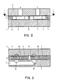
- valve housing 1 to 3 is a 4/2-way valve and comprises a valve housing 1 with an upper housing part 2 and a lower housing part 3. Between the upper housing part 2 and the lower housing part 3 is an intermediate plate 4 with an eyeglass-shaped seat for two switching disks 6 and 7 arranged.
- the upper housing part 2, the lower housing part 3 and the intermediate plate 4 are provided with seals, not shown, and connected to one another by screws and centering pins, also not shown.
- the switching disks 6 and 7 are arranged in the sealed valve housing 1 with play. Both switching disks 6, 7 each have two switching bores 8 and 9 or 10 and 11, which are arranged axially in the switching disks 6, 7. Only one or more switching bores per switching disk could also be provided.
- the switching bores 8 and 9 or 10 and 11 are connected to a slot 12 or 13 which is guided over the center of the switching disks 6, 7. On their circumference, the switching disks 6, 7 are provided with involute teeth 14 and 15, respectively.
- an axial inlet bore P is arranged above the center of the switching disc 6 and an axial return bore T is arranged above the center of the switching disc 7.
- axial bores 16, 17, 18 and 19 are incorporated in the upper housing part 2 and in the lower housing part 3.
- the bores 16 and 17 are located in the area of the switching disk 6 shown on the left in the drawings and the bores 18 and 19 are located in the area of the switching disk 7 shown on the right in the drawings.
- the axial bores 16 and 18 are horizontal in the lower part 3 of the housing Channel A and the axial bores 17 and 19 are each connected to one another by a horizontal channel B also provided in the lower housing part 3.
- the vertical bores 16, 17, 18 and 19 start from the respective horizontal channel A and B and are provided both in the lower housing part 3 and in the upper housing part 2.
- the vertical bores 16, 17, 18 and 19 end blind, wherein they have the same diameter as the sections running in the lower housing part 3 and are flush with them.
- the blindly ending sections of the bores 16, 17, 18 and 19 bring about pressure equalization.
- axial pressure compensation bores 20 are also left free. These are arranged in each switching disk 6, 7 in two rows parallel to the slots 12 and 13. Each switching disk 6 and 7 has a total of six axial pressure compensation bores 20. If the switching bores 8 and 9 in the switching disks 6 and 7 are located outside the area of the vertical bores 16, 17, 18 and 19 provided in the housing 1, at least one pressure compensation bore 20 is provided in the area of the vertical bores 16, 17, 18 and 19, whereby the partial sections of the bores located in the upper housing part 2 and in the lower housing part 3 are connected to one another.
- the drive medium for the rotary drive is supplied and carried away via two bores Z1 and Z2 provided in the upper housing part 2.
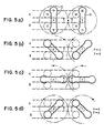
- FIG. 4 shows the position of a switching bore 8, 10 relative to an axial bore 16, 18 cooperating with it.
- the axial bore 16, 18 is shown in dashed lines.
- Below devon the upper half of the switching bore 8, 10 together with the subsequent radial slot 12, 13 is shown fully extended. In this position there is just yet no connection between the switching bore 8, 10 and the vertical bore 16, 18.
- the switching bore 8, 10 gets more and more into the area of the axial bore 16, 18 until it is aligned with it after pivoting through 45 °. After a swivel path of 90 ° clockwise, the connection is interrupted again.
- the switching bore 8, 10 is then in the position shown in broken lines in FIG. 4.
- FIGS. 5a, 5b, 5c and 5d four different positions of the switching disks with the switching bores 8, 9, 10 and 11 are shown.
- the slots 12 and 13 are each in a different position.
- the inlet bore P and the return bore T are not connected to the consumer channels A and B.
- the inlet bore P is connected to the channel A via the left switching disc and the return bore T is connected to the channel B via the right switching disc.
- the inlet bore P is connected to the channel B via the left switching disc and the return bore T is connected to the channel A via the right switching disc.
- the working medium for the rotary drive of the rotary slide valve enters through one of the bores Z1 or Z2 into the area of the toothings 14, 15 of the two switching disks 6, 7 and flows back through the other bore Z1, Z2 to a container located outside the rotary slide valve.
- the speed of the switching discs 6 and 7 depends on the flow rate of the drive medium and can be influenced from the outside. Both switching disks 6 and 7 rotate synchronously as a result of the toothing 14 and 15 attached to their circumference, the switching bores 8, 9, 10 and 11 in the switching disks 6 and 7 the bores 16, 17 located in the upper housing part 2 and in the lower housing part 3, Roam 18 and 19.
- the points drawn in bold in FIGS. 5a to 5d represent any two points on the circumference of the respective switching disk and illustrate the synchronous rotary movement of the switching disks under the influence of the rotary drive.
- the slots 12 and 13 in the switching disks 6 and 7 each connect both switching bores 8 and 9 or 10 and 11 provided in the disks permanently with the inlet bore P for the working medium or with the return bore T. With a full revolution of the switching disks 6 and 7 there are two switching cycles.
- the working pressure supplied is completely balanced axially and radially in each switching disc. All active surfaces are symmetrical, the pressure from both sides being compensated for by the pressure compensation holes 20 in the switching disks 6 and 7 during the closing process in the switching bores.
- each switching disk 6 and 7 is equipped with a hollow bearing journal 21 or 22, which transmits the radial forces to bearing bushes 23 and 24 provided in the upper housing part 2 and in the lower housing part 3.
- the radial forces can be largely reduced by means of relief grooves 25 and relief channels 26 shown in FIG. 7, which are provided in the intermediate plate 4.
- only one switching bore is provided for each switching disk, in which case the slot in the switching disk connecting the switching bore with the inlet bore or with the return bore in the valve housing can be formed only on one side.
- the channels A and B provided in the lower housing part 3 are connected to lines which lead to a vibration cylinder, where alternately one side of the piston and then the other side of the piston are pressurized.
Landscapes
- Engineering & Computer Science (AREA)
- Chemical & Material Sciences (AREA)
- Analytical Chemistry (AREA)
- Physics & Mathematics (AREA)
- Fluid Mechanics (AREA)
- Mechanical Engineering (AREA)
- General Engineering & Computer Science (AREA)
- Multiple-Way Valves (AREA)
- Fluid-Driven Valves (AREA)
Abstract
Description
Die Erfindung bezieht sich auf ein Drehschieberventil mit hydraulischem Drehantrieb, das ein Ventilgehäuse mit Bohrungen zur Zu- und Wegführung eines Arbeitsmediums und mindestens einen Verbraucherkanal aufweist, wobei der Verbraucherkanal abwechselnd mit den Bohrungen zur Zu- und Wegführung des Arbeitsmediums verbindbar ist.The invention relates to a rotary slide valve with a hydraulic rotary drive, which has a valve housing with bores for supplying and carrying away a working medium and at least one consumer channel, the consumer channel being able to be connected alternately with the bores for supplying and carrying away the working medium.
Ein solches Drehschieberventil ist aus der US-A-2 807 141 bekannt. Die bekannte Ausführung besteht aus einem länglichen Gehäuse mit einer Axialbohrung, in der eine als Drehschieber ausgebildete Welle gelagert ist. In axialem Abstand voneinander sind in der Welle zwei einander rechtwinkelig kreuzende - Durchgangsbohrungen vorgesehen, von denen die eine die Verbindung der Bohrung für die Zuführung des Arbeitsmediums und die andere die Verbindung der Bohrung zur Wegführung des Arbeitsmediums mit dem gegabelt ausgebildeten Verbraucherkanal steuert. Für den Antrieb des Drehschieberventils ist eine Turbine vorgesehen, deren Turbinenrad auf einem Ende der Welle befestigt und über eine Düse mit unter Druck stehendem Antriebsmedium beaufschlagt ist. Es handelt sich um einen Pulsator, der insbesondere für ein hydraulisches Bremssystem bestimmt ist, wo er einen pulsierenden Bremsdruck zur Verbesserung der Bremswirkung hervorrufen soll. Nachteilig ist dabei, daß die bekannte Ausführung verhältnismäßig groß, insbesondere lang und sperrig ist, wodurch der Einbau in hydraulische Geräte schon aus räumlichen Gründen schwierig ist. In funktioneller Hinsicht können die Bohrungen für das Arbeitsmedium mittels des rohrförmigen Drehschiebers nur schwer abgedichtet werden. Weiterhin ist die einseitige Druckbeaufschlagung der rotierenden Welle durch das Arbeitsmedium nachteilig.Such a rotary slide valve is known from US-A-2 807 141. The known embodiment consists of an elongated housing with an axial bore in which a shaft designed as a rotary slide valve is mounted. At an axial distance from each other two through holes intersecting at right angles are provided in the shaft, one of which controls the connection of the hole for the supply of the working medium and the other controls the connection of the hole for guiding the working medium away from the forked consumer channel. A turbine is provided for driving the rotary slide valve, the turbine wheel of which is attached to one end of the shaft and pressurized drive medium is applied via a nozzle. It is a pulsator which is intended in particular for a hydraulic brake system where it is intended to produce a pulsating brake pressure in order to improve the braking effect. The disadvantage here is that the known design is relatively large, in particular long and bulky, which makes installation in hydraulic devices difficult for spatial reasons alone. From a functional point of view, the holes for the working medium can only be sealed with difficulty using the tubular rotary valve. Furthermore, the one-sided pressurization of the rotating shaft by the working medium is disadvantageous.
Der Erfindung liegt die Aufgabe zugrunde, ein Drehschieberventil der angeführten Bauart zu schaffen, das ein kompaktes Gehäuse aufweist und gegen mechanische Beanspruchungen unempfindlich ist, so daß es sich für den Einbau in hydraulische Geräte besonders eignet, wobei auch eine sichere Abdichtung einfach möglich sein soll.The invention has for its object to provide a rotary slide valve of the type mentioned, which has a compact housing and is insensitive to mechanical stresses, so that it is particularly suitable for installation in hydraulic devices, with a secure seal should be easily possible.
Mit der Erfindung wird diese Aufgabe dadurch gelöst, daß zwei Schaltscheiben vorgesehen sind, die an ihrem Umfang mit Verzahnungen versehen sind, welche in ständigem Eingriff miteinander stehen, daß die Schaltscheiben mit mindestens je einer axialen Schaltbohrung versehen sind, die bei Drehung der Schaltscheiben abwechselnd mit dem Verbraucherkanal verbindbar sind, und daß in jeder Schaltscheibe ein sich radial erstreckender Schlitz vorgesehen ist, der die Schaltbohrung der einen Schaltscheibe ständig mit der Bohrung zur Zuführung des Arbeitsmediums und die Schaltbohrung der anderen Schaltscheibe ständig mit der Bohrung zur Wegführung des Arbeitsmediums verbindet. Durch die Verwendung von Schaltscheiben für die Steuerung des Arbeitsmediums ergibt sich nicht nur ein flaches Ventilgehäuse, sondern es sind auch die erforderlichen Bohrungen für die Zu-und Wegführung des Arbeitsmediums und die Verbraucherkanäle einfach auszubilden, ohne daß freiliegende Leitungen erforderlich sind. Die Schaltbohrungen in den Schaltscheiben münden in ebenen Flächen, so daß die Abdichtung entsprechend einfach ist. Darüber hinaus zeichnet sich das erfindungsgemäße Drehschieberventil durch Robustheit, insbesondere durch Widerstandsfähigkeit gegen mechanische Einwirkungen von außen, sowie durch einfache Herstellbarkeit aus.With the invention, this object is achieved in that two switching disks are provided, which are provided on their circumference with toothings which are in constant engagement with one another, that the switching disks are provided with at least one axial switching bore, which alternately with rotation of the switching disks the consumer channel can be connected, and that in each switching disc a radially extending slot is provided which constantly connects the switching bore of the one switching disc with the bore for supplying the working medium and the switching bore of the other switching disc with the bore for guiding the working medium away. The use of switching disks for the control of the working medium not only results in a flat valve housing, but also the bores required for the supply and removal of the working medium and the consumer ducts can be easily formed without the need for exposed lines. The switching holes in the switching disks open into flat surfaces, so that the sealing is correspondingly simple. In addition, the rotary slide valve according to the invention is characterized by robustness, in particular by resistance to external mechanical influences, and by simple manufacture.
Vorteilhaft können im Rahmen der Erfindung pro Schaltscheibe zwei symmetrisch zur Mitte angeordnete Schaltbohrungen vorgesehen sein, die mit dem Schlitz verbunden sind. Gegenüber einer Ausführung mit nur einer Schaltbohrung je Schaltscheibe kann dadurch bei gleichbleibender Pulsanzahl die Umlaufgeschwindigkeit der Scheiben auf die Hälfte verringert werden.Within the scope of the invention, two switching bores which are arranged symmetrically to the center and which are connected to the slot can advantageously be provided per switching disk. Compared to a version with only one switching hole per switching disc, the rotating speed of the discs can be reduced by half while the number of pulses remains the same.
Wenn das Gehäuse einen Gehäuseoberteil und einen Gehäuseunterteil und eine zwischen denselben angeordnete Zwischenplatte zur Aufnahme der Schaltscheiben aufweist, kann es besonders einfach hergestellt und montiert werden.If the housing has an upper housing part and a lower housing part and an intermediate plate arranged between them for receiving the switching disks, it can be manufactured and assembled particularly easily.
Erfindungsgemäß können die Schaltscheiben mit Druckausgleichsbohrungen versehen sein, die sie parallel zu den Schaltbohrungen in seitlichem Abstand von diesen axial durchsetzen. Es werden dadurch einseitige Druckbelastungen der Schaltscheiben durch das Arbeitsmedium und damit verbundene höhere Reibungskräfte vermieden.According to the invention, the switching disks can be provided with pressure compensation bores, which they axially penetrate parallel to the switching bores at a lateral distance from them. This avoids one-sided pressure loads on the switching disks caused by the working medium and the associated higher frictional forces.
Eine bevorzugte Ausführung des erfindungsgemäßen Drehschieberventils besteht darin, daß der Drehantrieb von den Verzahnungen der Schaltscheiben gebildet ist und im Ventilgehäuse Bohrungen zur Zu- und Wegführung eines Antriebsmediums zur Betätigung des Drehantriebs vorgesehen sind. Dabei werden also die Schaltscheiben selbst zugleich als Drehantrieb verwendet, so daß weitere Konstruktionsmaßnahmen hiefür, wegfallen können..A preferred embodiment of the rotary slide valve according to the invention consists in the fact that the rotary drive is formed by the toothing of the switching disks and bores are provided in the valve housing for supplying and removing a drive medium for actuating the rotary drive. The switch disks themselves are also used as rotary actuators, so that further design measures for them can be omitted.
Zur Erhöhung der Robustheit des. erfindungsgemäßen Drehschieberventils hat es sich ferner als vorteilhaft erwiesen, mit den Schaltscheiben verbundene Lagerzapfen und im Gehäuse Lagerbuchsen vorzusehen.To increase the robustness of the rotary slide valve according to the invention, it has also proven to be advantageous to provide bearing journals connected to the switching disks and bearing bushes in the housing.
Die Drehbewegung der Schaltscheiben kann gemäß der Erfindung dadurch weiter verbessert und erleichtert werden daß in den Randbereichen der Schaltscheiben, die den Randbereichen welche vom zu- oder weggeführten Antriebsmedium zur Betätigung des Drehantriebs beaufschlagt sind, auf derselben Schaltscheibe diametral gegenüberliegen, Entlastungsnuten vorgesehen sind, die über Entlastungskanäle mit den vom Antriebsmedium beaufschlagten Randbereichen in Verbindung stehen. Es werden dadurch auch in radialer Richtung wirkende einseitige Druckbeaufschlagungen der Schaltscheiben vermieden.The rotary movement of the switching disks can be further improved and facilitated according to the invention in that in the edge areas of the switching disks, which are diametrically opposed to the edge areas which are acted upon by the supply or removal of drive medium for actuating the rotary drive, diametrically opposite relief grooves are provided, which are provided via Relief channels are connected to the edge areas exposed to the drive medium. It will this also avoids one-sided pressurization of the switching disks acting in the radial direction.
Das erfindungsgemäße Drehschieberventil ist aufgrund seiner kompakten Bauweise, seiner mechanischen Unempfindlichkeit und aufgrund der hohen erzielbaren Schaltfrequenzen mit besonderem Vorteil für eine hydraulische Vibroramme geeignet.The rotary slide valve according to the invention is particularly suitable for a hydraulic vibrating ram due to its compact design, its mechanical insensitivity and due to the high switching frequencies that can be achieved.
In den Zeichnungen sind Ausführungsbeispiele des erfindungsgemäßen Drehschieberventils dargestellt, die nachfolgend beschrieben sind. Es zeigen:
- Fig. 1 ein Ausführungsbeispiel der Erfindung im Querschnitt nach der Linie I-I in Fig. 2,
- Fig. 2 einen Axialschnitt nach der Linie 11-11 in Fig. 1,
- Fig. 3 einen Schnitt nach der Linie 111-111 in Fig. 1,
- Fig. 4 zwei verschiedene Lagen einer Schaltbohrung in der Schaltscheibe bezüglich der Bohrung im Ventilgehäuse,
- Fig. 5 a-d vier verschiedene Stellungen der beiden Schaltschiltze in den Schaltscheiben in schematischer Darstellung,
- Fig. 6 einen Schnitt nach der Linie VI-VI in Fig. 7 durch ein weiteres Ausführungsbeispiel der Erfindung und
- Fig. 7 eine Draufsicht auf das Ventilgehäuse des Ausführungsbeispiels nach Fig. 6 mit abgenommenem Gehäuseoberteil.
- 1 shows an embodiment of the invention in cross section along the line II in Fig. 2,
- 2 shows an axial section along the line 11-11 in FIG. 1,
- 3 shows a section along the line 111-111 in FIG. 1,
- 4 shows two different positions of a switching hole in the switching disk with respect to the hole in the valve housing,
- 5 ad four different positions of the two switching contacts in the switching disks in a schematic representation,
- Fig. 6 shows a section along the line VI-VI in Fig. 7 by a further embodiment of the invention and
- Fig. 7 is a plan view of the valve housing of the embodiment of FIG. 6 with the upper housing part removed.
Das in den Fig. 1 bis 3 dargestellte Drehschieberventil ist ein 4/2-Wegeventil und umfaßt ein Ventilgehäuse 1 mit einem Gehäuseoberteil 2 und einem Gehäuseunterteil 3. Zwischen dem Gehäuseoberteil 2 und dem Gehäuseunterteil 3 ist eine Zwischenplatte 4 mit einem brillenförmigen Sitz für zwei Schaltscheiben 6 und 7 angeordnet. Der Gehäuseoberteil 2, der Gehäuseunterteil 3 und die Zwischenplatte 4 sind mit nicht dargestellten Dichtungen versehen und durch ebenfalls nicht dargestellte Schrauben und Zentrierstifte miteinander verbunden. Die Schaltscheiben 6 und 7 sind im dichten Ventilgehäuse 1 mit Spiel angeordnet. Beide Schaltscheiben 6, 7 weisen je zwei Schaltbohrungen 8 und 9 bzw. 10 und 11 auf, die in den Schaltscheiben 6, 7 axial angeordnet sind. Es könnten auch nur eine oder aber mehrere Schaltbohrungen pro Schaltscheibe vorgesehen sein. Die Schaltbohrungen 8 und 9 bzw. 10 und 11 sind mit einem über die Mitte der Schaltscheiben 6,7 geführten Schlitz 12 bzw. 13 verbunden. An ihrem Umfang sind die Schaltscheiben 6, 7 mit einer Evolventen-Verzahnung 14 bzw. 15 versehen.1 to 3 is a 4/2-way valve and comprises a
Im Gehäuseoberteil 2 ist über der Mitte der Schaltscheibe 6 eine axiale Zulaufbohrung P und über der Mitte der Schaltscheibe 7 eine axiale Rücklaufbohrung T angeordnet. In gleichem radialem Abstand von der Mitte der Schaltscheiben 6, 7 wie die in diesen vorgesehenen Schaltbohrungen 8, 9, 10 und 11 sind im Gehäuseoberteil 2 und im Gehäuseunterteil 3 axiale Bohrungen 16, 17, 18 und 19 eingearbeitet. Die Bohrungen 16 und 17 befinden sich im Bereich der in den Zeichnungen links dargestellten Schaltscheibe 6 und die Bohrungen 18 und 19 befinden sich im Bereich der in den Zeichnungen rechts dargestellten Schaltscheibe 7. Die axialen Bohrungen 16 und 18 sind durch einen im Gehäuseunterteil 3 verlaufenden horizontalen Kanal A und die axialen Bohrungen 17 und 19 durch einen ebenfalls im Gehäuseunterteil 3 vorgesehenen horizontalen Kanal B jeweils miteinander verbunden. Die vertikalen Bohrungen 16, 17, 18 und 19 gehen vom jeweiligen horizontalen Kanal A bzw. B aus und sind sowohl im Gehäuseunterteil 3 als auch im Gehäuseoberteil 2 vorgesehen. Im Gehäuseoberteil 2 enden die vertikalen Bohrungen 16, 17, 18 und 19 blind, wobei sie den gleichen Durchmesser wie die im Gehäuseunterteil 3 verlaufenden Abschnitte aufweisen und mit diesen fluchten. Die blind endenden Abschnitte der Bohrungen 16, 17, 18 und 19 bewirken einen Druckausgleich.In the
In den Schaltscheiben 6 und 7 sind weiterhin axiale Druckausgleichsbohrungen 20 ausgespart. Diese sind in jeder Schaltscheibe 6, 7 in je zwei zu den Schlitzen 12 und 13 parallelen Reihen angeordnet. Jede Schaltscheibe 6 und 7 weist insgesamt sechs axiale Druckausgleichsbohrungen 20 auf. Wenn die Schaltbohrungen 8 und 9 in den Schaltscheiben 6 und 7 sich außerhalb des Bereichs der im Gehäuse 1 vorgesehenen vertikalen Bohrungen 16, 17, 18 und 19 befinden, kom mit jeweils wenigstens eine Druckausgleichsbohrung 20 in den Bereich der vertikalen Bohrungen 16, 17, 18 und 19, wodurch die im Gehäuseoberteil 2 und im Gehäuseunterteil 3 befindlichen Teilabschnitte der Bohrungen miteinander verbunden sind. Über zwei im Gehäuseoberteil 2 vorgesehene Bohrungen Z1 und Z2 wird das Antriebsmedium für den Drehantrieb zugeführt und weggeführt.In the
In Fig. 4 ist die Lage einer Schaltbohrung 8, 10 relativ zu einer mit ihr zusammenwirkenden axialen Bohrung 16, 18 dargestellt. Die axiale Bohrung 16, 18 ist gestrichelt eingezeichnet. Unterhalb devon ist die obere Hälfte der Schaltbohrung 8, 10 zusammen mit dem anschließenden radialen Schlitz 12, 13 voll ausgezogen dargestellt. In dieser Stellung besteht gerade noch keine Verbindung zwischen der Schaltbohrung 8, 10 und der vertikalen Bohrung 16, 18. Wenn die zugehörige Schaltscheibe, die in Fig. 4 nicht dargestellt ist, im Uhrzeigersinn gedreht wird, gelangt die Schaltbohrung 8, 10 immer mehr in den Bereich der axialen Bohrung 16, 18, bis sie nach Verschwenkung um 45° mit dieser fluchtet. Nach einem Schwenkweg von insgesamt 90° im Uhrzeigersinn wird die Verbindung wieder unterbrochen. Die Schaltbohrung 8, 10 befindet sich dann in der in Fig. 4 strichpunktiert eingezeichneten Stellung.4 shows the position of a
In den Fig. 5a, 5b, 5c und 5d sind vier verschiedene Stellungen der Schaltscheiben mit den Schaltbohrungen 8, 9, 10 und 11 dargestelit. Die Schlitze 12 und 13 befinden sich dabei jeweils in einer anderen Lage. In den Stellungen nach den Fig. 5a und 5c sind die Zulaufbohrung P und die Rücklaufbohrung T mit den Verbraucherkanälen A und B nicht verbunden. In der Stellung nach Fig. 5b ist die Zulaufbohrung P über die linke Schaltscheibe mit dem Kanal A und die Rücklaufbohrung T über die rechte Schaltscheibe mit dem Kanal B verbunden. In der Stellung nach Fig. 5d ist dagegen die Zulaufbohrung P über die linke Schaltscheibe mit dem Kanal B und die Rücklaufbohrung T über die rechte Schaltscheibe mit dem Kanal A verbunden.5a, 5b, 5c and 5d, four different positions of the switching disks with the switching bores 8, 9, 10 and 11 are shown. The
Das Arbeitsmedium für den Drehantrieb des Drehschieberventils tritt durch eine der Bohrungen Z1 oder Z2 in den Bereich der Verzahnungen 14, 15 der beiden Schaltscheiben 6, 7 ein und fließt durch die andere Bohrung Z1, Z2 zu einem außerhalb des Drehschieberventils befindlichen Behälter zurück. Die Drehzahl der Schaltscheiben 6 und 7 ist von der Durchflußmenge des Antriebsmediums abhängig und kann von außen beeinflußt werden. Beide Schaltscheiben 6 und 7 drehen sich in Folge der an ihrem Umfang angebrachten Verzahnungen 14 und 15 synchron, wobei die Schaltbohrungen 8, 9, 10 und 11 in den Schaltscheiben 6 und 7 die im Gehäuseoberteil 2 und im Gehäuseunterteil 3 befindlichen Bohrungen 16, 17, 18 und 19 durchstreifen.The working medium for the rotary drive of the rotary slide valve enters through one of the bores Z1 or Z2 into the area of the
Die in den Fig. 5a bis 5d fett eingezeichneten Punkte stellen zwei beliebige Punkte am Umfang der jeweiligen Schaltscheibe dar und verdeutlichen die synchrone Drehbewegung der Schaltscheiben unter dem Einfluß des Drehantriebs. Die Schlitze 12 und 13 in den Schaltscheiben 6 und 7 verbinden je beide in den Scheiben vorgesehenen Schaltbohrungen 8 und 9 bzw. 10 und 11 permanent mit der Zulaufbohrung P für das Arbeitsmedium bzw. mit der Rücklaufbohrung T. Bei einer vollen Umdrehung der Schaltscheiben 6 und 7 ergeben sich zwei Schaltzyklen. Der zugeführte Arbeitsdruck ist in jeder Schaltscheibe axial und radial völlig ausgeglichen. Alle Wirkflächen sind symmetrisch, wobei während des Schließvorganges in den Schaltbohrungen der Druck von beiden Seiten durch die Druckausgleichsbohrungen 20 in den Schaltscheiben 6 und 7 ausgeglichen wird. Damit wird vermieden, daß die Schaltscheiben 6, 7 gegen den Gehäuseoberteil 2 gedrückt werden, wenn eine oder mehrere der Bohrungen 16, 17, 18,19 im Ventilgehäuse 1 durch die Schaltscheiben 6, verschlossen werden. Radiale Kräfte, die durch den Druck des Antriebsmediums erzeugt werden, können über die von den Spitzen der Verzahnung 14, 15 gebildete Lauffläche auf die Zwischenplatte 4 übertragen werden.The points drawn in bold in FIGS. 5a to 5d represent any two points on the circumference of the respective switching disk and illustrate the synchronous rotary movement of the switching disks under the influence of the rotary drive. The
In den Fig. 6 und 7 ist ein weiteres Ausführungsbeispiel der Erfindung dargestellt. Im Gegensatz zum Ausführungsbeispiel nach den Fig. 1 bis 3 ist jede Schaltscheibe 6 und 7 mit einem hohlen Lagerzapfen 21 bzw. 22 ausgestattet, der die Radialkräfte auf im Gehäuseoberteil 2 und im Gehäuseunterteil 3 vorgesehene Lagerbuchsen 23 und 24 überträgt. Die Radialkräfte können durch in Fig. 7 dargestellte Entlastungsnuten 25 und Entlastungskanäle 26, die in der Zwischenplatte 4 vorgesehen sind, weitgehend reduziert werden.6 and 7 a further embodiment of the invention is shown. In contrast to the exemplary embodiment according to FIGS. 1 to 3, each
Bei einer weiteren, nicht dargestellten Ausführungsform ist je Schaltscheibe nur eine Schaltbohrung vorgesehen, wobei dann der die Schaltbohrung mit der Zulaufbohrung bzw. mit der Rücklaufbohrung im Ventilgehäuse verbindende Schlitz in der Schaltscheibe nur einseitig ausgebildet werden kann.In a further embodiment, not shown, only one switching bore is provided for each switching disk, in which case the slot in the switching disk connecting the switching bore with the inlet bore or with the return bore in the valve housing can be formed only on one side.
Bei der Verwendung des beschriebenen Drehschieberventils bei einer Vibroramme werden die im Gehäuseunterteil 3 vorgesehenen Kanäle A und B an Leitungen angeschlossen, die zu einem Schwingungszylinder führen, wo abwechselnd einmal die eine, dann die andere Kolbenseite mit Druck beaufschlagt wird.When using the rotary slide valve described with a vibrating ram, the channels A and B provided in the
Claims (8)
Priority Applications (1)
| Application Number | Priority Date | Filing Date | Title |
|---|---|---|---|
| AT85890104T ATE32624T1 (en) | 1984-05-11 | 1985-05-03 | DIRECTIONAL VALVE WITH HYDRAULIC ACTUATION. |
Applications Claiming Priority (2)
| Application Number | Priority Date | Filing Date | Title |
|---|---|---|---|
| CH2356/84A CH666091A5 (en) | 1984-05-11 | 1984-05-11 | ROTARY VALVE WITH HYDRAULIC ROTARY DRIVE. |
| CH2356/84 | 1984-05-11 |
Publications (2)
| Publication Number | Publication Date |
|---|---|
| EP0161237A1 EP0161237A1 (en) | 1985-11-13 |
| EP0161237B1 true EP0161237B1 (en) | 1988-02-24 |
Family
ID=4231874
Family Applications (1)
| Application Number | Title | Priority Date | Filing Date |
|---|---|---|---|
| EP85890104A Expired EP0161237B1 (en) | 1984-05-11 | 1985-05-03 | Hydraulically-operated directional-control valve |
Country Status (5)
| Country | Link |
|---|---|
| US (1) | US4633903A (en) |
| EP (1) | EP0161237B1 (en) |
| AT (1) | ATE32624T1 (en) |
| CH (1) | CH666091A5 (en) |
| DE (1) | DE3561671D1 (en) |
Families Citing this family (3)
| Publication number | Priority date | Publication date | Assignee | Title |
|---|---|---|---|---|
| US5241733A (en) * | 1991-09-10 | 1993-09-07 | Geber Garment Technology, Inc. | Method of making a cloth cutter bristle bed from elongate support members |
| FR2685944B1 (en) * | 1992-01-08 | 1995-05-19 | Snecma | ROTARY FLUID DELIVERY VALVE AND VALVE ASSEMBLY USING THE SAME. |
| WO2022117143A1 (en) * | 2020-12-01 | 2022-06-09 | Hanon Systems Efp Deutschland Gmbh | Device for controlling a flow and distributing a fluid in a fluid circuit, and conveying unit having said device |
Family Cites Families (11)
| Publication number | Priority date | Publication date | Assignee | Title |
|---|---|---|---|---|
| GB298935A (en) * | 1927-07-14 | 1928-10-15 | Arthur Treve Holman | Improvements in or relating to fluid-actuated rock-drills and similar tools |
| US2178182A (en) * | 1939-03-31 | 1939-10-31 | Harry F Morgan | Valve structure |
| US2807141A (en) * | 1953-06-02 | 1957-09-24 | Don S Strader | Pulsator for a hydraulic system |
| US2837115A (en) * | 1956-10-09 | 1958-06-03 | Howard S Bancroft | Fluid pressure controlling valve |
| US3296874A (en) * | 1964-12-16 | 1967-01-10 | Gen Motors Corp | Vibration generator |
| US3499465A (en) * | 1967-02-08 | 1970-03-10 | Maurice Rhodes Zent | Milking machines |
| US3654961A (en) * | 1969-03-14 | 1972-04-11 | Albert Phillips | Rotary percussion drill having a hydraulically actuated percussion device |
| GB1316261A (en) * | 1969-06-27 | 1973-05-09 | Howard Ltd C A E C | Fluid flow control valves |
| DE2819404A1 (en) * | 1978-05-03 | 1979-11-08 | Wildfang Dieter Kg | LIQUID PULSE GENERATOR |
| US4373874A (en) * | 1979-07-30 | 1983-02-15 | Albert Phillips | Fluid actuated pump system |
| US4478248A (en) * | 1983-01-20 | 1984-10-23 | Devall Donald L | Rotary valve |
-
1984
- 1984-05-11 CH CH2356/84A patent/CH666091A5/en not_active IP Right Cessation
-
1985
- 1985-05-03 DE DE8585890104T patent/DE3561671D1/en not_active Expired
- 1985-05-03 AT AT85890104T patent/ATE32624T1/en not_active IP Right Cessation
- 1985-05-03 EP EP85890104A patent/EP0161237B1/en not_active Expired
- 1985-05-10 US US06/732,724 patent/US4633903A/en not_active Expired - Fee Related
Also Published As
| Publication number | Publication date |
|---|---|
| ATE32624T1 (en) | 1988-03-15 |
| CH666091A5 (en) | 1988-06-30 |
| DE3561671D1 (en) | 1988-03-31 |
| US4633903A (en) | 1987-01-06 |
| EP0161237A1 (en) | 1985-11-13 |
Similar Documents
| Publication | Publication Date | Title |
|---|---|---|
| DE2753185C2 (en) | Control valve, in particular for power steering | |
| DE1601835B2 (en) | ROTARY PISTON MACHINE WITH ROTARY VALVE CONTROLLER USED AS A PUMP OR LIQUID MOTOR | |
| EP0080670A1 (en) | Rotation device for suspended loads | |
| EP0161237B1 (en) | Hydraulically-operated directional-control valve | |
| DE3544857C2 (en) | Internal gear machine | |
| AT390313B (en) | PISTON VALVE | |
| DE3837373C2 (en) | Device for continuous unbalance compensation on a rotor, in particular a grinding wheel | |
| DE7932853U1 (en) | REVOLVING CLAMPING CYLINDER WITH CLAMPING PISTON FOR CLAMPING DEVICES ON MACHINE TOOLS | |
| DE3930334C1 (en) | ||
| DE522341C (en) | Rotary lobe pump with sickle-shaped working chamber and pistons with radial ribs that can be moved in the piston drum and absorb the loads on the pistons | |
| DE10028336C1 (en) | Engine with axial piston has through guide channel between at least one tooth crown surface and tooth space bottom opposite it | |
| DE3936325C2 (en) | ||
| DE1811268C3 (en) | Hydraulic power steering device | |
| DE3124611A1 (en) | "COMPENSATING OR COMPENSATING DEVICE FOR A PRESSURE-LIQUID DEVICE HAVING TWO MOVING ORGANS AND APPLICATIONS OF THE DEVICE, ESPECIALLY THE APPLICATION FOR A STEERING TRAIN (LENGTH) (LENGTH)" | |
| DE2812906C2 (en) | Hydrostatic power steering for vehicles | |
| DE1703380C3 (en) | Rotary piston engine | |
| DE29905480U1 (en) | Multiple swivel connector for connecting a fluid operated tool to a fluid source | |
| DE483082C (en) | Piston control for rotary piston machines, especially hydraulic ones, with pistons that can be moved radially in the piston drum | |
| DE1194709B (en) | Rotary servo motor, especially for adjusting the guide vanes of water turbines | |
| DE2134944C3 (en) | Piston engine | |
| DE962060C (en) | Hydrostatic rotary piston machine for driving vehicles | |
| DE1600808C (en) | Actuating device operated by pressure medium for the drive shaft of a valve | |
| DE2852477C2 (en) | Rotary piston machine | |
| DE3028485A1 (en) | Isolating gate valve with ceramic slide - has ceramic seat in form of orifice plate with metallic backing plate | |
| DE2150041A1 (en) | ROTATING CLAMPING CYLINDER FOR CLAMPING DEVICES ON MACHINE TOOLS |
Legal Events
| Date | Code | Title | Description |
|---|---|---|---|
| PUAI | Public reference made under article 153(3) epc to a published international application that has entered the european phase |
Free format text: ORIGINAL CODE: 0009012 |
|
| AK | Designated contracting states |
Designated state(s): AT DE FR NL |
|
| 17P | Request for examination filed |
Effective date: 19860321 |
|
| 17Q | First examination report despatched |
Effective date: 19861128 |
|
| GRAA | (expected) grant |
Free format text: ORIGINAL CODE: 0009210 |
|
| AK | Designated contracting states |
Kind code of ref document: B1 Designated state(s): AT DE FR NL |
|
| REF | Corresponds to: |
Ref document number: 32624 Country of ref document: AT Date of ref document: 19880315 Kind code of ref document: T |
|
| REF | Corresponds to: |
Ref document number: 3561671 Country of ref document: DE Date of ref document: 19880331 |
|
| ET | Fr: translation filed | ||
| PLBE | No opposition filed within time limit |
Free format text: ORIGINAL CODE: 0009261 |
|
| STAA | Information on the status of an ep patent application or granted ep patent |
Free format text: STATUS: NO OPPOSITION FILED WITHIN TIME LIMIT |
|
| 26N | No opposition filed | ||
| REG | Reference to a national code |
Ref country code: FR Ref legal event code: TP |
|
| NLS | Nl: assignments of ep-patents |
Owner name: HOERBIGER VENTILWERKE AKTIENGESELLSCHAFT TE WENEN, |
|
| PGFP | Annual fee paid to national office [announced via postgrant information from national office to epo] |
Ref country code: FR Payment date: 19960424 Year of fee payment: 12 |
|
| PGFP | Annual fee paid to national office [announced via postgrant information from national office to epo] |
Ref country code: DE Payment date: 19960426 Year of fee payment: 12 |
|
| PGFP | Annual fee paid to national office [announced via postgrant information from national office to epo] |
Ref country code: AT Payment date: 19960524 Year of fee payment: 12 |
|
| PGFP | Annual fee paid to national office [announced via postgrant information from national office to epo] |
Ref country code: NL Payment date: 19960531 Year of fee payment: 12 |
|
| PG25 | Lapsed in a contracting state [announced via postgrant information from national office to epo] |
Ref country code: AT Effective date: 19970503 |
|
| PG25 | Lapsed in a contracting state [announced via postgrant information from national office to epo] |
Ref country code: NL Effective date: 19971201 |
|
| PG25 | Lapsed in a contracting state [announced via postgrant information from national office to epo] |
Ref country code: FR Free format text: LAPSE BECAUSE OF NON-PAYMENT OF DUE FEES Effective date: 19980130 |
|
| NLV4 | Nl: lapsed or anulled due to non-payment of the annual fee |
Effective date: 19971201 |
|
| PG25 | Lapsed in a contracting state [announced via postgrant information from national office to epo] |
Ref country code: DE Free format text: LAPSE BECAUSE OF NON-PAYMENT OF DUE FEES Effective date: 19980203 |
|
| REG | Reference to a national code |
Ref country code: FR Ref legal event code: ST |