EP0160954A1 - Winding machine - Google Patents
Winding machine Download PDFInfo
- Publication number
- EP0160954A1 EP0160954A1 EP85105473A EP85105473A EP0160954A1 EP 0160954 A1 EP0160954 A1 EP 0160954A1 EP 85105473 A EP85105473 A EP 85105473A EP 85105473 A EP85105473 A EP 85105473A EP 0160954 A1 EP0160954 A1 EP 0160954A1
- Authority
- EP
- European Patent Office
- Prior art keywords
- lever
- winding machine
- machine according
- support arm
- carriage
- Prior art date
- Legal status (The legal status is an assumption and is not a legal conclusion. Google has not performed a legal analysis and makes no representation as to the accuracy of the status listed.)
- Granted
Links
Images


Classifications
-
- B—PERFORMING OPERATIONS; TRANSPORTING
- B65—CONVEYING; PACKING; STORING; HANDLING THIN OR FILAMENTARY MATERIAL
- B65H—HANDLING THIN OR FILAMENTARY MATERIAL, e.g. SHEETS, WEBS, CABLES
- B65H54/00—Winding, coiling, or depositing filamentary material
- B65H54/02—Winding and traversing material on to reels, bobbins, tubes, or like package cores or formers
- B65H54/40—Arrangements for rotating packages
- B65H54/52—Drive contact pressure control, e.g. pressing arrangements
-
- B—PERFORMING OPERATIONS; TRANSPORTING
- B65—CONVEYING; PACKING; STORING; HANDLING THIN OR FILAMENTARY MATERIAL
- B65H—HANDLING THIN OR FILAMENTARY MATERIAL, e.g. SHEETS, WEBS, CABLES
- B65H2701/00—Handled material; Storage means
- B65H2701/30—Handled filamentary material
- B65H2701/31—Textiles threads or artificial strands of filaments
Definitions
- the invention relates to a winding machine for man-made fibers. It is used in particular for winding freshly spun and / or drawn multifilament threads in spinning machines.
- the winding machine has a traversing device and a winding spindle.
- the traversing device and the winding spindle are movably mounted relative to one another, e.g. the winding spindle is fixed in a frame and the traversing device is mounted in a movable carriage.
- Such a winding machine is shown in DE-OS 20 39 772, in which the traversing mechanism is mounted in a structural unit consisting of a slide and a cantilever arm attached to it.
- the carriage is essentially straight in a straight guide and is guided such that the traversing device can avoid the growing diameter of the bobbin formed on the bobbin.
- the weight of the unit consisting of the slide and the support arm is compensated for in whole or in part by a force transmitter which is designed as a pneumatic cylinder-piston unit in the known winding machine.
- the solution according to the invention is characterized in that the force transmitter does not act directly on the carriage, but rather by means of a one-armed or two-armed lever articulated in the frame of the winding machine in the central region of the support arm, preferably in the longitudinal center of gravity of the support arm. It is hereby avoided that the support arm and slide exert an impermissible bending moment on the guides and are themselves subjected to an impermissible bending moment.
- lever transmission ratio can be chosen so that despite a large range of movement of the slide, the support arm and the traversing, i.e. Despite the production of coils with a very large diameter, the length of movement of the force transmitter can be chosen to be smaller in the ratio of the lever transmission ratio, which is favorable for friction, wear and space utilization.
- the force transmitter preferably engages between the pivot point and the Longitudinal center of the pivot lever, while the end of the pivot lever rests on the support arm.
- the force transmitter engages at one end, while the other end rests on the support arm.
- the lever is designed with two arms and bent at its pivot point, so that despite the limited length of the frame of the winding machine, a sufficient length of the lever arm is provided for the force application of the force transmitter.
- the force transmitter used in the context of this invention is preferably a hydraulic or pneumatic cylinder-piston unit. This cylinder-piston unit is applied to a constant or variable pressure in the course of the winding cycle. As a result, part of the weight of the assembly consisting of slide, support arm, traversing, etc. is absorbed. It can thus be achieved that a drive roller, which is also mounted in the support arm, bears against the bobbins to be formed on the bobbin spindle with only a certain, predetermined pressure which may be variable in the course of the winding cycle.
- the guide used within the scope of this invention is a straight guide, e.g. in the form of a cylinder-roller guide, which is arranged in a fixed position in the frame and on which the slide slides.
- An embodiment with a particularly high stability of the assembly arm and carriage is achieved in that the assembly is guided in a straight line by two guides which are arranged at the ends of a diagonal of the carriage. This gives the guides their greatest possible distance.
- the point of engagement of the lever with respect to the support arm has a degree of freedom in the longitudinal direction.
- the free end and the support arm can lie on one another in a plain bearing.
- the support arm and the lever are connected by an intermediate lever which is articulated on the support arm on the one hand and on the lever on the other hand.
- the point of application of the lever is articulated to the support arm and that the lever itself is mounted with a degree of freedom in relation to its frame.
- the swivel joint of the lever can be mounted in a slide bearing.
- the force transmitter has a degree of freedom transverse to its direction of force relative to the lever.
- the power transmitter is pivotally mounted or the power transmitter and the lever are connected to one another by a hinged intermediate lever.
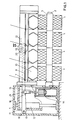
- the winding spindle 2 is mounted in a stationary and freely rotatable manner in the fixed frame 1.
- Sleeves 3 are attached to the winding spindle.
- a coil 4 is formed on each sleeve 3.
- the coils with the winding spindle are driven by the drive roller 5 (see FIG. 3).
- Changings 6 are used to move the threads back and forth.
- Each oscillation 6 consists of a thread guide 7, which is driven in a straight guide 8 by a reversing thread shaft 9, and of a grooved roller 10 therein recessed grooves (see. Fig. 3).
- any other traversing can be used, such as a so-called "wing traversing”.
- the drive roller and the traversing mechanism are mounted in a slide 11 and a support arm 12 attached thereto, the support arm 12 being attached to the slide 11 in a cantilever manner.
- the carriage 11 is movable in two straight guides 13 in the vertical direction. This ensures that the traversing and the drive roller can avoid the growing spool diameter.
- a force transmitter 14 is provided, in the illustrated case a cylinder-piston unit, as also by the prior art is known.
- the piston rod 15 engages via an intermediate lever 16 on a lever 17 which is mounted on one side on the frame 1 in the pivot point 18 and engages with its free end 19 on a slide bearing 20 of the support arm 12.
- the distance between the pivot point and the point 21 of the force application of the force transmitter 14 on the one hand and the end 19 of the support arm on the other hand is selected so that the slide or support arm at the predetermined stroke length of the force transmitter the stroke sufficient for the desired maximum coil diameter, which also allows the drive roller to be lifted off the spool surfaces.
- the slide bearing 20 is attached approximately in the longitudinal center of the support arm and approximately in the longitudinal center of gravity of the entire structural unit comprising the slide 11 and the support arm 12. It is not necessary for this longitudinal center of gravity to be adhered to exactly, since it can be assumed that the guides 13 will be able to do so anyway need to catch a certain moment. However, this design prevents the support arm from exerting an impermissibly high bending moment on the slide 11 and the guides 13.
- the slide bearing 20 serves to ensure the degree of freedom in the longitudinal direction of the support arm 12 required for the lever end 19 when the lever is pivoted about pivot bearing 18.
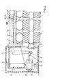
- Fig. 4 shows an alternative to the sliding bearing 20 that the end 19 is connected to the support arm 12 by an intermediate lever 22.
- the intermediate lever is articulated on the support arm 12 on the one hand and the end 19 of the lever 17 on the other hand and permits relative movement in the longitudinal direction of the support arm.
- the winding spindle 2 with the sleeves 3 and coils 4 mounted thereon is rotatably mounted in the stationary frame 1 and driven by the drive roller 5.
- the thread guide 7 is moved back and forth in the straight guide 8 by a reversing thread shaft 9. Downstream of the thread guide 7 in the thread run is the grooved roller 10, through which the thread is laid on the spool.
- the traversing 6 with the reverse thread shaft 9 and the thread guide 7 and the grooved roller 10 and the drives, not shown, and also the driving roller 5 with its drive, not shown, are mounted in the carriage 11.
- the carriage 11 has the support arm 12 for receiving the bearings, which extends along the winding spindle.
- the carriage is movable in the straight guides 13.
- the straight guides 13 consist of stamps 23 on the one hand and bushes 24 on the other hand.
- the stamps 23 are fastened in the frame 1.
- the bushings 24 slide as free of play and friction as possible - for example via embedded rollers or balls on the punches 23.
- Two guides - as can be seen in FIG. 5 - are provided at the end points of the diagonal of the slide 11, thereby ensuring stable guidance of the slide Support arm 12 is made possible.
- the vertical movement of the slide and support arm 12 is brought about by the lever 17, which engages with its end 19 on the slide guide 20 of the support arm 12. It is mounted laterally from the carriage 11 - as shown in FIG. 3 - in a pivot bearing 18 on the frame.
- the slide bearing 20 is designed as a slot-shaped hole 28 in the longitudinal direction, in which hole a laterally projecting pin 27 of the lever 17 engages.
- the other end of the two-armed lever 17 in this embodiment is bent vertically.
- the force transmitter 14 engages in the force application point 21.
- the force transmitter 14 is pivotably mounted in the pivot point 25 in order to take into account the mobility of the force application point 21 when the lever 17 is pivoted.
- Fig. ' 5 shows that the piston rod 15 is articulated at the point 21 of the lever 17 by the U-shaped yoke 26.
- FIG. 6 shows an embodiment similar to FIG. 2, in which the winding spindle 2 with the sleeves 3 and coils 4 mounted thereon is rotatably mounted in the fixed frame 1 and is driven by the drive roller 5.
- the thread guide 7 is moved back and forth in the straight guide 8 by a reversing thread shaft 9. Downstream of the thread guide 7 is the grooved roller 10, through which the thread is laid on the spool becomes.
- the traversing 6 with the reverse thread shaft 9 and the thread guide 7 and the grooved roller 10 and the drives, not shown, and also the driving roller 5 with its drive, not shown, is mounted in the carriage 11.
- the carriage 11 has the support arm 12 for receiving the bearings, which extends along the winding spindle.
- the carriage is movable in the straight guides 13.
- the straight guides 13 consist on the one hand of punches 23 and on the other hand of bushings 24.
- the punches 23 are fastened in the frame 1.
- the bushings 24 slide as free of play and friction as possible - for example via embedded rollers or balls on the punches 23.
- Two guides - as can be seen in FIG. 5 - are provided at the end points of the diagonal of the slide 11, thereby ensuring stable guidance of the slide Support arm 12 is made possible.
- the vertical movement of the carriage and support arm 12 is brought about by the lever 17, which engages with its end 19 on the support arm 12 in a fixed joint 29.
- the lever 17 is mounted on the side of the carriage 11 - just as in FIG. 3 - in a pivot bearing 18.
- This pivot bearing 18 is seated at the end of an intermediate lever 30.
- the intermediate lever 30 is articulated in the frame 31 in articulation 31.
- the joints 18 and 30 lie at least approximately on the resultant of the support force in the joint 29 and the application force of the force transmitter 14 in the application point 21.
- the other end of the lever 17, which in this exemplary embodiment is also two-armed, is bent vertically.
- the force transmitter 14 engages in the force application point 21.
- the force transmitter 14 is pivotably mounted in the pivot point 25 in order to take into account the mobility of the force application point 21 when the lever 17 is pivoted.
Abstract
Bei einer Aufspulmaschine für Chemiefasern wird der Schlitten, in dem die Spulspindel und die Changiereinrichtung gelagert sind, biegemomentfrei aufgehängt, indem der Schlitten einerseits geradgeführt und andererseits durch Kraftgeber abgestützt wird, die in der Längsmitte des Schlittens angreifen. Dadurch wird es möglich, sehr lange Spulspindeln zu bauen und zu lagern.In a winding machine for man-made fibers, the carriage, in which the winding spindle and the traversing device are mounted, is suspended without bending moment, on the one hand by guiding the carriage in a straight line and, on the other hand, by means of force sensors which act in the longitudinal center of the carriage. This makes it possible to build and store very long winding spindles.
Description
Die Erfindung betrifft eine Aufspulmaschine für Chemiefasern. Sie dient insbesondere zum Aufspulen von frischgesponnenen und/oder verstreckten multifilen Fäden in Spinnmaschinen. Die Aufspulmaschine besitzt eine Changiereinrichtung und eine Spulspindel. Die Changiereinrichtung und die Spulspindel sind relativ zueinander beweglich gelagert, indem z.B. die Spulspindel in einem Gestell ortsfest und die Changiereinrichtung in einem beweglichen Schlitten gelagert sind.The invention relates to a winding machine for man-made fibers. It is used in particular for winding freshly spun and / or drawn multifilament threads in spinning machines. The winding machine has a traversing device and a winding spindle. The traversing device and the winding spindle are movably mounted relative to one another, e.g. the winding spindle is fixed in a frame and the traversing device is mounted in a movable carriage.
In der DE-OS 20 39 772 ist eine derartige Aufspulmaschine gezeigt, bei der die Changierung in einer aus Schlitten und einem daran auskragend befestigten Tragarm bestehenden Baueinheit gelagert ist. Der Schlitten ist in einer Geradführung im wesentlichen senkrecht und derart geführt, daß die Changiereinrichtung vor dem wachsenden Durchmesser der auf der Spulspindel gebildeten Spule ausweichen kann. Das Gewicht der Baueinheit aus Schlitten und Tragarm wird ganz oder teilweise kompensiert durch einen Kraftgeber, der bei der bekannten Aufspulmaschine als pneumatische Zylinder-Kolben-Einheit ausgebildet ist.Such a winding machine is shown in DE-OS 20 39 772, in which the traversing mechanism is mounted in a structural unit consisting of a slide and a cantilever arm attached to it. The carriage is essentially straight in a straight guide and is guided such that the traversing device can avoid the growing diameter of the bobbin formed on the bobbin. The weight of the unit consisting of the slide and the support arm is compensated for in whole or in part by a force transmitter which is designed as a pneumatic cylinder-piston unit in the known winding machine.
Es besteht das Bedürfnis, auf einer Spulspindel möglichst viele Spulen, z.B. vier Spulen aus vier aus einer Spinndüse ersponnenen Fäden zu bilden und dabei möglichst viel Fadenmaterial auf einer Spule zu speichern, d.h. möglichst lange Spulen zu bilden.There is a need to have as many bobbins as possible on a winding spindle, e.g. to form four bobbins from four threads spun from a spinneret and to store as much thread material as possible on one bobbin, i.e. to form coils as long as possible.
Es ist Aufgabe der Erfindung, die bekannte Aufspulmaschine so auszubilden, daß beim Aufwickeln mehrerer Fäden zu mehreren auf einer Spulspindel aufgespannten Spulen der auskragende Tragarm mit der darin gelagerten Changierung stets und über die gesamte Länge der Spulspindel parallel zu dieser ausgerichtet ist, so daß sämtliche Spulen einen einheitlichen Spulenaufbau, insbesondere eine einheitliche Länge erhalten, daß die Geradführungen nur geringe Reibungen ausüben, so daß insbesondere die Ausweichbewegung des Schlittens bei wachsendem Spulendurchmesser ohne Stick-slip und ohne Hysterese erfolgt, daß die Geradführungen nur geringe Kräfte aufnehmen müssen und daher entsprechend schwach ausgelegt werden können, und daß ferner anstelle von zwei Kraftgebern nur ein entsprechend groß dimensionierter Kraftgeber verwendet werden kann, der infolge seines günstigeren Verhältnisses Fläche / Umfang nur geringeren Reibungskräften unterworfen ist.It is an object of the invention to design the known winding machine so that when winding several threads into several spools spanned on a winding spindle cantilevered support arm with the traversing therein is always and parallel to the entire length of the winding spindle, so that all coils have a uniform coil structure, in particular a uniform length, that the linear guides exert only slight friction, so that in particular the evasive movement of the carriage with increasing coil diameter without stick-slip and without hysteresis, the straight guides only have to absorb small forces and can therefore be designed accordingly weakly, and that, instead of two force transmitters, only a correspondingly large-sized force transmitter can be used, which due to its more favorable ratio Area / circumference is only subject to lower frictional forces.
Die erfindungsgemäße Lösung zeichnet sich dadurch aus, daß der Kraftgeber nicht unmittelbar an dem Schlitten, sondern mittels eines im Gestell der Aufspulmaschine angelenkten einarmigen oder zweiarmigen Hebels im mittleren Bereich des Tragarms angreift, vorzugsweise im Längsschwerpunkt des Tragarms. Es wird hierdurch vermieden, daß Tragarm und Schlitten ein unzulässiges Biegemoment auf die Führungen ausüben und selbst einem unzulässigen Biegemoment unterworfen sind.The solution according to the invention is characterized in that the force transmitter does not act directly on the carriage, but rather by means of a one-armed or two-armed lever articulated in the frame of the winding machine in the central region of the support arm, preferably in the longitudinal center of gravity of the support arm. It is hereby avoided that the support arm and slide exert an impermissible bending moment on the guides and are themselves subjected to an impermissible bending moment.
Bei dieser Ausgestaltung besteht ferner der Vorteil, daß das Hebelübersetzungsverhältnis so gewählt werden kann, daß trotz eines großen Bewegungsspielraums des Schlittens, des Tragarms und der Changierung, d.h. trotz der Herstellung von Spulen mit sehr großem Durchmesser, die Bewegungslänge des Kraftgebers im Verhältnis des Hebelübersetzungsverhältnisses kleiner gewählt werden kann, was für Reibung, Verschleiß und Raumausnutzung günstig ist.This configuration also has the advantage that the lever transmission ratio can be chosen so that despite a large range of movement of the slide, the support arm and the traversing, i.e. Despite the production of coils with a very large diameter, the length of movement of the force transmitter can be chosen to be smaller in the ratio of the lever transmission ratio, which is favorable for friction, wear and space utilization.
Wenn der Schwenkhebel einarmig ausgebildet wird, greift der Kraftgeber vorzugsweise zwischen dem Schwenkpunkt und der Längsmitte des Schwenkhebels an, während der Schwenkhebel mit seinem Ende an dem Tragarm anliegt.If the pivot lever is formed with one arm, the force transmitter preferably engages between the pivot point and the Longitudinal center of the pivot lever, while the end of the pivot lever rests on the support arm.
Wenn der Schwenkhebel zweiarmig ausgebildet wird, so greift der Kraftgeber an dem einen Ende an, während das andere Ende an dem Tragarm anliegt.If the swivel lever is designed with two arms, the force transmitter engages at one end, while the other end rests on the support arm.
Bei einer bevorzugten Ausführung der Erfindung ist der Hebel zweiarmig ausgebildet und in seinem Schwenkpunkt abgeknickt, so daß trotz begrenzter Länge des Gestells der Aufspulmaschine eine ausreichende Länge des Hebelarms für den Kraftangriff des Kraftgebers vorgesehen ist. Der im Rahmen dieser Erfindung verwandte Kraftgeber ist vorzugsweise eine hydraulische oder pneumatische Zylinder-Kolben-Einheit. Diese Zylinder-Kolben-Einheit wird an einen im Verlaufe der Spulreise konstanten oder variablen Druck angelegt. Dadurch wird ein Teil des Gewichtes der Baueinheit bestehend aus Schlitten, Tragarm, Changierung usw., abgefangen. Damit kann erreicht werden, daß eine Treibwalze, die ebenfalls in dem Tragarm gelagert ist, mit nur einem bestimmten, vorgegebenen und evtl. im Verlaufe der Spulreise variablen Druck an den auf der Spulspindel zu bildenden Spulen anliegt.In a preferred embodiment of the invention, the lever is designed with two arms and bent at its pivot point, so that despite the limited length of the frame of the winding machine, a sufficient length of the lever arm is provided for the force application of the force transmitter. The force transmitter used in the context of this invention is preferably a hydraulic or pneumatic cylinder-piston unit. This cylinder-piston unit is applied to a constant or variable pressure in the course of the winding cycle. As a result, part of the weight of the assembly consisting of slide, support arm, traversing, etc. is absorbed. It can thus be achieved that a drive roller, which is also mounted in the support arm, bears against the bobbins to be formed on the bobbin spindle with only a certain, predetermined pressure which may be variable in the course of the winding cycle.
Die im Rahmen dieser Erfindung verwandte Führung ist im Interesse einer möglichst kleinen Bauform eine Geradführung, z.B. in Form einer Zylinder-Rollen-Führung, die im Gestell ortsfest angeordnet ist und an der der Schlitten gleitet.The guide used within the scope of this invention is a straight guide, e.g. in the form of a cylinder-roller guide, which is arranged in a fixed position in the frame and on which the slide slides.
Eine Ausführung mit besonders hoher Stabilität der Baueinheit aus Tragarm und Schlitten wird dadurch erreicht, daß die Baueinheit durch zwei Führungen geradgeführt ist, welche an den Enden einer Diagonalen des Schlittens angeordnet sind. Dadurch erhalten die Führungen ihren größtmöglichen Abstand.An embodiment with a particularly high stability of the assembly arm and carriage is achieved in that the assembly is guided in a straight line by two guides which are arranged at the ends of a diagonal of the carriage. This gives the guides their greatest possible distance.
Der Angriffspunkt des Hebels gegenüber dem Tragarm besitzt in einem bevorzugten Ausführungsbeispiel einen Freiheitsgrad in Längsrichtung. Dazu können das freie Ende und der Tragarm in einer Gleitlagerung aufeinander liegen. In einer anderen Ausführung wird vorgesehen, daß der Tragarm und der Hebel durch einen Zwischenhebel, der am Tragarm einerseits und an dem Hebel andererseits angelenkt ist, verbunden sind.In a preferred embodiment, the point of engagement of the lever with respect to the support arm has a degree of freedom in the longitudinal direction. For this purpose, the free end and the support arm can lie on one another in a plain bearing. In another embodiment it is provided that the support arm and the lever are connected by an intermediate lever which is articulated on the support arm on the one hand and on the lever on the other hand.
In einer alternativen Ausführungsform ist vorgesehen, daß der Angriffspunkt des Hebels an dem Tragarm fest angelenkt ist und daß der Hebel selbst gegenüber seinem Gestell mit einem Freiheitsgrad gelagert ist. Hierzu kann das Schwenkgelenk des Hebels in einer Gleitlagerung angebracht sein. Eine besonders einfache Ausführung ergibt sich dadurch, daß das Schwenkgelenk des Hebels seinerseits am Ende eines Gelenkhebels, der im Gestell angelenkt ist, angebracht ist.In an alternative embodiment it is provided that the point of application of the lever is articulated to the support arm and that the lever itself is mounted with a degree of freedom in relation to its frame. For this purpose, the swivel joint of the lever can be mounted in a slide bearing. A particularly simple embodiment results from the fact that the swivel joint of the lever is in turn attached to the end of an articulated lever which is articulated in the frame.
Ebenso wird vorgesehen, daß der Kraftgeber relativ zum Hebel einen Freiheitsgrad quer zu seiner Kraftrichtung besitzt. Hierzu wird entweder der Kraftgeber schwenkbar gelagert oder aber der Kraftgeber und der Hebel werden durch einen angelenkten Zwischenhebel miteinander verbunden.It is also provided that the force transmitter has a degree of freedom transverse to its direction of force relative to the lever. For this purpose, either the power transmitter is pivotally mounted or the power transmitter and the lever are connected to one another by a hinged intermediate lever.
Ausführungsbeispiele der Erfindung werden im folgenden anhand der Zeichnungen beschrieben.Embodiments of the invention are described below with reference to the drawings.
Bei dem Ausführungsbeispiel nach Fig. 1 ist in dem ortsfest aufgestellten Gestell 1 die Spulspindel 2 ortsfest und frei drehbar gelagert. Auf der Spulspindel sind Hülsen 3 aufgesteckt. Auf jeder Hülse 3 wird eine Spule 4 gebildet. Die Spulen mit Spulspindel werden durch Treibwalze 5 (vgl. Fig. 3) angetrieben. Zur Hin- und Herverlegung der Fäden dienen Changierungen 6. Jede Changierung 6 besteht aus einem Fadenführer 7, der in einer Geradführung 8 durch Kehrgewindewelle 9 angetrieben wird, und aus einer Nutwalze 10 mit darin eingelassenen Nuten (vgl. Fig. 3). Es kann jedoch auch eine beliebige andere Changierung verwandt werden, wie z.B. eine sog. "Flügelchangierung". Die Treibwalze und die Changierung sind in einem Schlitten 11 und einem daran befestigten Tragarm 12 gelagert, wobei der Tragarm 12 an dem Schlitten 11 auskragend befestigt ist.In the exemplary embodiment according to FIG. 1, the
Es sei erwähnt, daß die Antriebe für die Treibwalze einerseits und die Changierung andererseits nicht dargestellt sind.It should be mentioned that the drives for the drive roller on the one hand and the traversing on the other hand are not shown.
Der Schlitten 11 ist in zwei Geradführungen 13 in senkrechter Richtung beweglich. Dadurch wird erreicht, daß die Changierung und die Treibwalze vor dem wachsenden Spulendurchmesser ausweichen können. Um zu vermeiden, daß die Treibwalze auf der Spule mit dem gesamten Gewicht der Baueinheit aus Schlitten 11, Tragarm 12, Changierung 6 und Treibwalze 5 aufliegt, ist ein Kraftgeber 14 vorgesehen, im dargestellten Fall eine Zylinder-Kolben-Einheit, wie sie auch durch den Stand der Technik bekannt ist. Die Kolbenstange 15 greift über einen Zwischenhebel 16 an einem Hebel 17 an, der einseitig am Gestell 1 im Schwenkpunkt 18 gelagert ist und mit seinem freien Ende 19 an einem Gleitlager 20 des Tragarms 12 angreift. Der Abstand zwischen dem Schwenkpunkt und dem Punkt 21 des Kraftangriffs des Kraftgebers 14 einerseits sowie dem Ende 19 des Tragarms andererseits ist so gewählt, daß der Schlitten bzw. Tragarm bei der vorgegebenen Hublänge des Kraftgebers den für den gewünschten maximalen Spulendurchmesser ausreichenden Hub, der zudem auch das Abheben der Treibwalze von den Spulenoberflächen gestattet, ausführen kann. Die Gleitlagerung 20 ist etwa in der Längsmitte des Tragarmes und etwa im Längsschwerpunkt der gesamten Baueinheit aus Schlitten 11 und Tragarm 12 angebracht. Es ist nicht erforderlich, daß dieser Längsschwerpunkt genau eingehalten wird, da man davon ausgehen kann, daß die Führungen 13 ohnehin in der Lage sein müssen, ein gewisses Moment aufzufangen. Es wird jedoch durch diese Gestaltung verhindert, daß der Tragarm ein unzulässig hohes Biegemoment auf den Schlitten 11 und die Führungen 13 ausübt.The
Die Gleitlagerung 20 dient dazu, für das Hebelende 19 den bei der Schwenkbewegung des Hebels um Schwenklager 18 erforderlichen Freiheitsgrad in Längsrichtung des Tragarmes 12 zu gewährleisten. Der Zwischenhebel 16, der einerseits an der Kolbenstange 15 und andererseits im Kraftangriffspunkt 21 an dem Hebel 17 angelenkt ist, dient dem Zweck, die Längsbeweglichkeit des Kraftangriffspunktes 21 gegenüber der Kolbenstange 15 zu gewährleisten.The slide bearing 20 serves to ensure the degree of freedom in the longitudinal direction of the
Fig. 4 zeigt als Alternative zur Gleitlagerung 20, daß das Ende 19 mit dem Tragarm 12 durch einen Zwischenhebel 22 verbunden ist. Der Zwischenhebel ist an dem Tragarm 12 einerseits und dem Ende 19 des Hebels 17 andererseits angelenkt und läßt eine Relativbewegung in Längsrichtung des Tragarms zu.Fig. 4 shows an alternative to the sliding bearing 20 that the
Es sei erwähnt, daß diese Ausführung auch auf das im folgenden beschriebene Ausführungsbeispiel nach den Figuren 2, 3, 5 anwendbar ist. Auch in diesem Ausführungsbeispiel ist im ortsfesten Gestell 1 die Spulspindel 2 mit den darauf aufgespannten Hülsen 3 und Spulen 4 drehbar gelagert und durch Treibwalze 5 angetrieben. Der Fadenführer 7 wird in der Geradführung 8 durch Kehrgewindewelle 9 hin- und herbewegt. Dem Fadenführer 7 ist im Fadenlauf nachgeordnet die Nutenwalze 10, durch die der Faden auf der Spule verlegt wird. Die Changierung 6 mit der Kehrgewindewelle 9 und dem Fadenführer 7 sowie der Nutenwalze 10 sowie den nicht dargestellten Antrieben und außerdem die Treibwalze 5 mit ihrem nicht dargestellten Antrieb sind in dem Schlitten 11 gelagert. Der Schlitten 11 besitzt zur Aufnahme der Lagerungen den Tragarm 12, der sich längs der Spulspindel erstreckt. Der Schlitten ist in den Geradführungen 13 beweglich. Die Geradführungen 13 bestehen einerseits aus Stempeln 23 und andererseits aus Buchsen 24. Die Stempel 23 sind im Gestell 1 befestigt. Die Buchsen 24 gleiten möglichst spiel- und reibungsfrei - z.B. über eingelagerte Rollen oder Kugeln auf den Stempeln 23. Es sind zwei Führungen - wie aus Fig. 5 ersichtlich - an den Endpunkten der Diagonale des Schlittens 11 vorgesehen, wodurch eine stabile Führung des Schlittens mit Tragarm 12 ermöglicht wird.It should be mentioned that this embodiment is also applicable to the exemplary embodiment according to FIGS. 2, 3, 5 described below. In this embodiment, too, the
Die Vertikalbewegung des Schlittens und Tragarms 12 wird bewerkstelligt durch den Hebel 17. Dieser greift mit seinem Ende 19 an der Gleitführung 20 des Tragarms 12 an. Er ist seitlich von dem Schlitten 11 - wie Fig. 3 zeigt - in Schwenklager 18 an dem Gestell ortsfest gelagert. Die Gleitlagerung 20 ist als in Längsrichtung weisendes schlitzförmiges Loch 28 in dem Tragarm 12 ausgebildet, in welches Loch ein seitlich auskragender Zapfen 27 des Hebels 17 eingreift. Das andere Ende des in diesem Ausführungsbeispiel zweiarmigen Hebels 17 ist senkrecht abgeknickt. An seinem Ende greift der Kraftgeber 14 im Kraftangriffspunkt 21 an. Der Kraftgeber 14 ist in Schwenkpunkt 25 schwenkbar gelagert, um der Beweglichkeit des Kraftangriffspunktes 21 bei Schwenkung des Hebels 17 Rechnung zu tragen.The vertical movement of the slide and
Fig. '5 zeigt, daß die Kolbenstange 15 am Kraftangriffspunkt 21 des Hebels 17 durch das U-förmige Joch 26 angelenkt ist.Fig. ' 5 shows that the
Fig. 6 zeigt ein Ausführungsbeispiel ähnlich Fig. 2, bei dem im ortsfesten Gestell 1 die Spulspindel 2 mit den darauf aufgespannten Hülsen 3 und Spulen 4 drehbar gelagert und durch Treibwalze 5 angetrieben ist. Der Fadenführer 7 wird in der Geradführung 8 durch Kehrgewindewelle 9 hin- und herbewegt. Dem Fadenführer 7 ist im Fadenlauf nachgeordnet die Nutenwalze 10, durch die der Faden auf der Spule verlegt wird. Die Changierung 6 mit der Kehrgewindewelle 9 und dem FadenfUhrer 7 sowie der Nutenwalze 10 sowie den nicht dargestellten Antrieben und außerdem die Treibwalze 5 mit ihrem nicht dargestellten Antrieb ist in dem Schlitten 11 gelagert. Der Schlitten 11 besitzt zur Aufnahme der Lagerungen den Tragarm 12, der sich längs der Spulspindel erstreckt. Der Schlitten ist in den Geradführungen 13 beweglich. Die GeradfUhrungen 13 bestehen einerseits aus Stempeln 23 und andererseits aus Buchsen 24. Die Stempel 23 sind im Gestell 1 befestigt. Die Buchsen 24 gleiten möglichst spiel- und reibungsfrei - z.B. über eingelagerte Rollen oder Kugeln auf den Stempeln 23. Es sind zwei Führungen - wie aus Fig. 5 ersichtlich - an den Endpunkten der Diagonale des Schlittens 11 vorgesehen, wodurch eine stabile Führung des Schlittens mit Tragarm 12 ermöglicht wird.FIG. 6 shows an embodiment similar to FIG. 2, in which the winding
Die Vertikalbewegung des Schlittens und Tragarms 12 wird bewerkstelligt durch den Hebel 17. Dieser greift mit seinem Ende 19 an dem Tragarm 12 in einem festen Gelenk 29 an. Der Hebel 17 ist seitlich von dem Schlitten 11 - genau wie in Fig. 3 - in einem Schwenklager 18 gelagert. Dieses Schwenklager 18 sitzt am Ende eines Zwischenhebels 30. Der Zwischenhebel 30 ist in Gelenk 31 ortsfest im Gestell angelenkt. Die Gelenke 18 und 30 liegen zumindest angenähert auf der Resultierenden der Auflagerkraft im Gelenk 29 und der Angriffskraft des Kraftgebers 14 im Kraftangriffspunkt 21.The vertical movement of the carriage and
Das andere Ende des in diesem Ausführungsbeispiel ebenfalls zweiarmigen Hebels 17 ist senkrecht abgeknickt. An seinem Ende greift der Kraftgeber 14 im Kraftangriffspunkt 21 an. Der Kraftgeber 14 ist in Schwenkpunkt 25 schwenkbar gelagert, um der Beweglichkeit des Kraftangriffspunktes 21 bei Schwenkung des Hebels 17 Rechnung zu tragen.The other end of the
- 1 Gestell1 frame
- 2 Spulspindel2 winding spindles
- 3 Hülse3 sleeve
- 4 Spule4 spool
- 5 Treibwalze5 driving roller
- 6 Changierung6 traversing
- 7 Fadenführer7 thread guides
- 8 Geradführung8 straight guidance
- 9 Kehrgewindewelle9 Reverse thread shaft
- 10 Nutenwalze10 grooved roller
- 11 Schlitten11 sledges
- 12 Tragarm12 support arm
- 13 Geradführung13 Straight guidance
- 14 Kraftgeber, Zylinder-Kolben-Einheit14 power transmitter, cylinder-piston unit
- 15 Kolbenstange15 piston rod
- 16 Zwischenhebel16 intermediate lever
- 17 Hebel, Schwenkhebel17 levers, swivel levers
- 18 Schwenkpunkt, Schwenklager18 pivot point, pivot bearing
- 19 Ende, Tragende19 end, carrying
- 20 Gleitlagerung20 plain bearing
- 21 Kraftangriffspunkt21 force application point
- 22 Zwischenhebel, Gelenkhebel22 intermediate lever, articulated lever
- 23 Stempel23 stamps
- 24 Buchse24 socket
- 25 Schwenkpunkt25 pivot point
- 26 U-förmiges Joch26 U-shaped yoke
- 27 Bolzen27 bolts
- 28 Langloch, schlitzförmiges Loch28 elongated hole, slit-shaped hole
- 29 Gelenk29 joint
- 30 Zwischenhebel30 intermediate lever
Claims (12)
Applications Claiming Priority (4)
| Application Number | Priority Date | Filing Date | Title |
|---|---|---|---|
| DE19843417258 DE3417258A1 (en) | 1984-05-10 | 1984-05-10 | Winding machine |
| DE3417258 | 1984-05-10 | ||
| DE3446444 | 1984-12-20 | ||
| DE3446444 | 1984-12-20 |
Publications (2)
| Publication Number | Publication Date |
|---|---|
| EP0160954A1 true EP0160954A1 (en) | 1985-11-13 |
| EP0160954B1 EP0160954B1 (en) | 1987-03-11 |
Family
ID=25821070
Family Applications (1)
| Application Number | Title | Priority Date | Filing Date |
|---|---|---|---|
| EP85105473A Expired EP0160954B1 (en) | 1984-05-10 | 1985-05-04 | Winding machine |
Country Status (5)
| Country | Link |
|---|---|
| US (1) | US4613089A (en) |
| EP (1) | EP0160954B1 (en) |
| JP (1) | JPS6118679A (en) |
| CN (1) | CN1003015B (en) |
| DE (1) | DE3560088D1 (en) |
Cited By (5)
| Publication number | Priority date | Publication date | Assignee | Title |
|---|---|---|---|---|
| EP0367726A1 (en) * | 1988-11-04 | 1990-05-09 | Maschinenfabrik Rieter Ag | Device to compensate for the deflection of the winding mandrel of a winding machine |
| EP0371912A1 (en) * | 1988-11-28 | 1990-06-06 | Maschinenfabrik Rieter Ag | Device for monitoring applied force |
| EP0618165A2 (en) * | 1993-03-15 | 1994-10-05 | Toray Engineering Co., Ltd. | Method for controlling the drive of a yarn winder and the yarn winder thereof |
| US5762276A (en) * | 1992-10-05 | 1998-06-09 | Toray Engineering Co., Ltd. | Yarn winding roller drive |
| EP1925580A1 (en) * | 2006-11-22 | 2008-05-28 | Georg Sahm Gmbh & Co. Kg | Winding machine |
Families Citing this family (8)
| Publication number | Priority date | Publication date | Assignee | Title |
|---|---|---|---|---|
| JP2505140B2 (en) * | 1991-12-05 | 1996-06-05 | 村田機械株式会社 | Spinning winder |
| JP3224928B2 (en) * | 1993-01-14 | 2001-11-05 | 帝人製機株式会社 | Yarn winding machine |
| CN101628672B (en) * | 2008-07-14 | 2012-07-18 | 浙江日发纺织机械股份有限公司 | Overlapping prevention method and overlapping prevention device for grooved drum doubling winder |
| CN102963746B (en) * | 2012-12-11 | 2015-06-10 | 佳源机电工业(昆山)有限公司 | Scrap recoiling machine |
| CN104401809B (en) * | 2014-11-03 | 2015-07-29 | 江苏银桥纺织科技有限公司 | A kind of weaving wire coiling machine and method of operation thereof being convenient to loaded line cylinder |
| CN104401799B (en) * | 2014-11-03 | 2016-06-15 | 重庆晨宇机床制造有限公司 | A kind of fixed weaving coil winding machine being easy to load spool |
| CN104444575A (en) * | 2014-11-03 | 2015-03-25 | 洪恒丰 | Spinning winding machine allowing bobbins to be conveniently loaded and capable of being automatically tensioned |
| CN104973451B (en) * | 2015-06-18 | 2017-12-12 | 中民循环经济产业技术开发(山东)有限公司 | One kind receives yarn feeding device |
Citations (4)
| Publication number | Priority date | Publication date | Assignee | Title |
|---|---|---|---|---|
| FR2104203A5 (en) * | 1970-08-11 | 1972-04-14 | Barmag Barmer Maschf | Bobbin winding equipment - with friction drive and controlled contact pressure |
| US4006863A (en) * | 1975-10-06 | 1977-02-08 | Leesona Corporation | Strand scattering winding machine |
| FR2329575A1 (en) * | 1975-10-30 | 1977-05-27 | Mitsubishi Heavy Ind Ltd | HIGH-SPEED WINDING ROLLER WITH PERFECTED DRIVE CYLINDER MOUNTING AND WINDING PROCESS |
| DE2626504A1 (en) * | 1974-01-24 | 1977-12-29 | Schlafhorst & Co W | Winding station for conical cross-wound spools - ensures uniform winding at higher speeds, without excess at package ends |
Family Cites Families (3)
| Publication number | Priority date | Publication date | Assignee | Title |
|---|---|---|---|---|
| DE1902528A1 (en) * | 1969-01-18 | 1970-09-03 | Glanzstoff Ag | Take-up device |
| DE7121710U (en) * | 1971-06-04 | 1971-10-07 | Barmag Ag | Spooling device with drive roller drive |
| US3807647A (en) * | 1972-06-15 | 1974-04-30 | Karlsruhe Augsburg Iweka | Yarn take-up arrangement |
-
1985
- 1985-05-04 DE DE8585105473T patent/DE3560088D1/en not_active Expired
- 1985-05-04 EP EP85105473A patent/EP0160954B1/en not_active Expired
- 1985-05-08 CN CN85103902A patent/CN1003015B/en not_active Expired
- 1985-05-09 US US06/732,508 patent/US4613089A/en not_active Expired - Fee Related
- 1985-05-10 JP JP60098186A patent/JPS6118679A/en active Pending
Patent Citations (4)
| Publication number | Priority date | Publication date | Assignee | Title |
|---|---|---|---|---|
| FR2104203A5 (en) * | 1970-08-11 | 1972-04-14 | Barmag Barmer Maschf | Bobbin winding equipment - with friction drive and controlled contact pressure |
| DE2626504A1 (en) * | 1974-01-24 | 1977-12-29 | Schlafhorst & Co W | Winding station for conical cross-wound spools - ensures uniform winding at higher speeds, without excess at package ends |
| US4006863A (en) * | 1975-10-06 | 1977-02-08 | Leesona Corporation | Strand scattering winding machine |
| FR2329575A1 (en) * | 1975-10-30 | 1977-05-27 | Mitsubishi Heavy Ind Ltd | HIGH-SPEED WINDING ROLLER WITH PERFECTED DRIVE CYLINDER MOUNTING AND WINDING PROCESS |
Cited By (8)
| Publication number | Priority date | Publication date | Assignee | Title |
|---|---|---|---|---|
| EP0367726A1 (en) * | 1988-11-04 | 1990-05-09 | Maschinenfabrik Rieter Ag | Device to compensate for the deflection of the winding mandrel of a winding machine |
| EP0371912A1 (en) * | 1988-11-28 | 1990-06-06 | Maschinenfabrik Rieter Ag | Device for monitoring applied force |
| US5762276A (en) * | 1992-10-05 | 1998-06-09 | Toray Engineering Co., Ltd. | Yarn winding roller drive |
| EP0618165A2 (en) * | 1993-03-15 | 1994-10-05 | Toray Engineering Co., Ltd. | Method for controlling the drive of a yarn winder and the yarn winder thereof |
| EP0618165A3 (en) * | 1993-03-15 | 1995-02-15 | Toray Eng Co Ltd | Method for controlling the drive of a yarn winder and the yarn winder thereof. |
| US5605294A (en) * | 1993-03-15 | 1997-02-25 | Toray Engineering Co., Ltd. | Method for controlling the drive of a yarn winder, and the yarn winder thereof |
| US5934601A (en) * | 1993-03-15 | 1999-08-10 | Toray Engineering Co., Ltd. | Method for controlling the drive of a yarn winder, and the yarn winder thereof |
| EP1925580A1 (en) * | 2006-11-22 | 2008-05-28 | Georg Sahm Gmbh & Co. Kg | Winding machine |
Also Published As
| Publication number | Publication date |
|---|---|
| JPS6118679A (en) | 1986-01-27 |
| US4613089A (en) | 1986-09-23 |
| CN85103902A (en) | 1986-07-09 |
| CN1003015B (en) | 1989-01-04 |
| EP0160954B1 (en) | 1987-03-11 |
| DE3560088D1 (en) | 1987-04-16 |
Similar Documents
| Publication | Publication Date | Title |
|---|---|---|
| DE3823042A1 (en) | COORDINATE MEASURING DEVICE | |
| EP0160954B1 (en) | Winding machine | |
| DE3209164A1 (en) | WIRE SAW | |
| DE1916580A1 (en) | Take-up device | |
| DE112007001233B4 (en) | Method and device for yarn tracking during the winding of the yarn on a spool | |
| DE2518646C2 (en) | Device for controlling the contact pressure of a textile spool on a support or drive roller | |
| EP3571148B1 (en) | Winding machine | |
| DE2547401C2 (en) | Spooling device for winding threads onto spool tubes | |
| WO1981000248A1 (en) | Device for winding threads | |
| DE2328993B1 (en) | Winding device | |
| DE69915860T2 (en) | ARRANGEMENT FOR WINDING UP CABLES OR THE LIKE | |
| DE2454900C3 (en) | ||
| DE2246764A1 (en) | WINDING DEVICE WITH AUTOMATIC BOBBIN CHANGE WITH MEANS TO COMPENSATE THE THREAD TENSION FLUCTUATIONS WHEN CHANGING THE BOBBINES | |
| DE2144363A1 (en) | Maintenance device for spinning or twisting machines | |
| EP0012937B1 (en) | Traversing device for yarn winding machines with variable yarn-guiding stroke and stepless collective adjustment of the flange angles of the packages | |
| EP0141258B1 (en) | Winding apparatus for forming a cotton wool package | |
| DE3417258A1 (en) | Winding machine | |
| DE60118964T2 (en) | DEVICE AND METHOD FOR WRAPPING TRACKS | |
| EP0732441A2 (en) | Cable-making machine | |
| DE737307C (en) | Guide device for winding threads, wires, cables, chains or the like onto rotating spools or drums | |
| LU102827B1 (en) | Thread storage unit for a work station of a textile machine | |
| DE3002035A1 (en) | DEVICE FOR REWINDING A THREAD | |
| EP0176020A2 (en) | Spooling frame for winding a thread | |
| DE3734481C2 (en) | ||
| DE10314293A1 (en) | Textile thread winding spool has pressure roller with variable presentation guided by two-part torsion bar and actuator |
Legal Events
| Date | Code | Title | Description |
|---|---|---|---|
| PUAI | Public reference made under article 153(3) epc to a published international application that has entered the european phase |
Free format text: ORIGINAL CODE: 0009012 |
|
| AK | Designated contracting states |
Designated state(s): CH DE FR GB IT LI |
|
| 17P | Request for examination filed |
Effective date: 19851010 |
|
| 17Q | First examination report despatched |
Effective date: 19860509 |
|
| ITF | It: translation for a ep patent filed |
Owner name: DE DOMINICIS & MAYER S.R.L. |
|
| GRAA | (expected) grant |
Free format text: ORIGINAL CODE: 0009210 |
|
| RAP1 | Party data changed (applicant data changed or rights of an application transferred) |
Owner name: B A R M A G AG |
|
| AK | Designated contracting states |
Kind code of ref document: B1 Designated state(s): CH DE FR GB IT LI |
|
| REF | Corresponds to: |
Ref document number: 3560088 Country of ref document: DE Date of ref document: 19870416 |
|
| ET | Fr: translation filed | ||
| PLBE | No opposition filed within time limit |
Free format text: ORIGINAL CODE: 0009261 |
|
| STAA | Information on the status of an ep patent application or granted ep patent |
Free format text: STATUS: NO OPPOSITION FILED WITHIN TIME LIMIT |
|
| 26N | No opposition filed | ||
| PGFP | Annual fee paid to national office [announced via postgrant information from national office to epo] |
Ref country code: GB Payment date: 19900420 Year of fee payment: 6 Ref country code: FR Payment date: 19900420 Year of fee payment: 6 |
|
| PGFP | Annual fee paid to national office [announced via postgrant information from national office to epo] |
Ref country code: CH Payment date: 19900517 Year of fee payment: 6 |
|
| PGFP | Annual fee paid to national office [announced via postgrant information from national office to epo] |
Ref country code: DE Payment date: 19900525 Year of fee payment: 6 |
|
| ITTA | It: last paid annual fee | ||
| PG25 | Lapsed in a contracting state [announced via postgrant information from national office to epo] |
Ref country code: GB Effective date: 19910504 |
|
| PG25 | Lapsed in a contracting state [announced via postgrant information from national office to epo] |
Ref country code: LI Effective date: 19910531 Ref country code: CH Effective date: 19910531 |
|
| GBPC | Gb: european patent ceased through non-payment of renewal fee | ||
| PG25 | Lapsed in a contracting state [announced via postgrant information from national office to epo] |
Ref country code: FR Effective date: 19920131 |
|
| REG | Reference to a national code |
Ref country code: CH Ref legal event code: PL |
|
| PG25 | Lapsed in a contracting state [announced via postgrant information from national office to epo] |
Ref country code: DE Effective date: 19920303 |
|
| REG | Reference to a national code |
Ref country code: FR Ref legal event code: ST |