EP0160811A2 - Dispositif de mesure photo-électrique - Google Patents
Dispositif de mesure photo-électrique Download PDFInfo
- Publication number
- EP0160811A2 EP0160811A2 EP85102988A EP85102988A EP0160811A2 EP 0160811 A2 EP0160811 A2 EP 0160811A2 EP 85102988 A EP85102988 A EP 85102988A EP 85102988 A EP85102988 A EP 85102988A EP 0160811 A2 EP0160811 A2 EP 0160811A2
- Authority
- EP
- European Patent Office
- Prior art keywords
- grating
- phase
- phase grating
- division field
- designed
- Prior art date
- Legal status (The legal status is an assumption and is not a legal conclusion. Google has not performed a legal analysis and makes no representation as to the accuracy of the status listed.)
- Granted
Links
- 230000005855 radiation Effects 0.000 claims description 6
- 238000011156 evaluation Methods 0.000 claims description 3
- 238000003384 imaging method Methods 0.000 claims description 2
- 238000000034 method Methods 0.000 description 3
- 238000010586 diagram Methods 0.000 description 2
- 238000010079 rubber tapping Methods 0.000 description 2
- 230000002745 absorbent Effects 0.000 description 1
- 239000002250 absorbent Substances 0.000 description 1
- 230000015572 biosynthetic process Effects 0.000 description 1
- 238000011109 contamination Methods 0.000 description 1
- 238000005286 illumination Methods 0.000 description 1
- 230000000737 periodic effect Effects 0.000 description 1
- 238000005070 sampling Methods 0.000 description 1
- 230000035945 sensitivity Effects 0.000 description 1
Images
Classifications
-
- G—PHYSICS
- G01—MEASURING; TESTING
- G01D—MEASURING NOT SPECIALLY ADAPTED FOR A SPECIFIC VARIABLE; ARRANGEMENTS FOR MEASURING TWO OR MORE VARIABLES NOT COVERED IN A SINGLE OTHER SUBCLASS; TARIFF METERING APPARATUS; MEASURING OR TESTING NOT OTHERWISE PROVIDED FOR
- G01D5/00—Mechanical means for transferring the output of a sensing member; Means for converting the output of a sensing member to another variable where the form or nature of the sensing member does not constrain the means for converting; Transducers not specially adapted for a specific variable
- G01D5/26—Mechanical means for transferring the output of a sensing member; Means for converting the output of a sensing member to another variable where the form or nature of the sensing member does not constrain the means for converting; Transducers not specially adapted for a specific variable characterised by optical transfer means, i.e. using infrared, visible, or ultraviolet light
- G01D5/32—Mechanical means for transferring the output of a sensing member; Means for converting the output of a sensing member to another variable where the form or nature of the sensing member does not constrain the means for converting; Transducers not specially adapted for a specific variable characterised by optical transfer means, i.e. using infrared, visible, or ultraviolet light with attenuation or whole or partial obturation of beams of light
- G01D5/34—Mechanical means for transferring the output of a sensing member; Means for converting the output of a sensing member to another variable where the form or nature of the sensing member does not constrain the means for converting; Transducers not specially adapted for a specific variable characterised by optical transfer means, i.e. using infrared, visible, or ultraviolet light with attenuation or whole or partial obturation of beams of light the beams of light being detected by photocells
- G01D5/36—Forming the light into pulses
- G01D5/38—Forming the light into pulses by diffraction gratings
-
- G—PHYSICS
- G01—MEASURING; TESTING
- G01D—MEASURING NOT SPECIALLY ADAPTED FOR A SPECIFIC VARIABLE; ARRANGEMENTS FOR MEASURING TWO OR MORE VARIABLES NOT COVERED IN A SINGLE OTHER SUBCLASS; TARIFF METERING APPARATUS; MEASURING OR TESTING NOT OTHERWISE PROVIDED FOR
- G01D5/00—Mechanical means for transferring the output of a sensing member; Means for converting the output of a sensing member to another variable where the form or nature of the sensing member does not constrain the means for converting; Transducers not specially adapted for a specific variable
- G01D5/26—Mechanical means for transferring the output of a sensing member; Means for converting the output of a sensing member to another variable where the form or nature of the sensing member does not constrain the means for converting; Transducers not specially adapted for a specific variable characterised by optical transfer means, i.e. using infrared, visible, or ultraviolet light
- G01D5/32—Mechanical means for transferring the output of a sensing member; Means for converting the output of a sensing member to another variable where the form or nature of the sensing member does not constrain the means for converting; Transducers not specially adapted for a specific variable characterised by optical transfer means, i.e. using infrared, visible, or ultraviolet light with attenuation or whole or partial obturation of beams of light
- G01D5/34—Mechanical means for transferring the output of a sensing member; Means for converting the output of a sensing member to another variable where the form or nature of the sensing member does not constrain the means for converting; Transducers not specially adapted for a specific variable characterised by optical transfer means, i.e. using infrared, visible, or ultraviolet light with attenuation or whole or partial obturation of beams of light the beams of light being detected by photocells
- G01D5/36—Forming the light into pulses
- G01D5/366—Particular pulse shapes
Definitions
- the invention relates to a device according to the preamble of claim 1.
- Devices of this type are common in incremental length or angle measuring devices so that, for example, a zero point defined for the measuring device can be defined and reproduced.
- DE-OS 18 14 785 describes the structure of a reference mark for generating a reference pulse.
- a sufficiently precise reference pulse can only be derived from such a reference mark if the scanning distance is very small and is accordingly subject to narrow tolerances with regard to the distance fluctuations.
- Single-ended signals are obtained in the photoelectric scanning of previously known reference marks.
- two reference marks or a reference mark and a field (e.g. mirror) for generating a reference signal must be provided and scanned. Due to uneven soiling of the reference marks and changes in distance during scanning, the photoelectric signal generated can change so that a reliable evaluation is no longer possible.
- the known reference marks have no coding option within their division field in order to make them distinguishable from one another.
- the invention has for its object to provide a device of the type mentioned, in which the tolerances of the fluctuations in the scanning distance can be increased, in which a relatively large scanning distance is permissible, and in which reference pulses are generated and possibly coded using reference marks can.
- the advantages of the device according to the invention are that even when scanning reference marks, a relatively large scanning distance is permissible, which is accordingly relatively insensitive to changes. It is also possible with this device to code the individual reference marks so that they can be distinguished and selected.
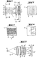
- a measuring device 1 operating in the incident light method is shown schematically in FIG.
- the radiation from a light source L is thrown onto a scanning plate 3 by a condenser 2.
- the scanning plate 3 has a division field 3 ', which consists of a group of transparent areas.
- the surrounding area 3 "of the division field 3 ' is absorbent.
- the division field 3' shows a reference mark, but can also be designed as a periodic division (incremental scale).
- Such a configuration is particularly useful if conventional (incident light or Transmitted light amplitude gratings) standards that the so-called single-field push-pull sampling is to be carried out in order to generate signals of higher quality.
- the radiation passing through the scanning plate 3 strikes a reflective incident light phase grating 4, on which it is reflected and diffracted.
- the radiation diffracted at the incident light phase grating 4 is reflected back by the scanning plate 3 and the condenser 2 and strikes a plate 5 on which photodetectors 5 ', -5'; 5 ", -5" are arranged.
- the incident light phase grating 4 has a division field 4 'which is the same as the division field 3' of the scanning plate 3.
- the division field 4 ' is designed as a phase grating with a grating constant of 10 ⁇ m.
- the surrounding area 4 ′′ of the division field 4 ′ is also designed as a phase grating, but has a grating constant of only 4 ⁇ m.
- the different grating constants of the phase grating of division field 4 'and surrounding area 4' ' lead to different diffractions, which results in different diffraction images on the plate 5 with the photodetectors 5', -5 '; 5 '', -5 ''.
- the furrows and steps of the phase grating run in the measuring direction X, which can also be seen in FIG. 3.
- the measuring direction X therefore runs perpendicular to the plane of the drawing.
- the radiation is now covered according to the coverage degree of the graduation fields 3 'and 4' of the scanning plate 3 and the phase grating 4 in the direction of the positive and negative diffraction orders - of which only the first is to be considered here - reflected and focused by the condenser 2.
- First-order diffraction patterns arise symmetrically to the light source L in the focal plane of the condenser 2.
- the plate 5 is arranged, the photodetectors 5 ', -5'; 5 ′′, -5 ′′ are placed in such a way that the first-order diffraction images of the respective phase grating 4 ′, 4 ′′ strike it exactly.
- the position of the diffraction images can be changed in a targeted manner by appropriately designing the phase grating, which will be explained in more detail later with the aid of further exemplary embodiments.
- FIG. 5 shows schematically that the invention, with a corresponding design, is also suitable for measuring devices 15 which operate using the transmitted light method.
- the radiation from a light source L5 is directed by a condenser 25 onto a scanning plate 35 which has a division field 35 '.
- a phase grating 45 is superimposed on a further division field 45 '.
- the diffraction images of the light source L5 are focused in one plane by means of imaging optics 25' in which photodetectors 55 ', - 55'; 55 '', -55 '' are arranged on a plate 55.
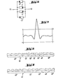
- the photodetectors 5 ', -5' and 5 '', -5 are connected together in pairs and antiparallel to each other, so that the circuit diagram according to FIG. 6 is obtained.
- the electrical signals generated by the photodetectors are evaluated by tapping at points R1 and R2 , as shown in Figure 6.
- FIG. 6 A typical signal curve of a reference mark push-pull signal according to the invention is shown in FIG. This signal present at points R1 and R2 of the circuit according to FIG. 6 can be reliably evaluated since there is a sufficient useful-interference signal ratio, because when the distance and contamination change, the signal changes essentially symmetrically to the zero line (amplitude).
- phase grating 4 'and 4'' According to FIG. 3 it can be seen that the associated diffraction images meet their associated photodetectors + 5' and + 5 '' at different locations.
- the respective photodetector + 5' or + 5 '' delivering a signal can thus be used to clearly determine which phase grating 4 'or 4''for the respective photodetector + 5 or + 5 '' diffraction pattern.
- phase grating shown in FIG. 3 is that of the rectangular profile phase grating with a different grating constant for the division field 4 'and the surroundings 4 ", but with the same (parallel) orientation.
- FIG. 8 shows in cross section a variant with an Echelette phase grating, in which the division field 48 'and the surrounding area 48' 'have different grating constants and / or alignment.
- the diffraction patterns of the illumination are deflected according to the variation, and the photodetectors assigned to the individual diffraction patterns are placed accordingly.
- the individual reference marks can be coded and differentiated by tapping the corresponding photodetectors.
- phase gratings in accordance with the operating conditions.
- the mutual alignment of the phase gratings is of particular importance, since the coding of the individual reference marks is particularly simple due to different alignment of the phase gratings and corresponding placement of the associated photodetectors.
Priority Applications (1)
| Application Number | Priority Date | Filing Date | Title |
|---|---|---|---|
| AT85102988T ATE64006T1 (de) | 1984-05-08 | 1985-03-15 | Photoelektrische messeinrichtung. |
Applications Claiming Priority (2)
| Application Number | Priority Date | Filing Date | Title |
|---|---|---|---|
| DE3416864A DE3416864C2 (de) | 1984-05-08 | 1984-05-08 | Photoelektrische Meßeinrichtung |
| DE3416864 | 1984-05-08 |
Publications (3)
| Publication Number | Publication Date |
|---|---|
| EP0160811A2 true EP0160811A2 (fr) | 1985-11-13 |
| EP0160811A3 EP0160811A3 (en) | 1987-09-16 |
| EP0160811B1 EP0160811B1 (fr) | 1991-05-29 |
Family
ID=6235167
Family Applications (1)
| Application Number | Title | Priority Date | Filing Date |
|---|---|---|---|
| EP85102988A Expired - Lifetime EP0160811B1 (fr) | 1984-05-08 | 1985-03-15 | Dispositif de mesure photo-électrique |
Country Status (5)
| Country | Link |
|---|---|
| US (1) | US4677293A (fr) |
| EP (1) | EP0160811B1 (fr) |
| JP (1) | JPS60243514A (fr) |
| AT (1) | ATE64006T1 (fr) |
| DE (2) | DE3416864C2 (fr) |
Cited By (8)
| Publication number | Priority date | Publication date | Assignee | Title |
|---|---|---|---|---|
| DE3700777A1 (de) * | 1986-01-14 | 1987-07-16 | Canon Kk | Vorrichtung zur ermittlung einer bezugsposition und mit dieser vorrichtung ausgestatteter verschluessler |
| EP0341882A2 (fr) * | 1988-05-11 | 1989-11-15 | Simmonds Precision Products Inc. | Capteurs optiques |
| US4974962A (en) * | 1986-07-03 | 1990-12-04 | Renishaw Plc | Opto-electronic scale-reading apparatus |
| EP0434973A2 (fr) * | 1989-11-30 | 1991-07-03 | Dr. Johannes Heidenhain GmbH | Dispositif opto-électronique pour la mesure de positions |
| EP0498904A1 (fr) * | 1991-02-11 | 1992-08-19 | Dr. Johannes Heidenhain GmbH | Dispositif photoélectrique de mesure de position |
| EP0669518A2 (fr) * | 1994-02-23 | 1995-08-30 | Dr. Johannes Heidenhain GmbH | Dispositif pour générer des signaux dépendants de la position |
| WO2003006926A1 (fr) * | 2001-07-09 | 2003-01-23 | Dr. Johannes Heidenhain Gmbh | Dispositif de mesure de position |
| WO2007048611A1 (fr) * | 2005-10-28 | 2007-05-03 | Hahn-Schickard-Gesellschaft für angewandte Forschung e.V. | Élément de codage pour transmetteur de position |
Families Citing this family (23)
| Publication number | Priority date | Publication date | Assignee | Title |
|---|---|---|---|---|
| DE3541199C1 (de) * | 1985-11-21 | 1987-06-25 | Heidenhain Gmbh Dr Johannes | Lichtelektrische Positionsmesseinrichtung |
| GB8615197D0 (en) * | 1986-06-21 | 1986-07-23 | Renishaw Plc | Opto-electronic scale reading apparatus |
| DE3632084A1 (de) * | 1986-09-20 | 1988-04-07 | Telefunken Electronic Gmbh | Optischer encoder |
| JPH0212017A (ja) * | 1988-06-30 | 1990-01-17 | Okuma Mach Works Ltd | 平均化回折モアレ位置検出器 |
| US4985624A (en) * | 1988-05-11 | 1991-01-15 | Simmonds Precision Products, Inc. | Optical grating sensor and method of monitoring with a multi-period grating |
| DE3834676A1 (de) * | 1988-10-12 | 1990-04-19 | Heidenhain Gmbh Dr Johannes | Photoelektrische positionsmesseinrichtung |
| US5012090A (en) * | 1989-02-09 | 1991-04-30 | Simmonds Precision Products, Inc. | Optical grating sensor and method of monitoring having a multi-period grating |
| ATE108274T1 (de) * | 1991-05-18 | 1994-07-15 | Heidenhain Gmbh Dr Johannes | Interferentielle positionsmessvorrichtung. |
| DE4212281A1 (de) * | 1991-07-11 | 1993-10-14 | Heidenhain Gmbh Dr Johannes | Interferentielle Positionsmeßvorrichtung |
| US5519492A (en) * | 1992-06-27 | 1996-05-21 | Dr. Johannes Heidenhain Gmbh | Optical arrangement for detecting the intensity modulation of partial ray beams |
| EP0579846B1 (fr) * | 1992-07-18 | 1995-08-23 | Dr. Johannes Heidenhain GmbH | Dispositif optique |
| DE19511068A1 (de) | 1995-03-25 | 1996-09-26 | Heidenhain Gmbh Dr Johannes | Lichtelektrische Positionsmeßeinrichtung |
| DE19521295C2 (de) * | 1995-06-10 | 2000-07-13 | Heidenhain Gmbh Dr Johannes | Lichtelektrische Positionsmeßeinrichtung |
| DE19525874A1 (de) * | 1995-07-15 | 1997-01-16 | Heidenhain Gmbh Dr Johannes | Positionsmeßvorrichtung |
| DE19937023A1 (de) | 1999-08-05 | 2001-02-08 | Heidenhain Gmbh Dr Johannes | Reflexions-Maßverkörperung und Verfahren zur Herstellung einer Reflexions-Maßverkörperung |
| US7002137B2 (en) * | 2001-08-30 | 2006-02-21 | Gsi Lumonics Corporation | Reference point talbot encoder |
| WO2003069278A1 (fr) * | 2002-02-14 | 2003-08-21 | Forskningscenter Risø | Capteur de deplacement optique |
| EP1872098B1 (fr) * | 2005-04-19 | 2014-06-04 | Multivac Sepp Haggenmüller GmbH & Co. KG | Machine d'emballage |
| GB0509727D0 (en) * | 2005-05-13 | 2005-06-22 | Renishaw Plc | Method and apparatus for scale manufacture |
| DE102007035345A1 (de) * | 2006-11-20 | 2008-05-21 | Dr. Johannes Heidenhain Gmbh | Positionsmesseinrichtung |
| US8537377B2 (en) | 2011-04-27 | 2013-09-17 | Raytheon Company | Absolute position encoder |
| CN103697817A (zh) * | 2012-09-27 | 2014-04-02 | 中国航空工业第六一八研究所 | 一种基于复合光栅的新型光位移传感器及其位移补偿方法 |
| DE102017201257A1 (de) * | 2017-01-26 | 2018-07-26 | Dr. Johannes Heidenhain Gmbh | Positionsmesseinrichtung |
Citations (6)
| Publication number | Priority date | Publication date | Assignee | Title |
|---|---|---|---|---|
| GB971504A (en) * | 1960-02-05 | 1964-09-30 | Emi Ltd | Improvements relating to displacement measuring apparatus employing diffraction gratings |
| US3482107A (en) * | 1966-07-26 | 1969-12-02 | Leitz Ernst Gmbh | Photoelectric position sensing device comprising light diffracting phase gratings using polarizer beam splitters for sensing the time phase position of the gratings |
| DE1814785A1 (de) * | 1968-12-14 | 1970-06-25 | Johannes Heidenhain Feinmechan | Zaehlanordnung |
| US3812352A (en) * | 1972-08-28 | 1974-05-21 | Itek Corp | Encoder readout system |
| DE2316248A1 (de) * | 1973-03-31 | 1974-10-10 | Leitz Ernst Gmbh | Fotoelektrischer schrittgeber |
| DE2405341A1 (de) * | 1974-02-05 | 1975-08-07 | Leitz Ernst Gmbh | Anordnung zur lichtmodulation |
Family Cites Families (9)
| Publication number | Priority date | Publication date | Assignee | Title |
|---|---|---|---|---|
| DE2207132A1 (de) * | 1972-02-16 | 1973-08-30 | Heidenhain Gmbh Dr Johannes | Anordnung zum messen der relativlage zweier zueinander beweglicher teile |
| JPS4926553U (fr) * | 1972-06-05 | 1974-03-07 | ||
| JPS5174659A (fr) * | 1974-12-24 | 1976-06-28 | Nippon Electric Co | |
| US4078173A (en) * | 1976-06-24 | 1978-03-07 | Pertec Computer Corporation | Light amplitude control system for position and motion transducers |
| JPS5417927A (en) * | 1977-07-09 | 1979-02-09 | Niigata Engineering Co Ltd | Regenerating method of asphalt concrete |
| US4332473A (en) * | 1979-01-31 | 1982-06-01 | Tokyo Shibaura Denki Kabushiki Kaisha | Apparatus for detecting a mutual positional relationship of two sample members |
| DE3007311C2 (de) * | 1980-02-27 | 1985-11-28 | Dr. Johannes Heidenhain Gmbh, 8225 Traunreut | Digitales lichtelektrisches Längen- oder Winkelmeßsystem |
| JPS6113784Y2 (fr) * | 1980-07-07 | 1986-04-28 | ||
| DE3229846C2 (de) * | 1982-08-11 | 1984-05-24 | Dr. Johannes Heidenhain Gmbh, 8225 Traunreut | Längen- oder Winkelmeßeinrichtung |
-
1984
- 1984-05-08 DE DE3416864A patent/DE3416864C2/de not_active Expired
-
1985
- 1985-03-15 DE DE8585102988T patent/DE3582950D1/de not_active Expired - Fee Related
- 1985-03-15 EP EP85102988A patent/EP0160811B1/fr not_active Expired - Lifetime
- 1985-03-15 AT AT85102988T patent/ATE64006T1/de not_active IP Right Cessation
- 1985-04-29 US US06/728,182 patent/US4677293A/en not_active Expired - Lifetime
- 1985-05-07 JP JP60095695A patent/JPS60243514A/ja active Granted
Patent Citations (6)
| Publication number | Priority date | Publication date | Assignee | Title |
|---|---|---|---|---|
| GB971504A (en) * | 1960-02-05 | 1964-09-30 | Emi Ltd | Improvements relating to displacement measuring apparatus employing diffraction gratings |
| US3482107A (en) * | 1966-07-26 | 1969-12-02 | Leitz Ernst Gmbh | Photoelectric position sensing device comprising light diffracting phase gratings using polarizer beam splitters for sensing the time phase position of the gratings |
| DE1814785A1 (de) * | 1968-12-14 | 1970-06-25 | Johannes Heidenhain Feinmechan | Zaehlanordnung |
| US3812352A (en) * | 1972-08-28 | 1974-05-21 | Itek Corp | Encoder readout system |
| DE2316248A1 (de) * | 1973-03-31 | 1974-10-10 | Leitz Ernst Gmbh | Fotoelektrischer schrittgeber |
| DE2405341A1 (de) * | 1974-02-05 | 1975-08-07 | Leitz Ernst Gmbh | Anordnung zur lichtmodulation |
Cited By (12)
| Publication number | Priority date | Publication date | Assignee | Title |
|---|---|---|---|---|
| DE3700777A1 (de) * | 1986-01-14 | 1987-07-16 | Canon Kk | Vorrichtung zur ermittlung einer bezugsposition und mit dieser vorrichtung ausgestatteter verschluessler |
| US4974962A (en) * | 1986-07-03 | 1990-12-04 | Renishaw Plc | Opto-electronic scale-reading apparatus |
| EP0341882A2 (fr) * | 1988-05-11 | 1989-11-15 | Simmonds Precision Products Inc. | Capteurs optiques |
| EP0341882A3 (fr) * | 1988-05-11 | 1990-04-11 | Simmonds Precision Products Inc. | Capteurs optiques |
| EP0434973A2 (fr) * | 1989-11-30 | 1991-07-03 | Dr. Johannes Heidenhain GmbH | Dispositif opto-électronique pour la mesure de positions |
| EP0434973A3 (en) * | 1989-11-30 | 1991-10-23 | Dr. Johannes Heidenhain Gmbh | Opto-electronic position measuring device |
| EP0498904A1 (fr) * | 1991-02-11 | 1992-08-19 | Dr. Johannes Heidenhain GmbH | Dispositif photoélectrique de mesure de position |
| EP0669518A2 (fr) * | 1994-02-23 | 1995-08-30 | Dr. Johannes Heidenhain GmbH | Dispositif pour générer des signaux dépendants de la position |
| EP0669518A3 (fr) * | 1994-02-23 | 1996-12-27 | Heidenhain Gmbh Dr Johannes | Dispositif pour générer des signaux dépendants de la position. |
| WO2003006926A1 (fr) * | 2001-07-09 | 2003-01-23 | Dr. Johannes Heidenhain Gmbh | Dispositif de mesure de position |
| US7057161B2 (en) | 2001-07-09 | 2006-06-06 | Dr. Johannes Heidenhain Gmbh | Position measuring device |
| WO2007048611A1 (fr) * | 2005-10-28 | 2007-05-03 | Hahn-Schickard-Gesellschaft für angewandte Forschung e.V. | Élément de codage pour transmetteur de position |
Also Published As
| Publication number | Publication date |
|---|---|
| EP0160811A3 (en) | 1987-09-16 |
| ATE64006T1 (de) | 1991-06-15 |
| US4677293A (en) | 1987-06-30 |
| DE3582950D1 (de) | 1991-07-04 |
| DE3416864A1 (de) | 1985-11-21 |
| DE3416864C2 (de) | 1986-04-10 |
| JPH0132450B2 (fr) | 1989-06-30 |
| EP0160811B1 (fr) | 1991-05-29 |
| JPS60243514A (ja) | 1985-12-03 |
Similar Documents
| Publication | Publication Date | Title |
|---|---|---|
| EP0160811B1 (fr) | Dispositif de mesure photo-électrique | |
| DE19833439B4 (de) | Optische Positionsmeßeinrichtung | |
| EP0163824B1 (fr) | Dispositif de mesure photo-électrique | |
| DE3844704C2 (fr) | ||
| DE3901869C2 (de) | Optischer Codierer | |
| EP1111345B1 (fr) | Dispositif de mesure de position avec une piste incrementielle avec deux graduations de période differente | |
| EP0137099B1 (fr) | Appareil de mesure | |
| EP0509979A2 (fr) | Dispositif de mesure de positions photo-électronique | |
| EP0083689B1 (fr) | Dispositif photo-électrique incrémentiel pour mesurer des longueurs ou des angles | |
| DE10132521A1 (de) | Positionsmesseinrichtung | |
| DE3834676C2 (fr) | ||
| DE60033075T2 (de) | Kodierer | |
| EP1524503B1 (fr) | Codeur optique | |
| DE1905392A1 (de) | Vorrichtung zum Erzeugen von elektrischen Signalen mittels eines Skalengitters,das relativ zu einem Indexgitter bewegbar ist | |
| EP0747674A2 (fr) | Dispositif photo-électrique de mesure de positions | |
| EP0222136A2 (fr) | Indicateur d'impulsion zéro à une position prédéterminée d'un porteur de codes | |
| EP1050742A2 (fr) | Unité de balayage pour un dispositif optique de mesure de la position | |
| EP0635701B1 (fr) | Dispositif de mesure de longeurs ou d'angles | |
| EP0767359B1 (fr) | Dispositif photo-électrique pour mesurer une longueur ou un angle | |
| EP0498904B1 (fr) | Dispositif photoélectrique de mesure de position | |
| DE10346380B4 (de) | Positionsmesseinrichtung | |
| EP3936830B1 (fr) | Dispositif optique de mesure de la position | |
| DE3939504C2 (fr) | ||
| DE19936181A1 (de) | Optische Positionsmeßeinrichtung | |
| DE102010002902A1 (de) | Abtasteinheit für eine optische Positionsmesseinrichtung |
Legal Events
| Date | Code | Title | Description |
|---|---|---|---|
| PUAI | Public reference made under article 153(3) epc to a published international application that has entered the european phase |
Free format text: ORIGINAL CODE: 0009012 |
|
| 17P | Request for examination filed |
Effective date: 19850323 |
|
| AK | Designated contracting states |
Designated state(s): AT CH DE FR GB IT LI NL SE |
|
| PUAL | Search report despatched |
Free format text: ORIGINAL CODE: 0009013 |
|
| AK | Designated contracting states |
Kind code of ref document: A3 Designated state(s): AT CH DE FR GB IT LI NL SE |
|
| 17Q | First examination report despatched |
Effective date: 19881118 |
|
| RAP3 | Party data changed (applicant data changed or rights of an application transferred) |
Owner name: DR. JOHANNES HEIDENHAIN GMBH |
|
| ITF | It: translation for a ep patent filed |
Owner name: DE DOMINICIS & MAYER S.R.L. |
|
| GRAA | (expected) grant |
Free format text: ORIGINAL CODE: 0009210 |
|
| AK | Designated contracting states |
Kind code of ref document: B1 Designated state(s): AT CH DE FR GB IT LI NL SE |
|
| REF | Corresponds to: |
Ref document number: 64006 Country of ref document: AT Date of ref document: 19910615 Kind code of ref document: T |
|
| ET | Fr: translation filed | ||
| GBT | Gb: translation of ep patent filed (gb section 77(6)(a)/1977) | ||
| REF | Corresponds to: |
Ref document number: 3582950 Country of ref document: DE Date of ref document: 19910704 |
|
| PG25 | Lapsed in a contracting state [announced via postgrant information from national office to epo] |
Ref country code: AT Effective date: 19920315 |
|
| PG25 | Lapsed in a contracting state [announced via postgrant information from national office to epo] |
Ref country code: SE Effective date: 19920316 |
|
| PG25 | Lapsed in a contracting state [announced via postgrant information from national office to epo] |
Ref country code: LI Effective date: 19920331 Ref country code: CH Effective date: 19920331 |
|
| PLBE | No opposition filed within time limit |
Free format text: ORIGINAL CODE: 0009261 |
|
| STAA | Information on the status of an ep patent application or granted ep patent |
Free format text: STATUS: NO OPPOSITION FILED WITHIN TIME LIMIT |
|
| 26N | No opposition filed | ||
| PG25 | Lapsed in a contracting state [announced via postgrant information from national office to epo] |
Ref country code: NL Effective date: 19921001 |
|
| NLV4 | Nl: lapsed or anulled due to non-payment of the annual fee | ||
| REG | Reference to a national code |
Ref country code: CH Ref legal event code: PL |
|
| EUG | Se: european patent has lapsed |
Ref document number: 85102988.4 Effective date: 19921005 |
|
| REG | Reference to a national code |
Ref country code: GB Ref legal event code: IF02 |
|
| PGFP | Annual fee paid to national office [announced via postgrant information from national office to epo] |
Ref country code: GB Payment date: 20020222 Year of fee payment: 18 |
|
| PGFP | Annual fee paid to national office [announced via postgrant information from national office to epo] |
Ref country code: FR Payment date: 20020315 Year of fee payment: 18 |
|
| PGFP | Annual fee paid to national office [announced via postgrant information from national office to epo] |
Ref country code: DE Payment date: 20030311 Year of fee payment: 19 |
|
| PG25 | Lapsed in a contracting state [announced via postgrant information from national office to epo] |
Ref country code: GB Free format text: LAPSE BECAUSE OF NON-PAYMENT OF DUE FEES Effective date: 20030315 |
|
| GBPC | Gb: european patent ceased through non-payment of renewal fee |
Effective date: 20030315 |
|
| PG25 | Lapsed in a contracting state [announced via postgrant information from national office to epo] |
Ref country code: FR Free format text: LAPSE BECAUSE OF NON-PAYMENT OF DUE FEES Effective date: 20031127 |
|
| REG | Reference to a national code |
Ref country code: FR Ref legal event code: ST |
|
| PG25 | Lapsed in a contracting state [announced via postgrant information from national office to epo] |
Ref country code: DE Free format text: LAPSE BECAUSE OF NON-PAYMENT OF DUE FEES Effective date: 20041001 |