EP0160793B1 - Optical tool for aligning transducer head assemblies - Google Patents
Optical tool for aligning transducer head assemblies Download PDFInfo
- Publication number
- EP0160793B1 EP0160793B1 EP85101925A EP85101925A EP0160793B1 EP 0160793 B1 EP0160793 B1 EP 0160793B1 EP 85101925 A EP85101925 A EP 85101925A EP 85101925 A EP85101925 A EP 85101925A EP 0160793 B1 EP0160793 B1 EP 0160793B1
- Authority
- EP
- European Patent Office
- Prior art keywords
- transducer
- glass
- grid
- alignment
- tool
- Prior art date
- Legal status (The legal status is an assumption and is not a legal conclusion. Google has not performed a legal analysis and makes no representation as to the accuracy of the status listed.)
- Expired - Lifetime
Links
- 230000000712 assembly Effects 0.000 title description 4
- 238000000429 assembly Methods 0.000 title description 4
- 230000003287 optical effect Effects 0.000 title description 3
- 239000011521 glass Substances 0.000 claims description 21
- 238000000926 separation method Methods 0.000 claims description 4
- 229910001220 stainless steel Inorganic materials 0.000 claims description 2
- 239000010935 stainless steel Substances 0.000 claims description 2
- 238000005530 etching Methods 0.000 claims 1
- 239000000463 material Substances 0.000 description 4
- 238000000034 method Methods 0.000 description 3
- 238000011109 contamination Methods 0.000 description 1
- 238000005260 corrosion Methods 0.000 description 1
- 230000007797 corrosion Effects 0.000 description 1
- 238000005336 cracking Methods 0.000 description 1
- 238000013500 data storage Methods 0.000 description 1
- 238000007689 inspection Methods 0.000 description 1
- 238000004519 manufacturing process Methods 0.000 description 1
- 125000006850 spacer group Chemical group 0.000 description 1
- 238000003860 storage Methods 0.000 description 1
- 230000002463 transducing effect Effects 0.000 description 1
Images


Classifications
-
- G—PHYSICS
- G11—INFORMATION STORAGE
- G11B—INFORMATION STORAGE BASED ON RELATIVE MOVEMENT BETWEEN RECORD CARRIER AND TRANSDUCER
- G11B5/00—Recording by magnetisation or demagnetisation of a record carrier; Reproducing by magnetic means; Record carriers therefor
- G11B5/48—Disposition or mounting of heads or head supports relative to record carriers ; arrangements of heads, e.g. for scanning the record carrier to increase the relative speed
- G11B5/56—Disposition or mounting of heads or head supports relative to record carriers ; arrangements of heads, e.g. for scanning the record carrier to increase the relative speed with provision for moving the head support for the purpose of adjusting the position of the head relative to the record carrier, e.g. manual adjustment for azimuth correction or track centering
-
- G—PHYSICS
- G11—INFORMATION STORAGE
- G11B—INFORMATION STORAGE BASED ON RELATIVE MOVEMENT BETWEEN RECORD CARRIER AND TRANSDUCER
- G11B33/00—Constructional parts, details or accessories not provided for in the other groups of this subclass
- G11B33/10—Indicating arrangements; Warning arrangements
Definitions
- This invention pertains to data storage disk files and more particularly to a structure and method for the precision alignment of transducer heads with respect to each other and the storage media surface.
- a magnetic disk file is initialized by servowriting the surfaces of the disks to provide permanent data relating to the tracks, sector identification and servo data for seek and track follow. These functions are performed during the build process by a servowriter that must function with a high precision of head orientation, disk angular position and disk speed.
- the servowriting device has a pair of speed heads with a precise angular separation on a common track to determine the rotational speed as a signal is sequentially sent by one head and received by the other.
- a clock head receives signals from a clock track that is precisely written to divide the disk into precision angular increments.
- four aligned servo write heads in two opposing pairs confront the disk surfaces and are used to write the permanent data consecutively track by track across all the disk surfaces.
- an head alignment tool in which the alignment of two opposing heads relative to a carriage is accomplished by the use of a single mirrored surface to reflect the image of the head core and gap into the lens of a microscope.
- the optical tool of the present invention as set out in claim 1 provides for viewing the alignment of a transducer gap with respect to an etched grid from a position radially outward of the disk location.
- the structure enables the viewing of either single transducer gaps or aligned transducer head gaps positioned at opposite surfaces of a single disk. This permits all heads on a given device to be exactingly aligned as to position and attitude with respect to one another. Since the alignment is effected using a microscope and a very small grid, problems may be encountered in locating the grid for observation. To enable the grid to be more easily located, a few lines of the grid are extended so that an observer may find and follow such extended lines to locate the grid.
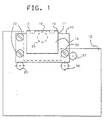
- the tool assembly 9 includes a base block 10, a spacer bar 11 and a supper plate 12.
- the support plate thickness dimension is selected to place the glass covered alignment plates 15 at the same center to center separation as adjacent disks on a drive that is simulated by the tool, while the thickness of the glass surfaced alignment plate 15 is the same as a disk used with the cooperating head assembly of such a drive.
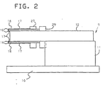
- the alignment plate 15 includes 45 degree inclined edge surfaces 16 which are polished to present a mirror finish. Overlying a portion of each major surface of alignment plate 15 is a glass sheet 17 which has a grid 19 (Fig. 4) etched on the outer surface. Alignment plate 15 is formed of half hard 302 stainless steel. This material was selected because it is not brittle if bumped, it is corrosion resistant and non-magnetic, will support the glass sheets at either side and can be polished to a good surface without chipping or cracking.
- the glass sheets 17 are secured to the alignment plate and have the grid markings etched on the outer surfaces. With the grid at the surface that interfaces with the transducer gap, no parallax occurs.
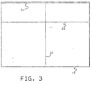
- Figs. 3 and 4 illustrate the etched grid structure.
- Line 22 represents a radial line with respect to which the transducer gap would be aligned for optimum performance.
- Line 23 intersects line 22 with the intersection overlying the circular opening 25 in alignment plate 15.
- the intersection of the etched lines 22 and 23 is used to obtain the uniform alignment of the grids 19 on the tool assembly
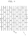
- Line 24 overlies the mirrored surfaces 16 of alignment plate 15 and the grid shown in Fig 4 is formed at the intersection of lines 22 and 24. This grid is approximately 0,3 millimeters square overall. Intersecting lines 22, 24 can be followed by an observer or operator using a bright field illuminated microscope to locate the etched grid.
- the support plate 12 has locating pins 27, 28, 29 mounted thereon to provide precise positioning of the alignment plate 15.
- the alignment plates 15 are maintained in tangential contact with the locating pins 27, 28,29 and are secured to support plate 12 by screws 30.
- the etched grid 19, as shown in Fig. 4 is a sequence of lines and the line segments with a spacing of 0,025 millimeter between centers.
- the lines are etched without filling. Lines formed by material applied to the glass surface or lines that are etched and filled with material both permit material to be rubbed off causing contamination. Further, with unfilled etched lines, the unetched portion is transparent and the etched surface portions are translucent allowing the transducer gap to be observed whether aligned with or disposed between grid lines.
- Fig. 7 shows a typical transducer head and carriage structure with four transducer heads, each having a gimbal connection to a flexure mounting from a common support assembly.
- the sliders 32 are each mounted on a flexure member 34 which includes a gimbal structure 35 at the distal end to which the slider is attached.
- a second flexure portion 36 carries a load beam 37 which abuts the slider to urge confronting transducer head assemblies toward one another and toward the surface of a magnetic disk that is positioned therebetween in the operating condition.
- the flexure mounted head assemblies are each secured to a common body 38.
- the tool assembly 9 is disposed with respect to the transducer carriage assembly under test as shown in Figs. 6 and 7.
- the alignment plates have replaced the spindle mounted disks with the transducers of the assembly positioned with the transducing gaps between sliders 32 and core pieces 33 overlying the inclined mirrored surfaces 16 and in contact with the surfaces 18 of glass sheets 17.
- the location of the transducer gaps with respect to the grid 19 can be observed by using a bright field illuminated microscope disposed to view the reflected image of the grid from mirrored surfaces 16, in the direction indicated by arrows A and B (Fig. 5).
- a bright field illuminated microscope disposed to view the reflected image of the grid from mirrored surfaces 16, in the direction indicated by arrows A and B (Fig. 5).
- the tool assembly 9 In the environment of a servowriter for writing the permanent data on rigid disk files, the tool assembly 9 is located in the servowriter in the position that would be occupied by a file to be servowritten. In place of the rotating disks mounted on a spindle in a typical file, the servowriting heads are received against the glass surfaces of the alignment plate assemblies with the transducer gaps overlying the etched grid.
- the grid presents lines or features every 0,025 millimeters (approximately each 0,001 inch).
- the grid is etched in the same surface on which the head is loaded. Since the grid and transducer gap are in the same plane, the gap may be viewed using a 50 to 100 power microscope without parallax. Gap-head location can be measured and adjusted if so desired, knowing the grid location and alignment or the gap location between servowriters compared.
Landscapes
- Supporting Of Heads In Record-Carrier Devices (AREA)
- Length Measuring Devices By Optical Means (AREA)
- Moving Of Heads (AREA)
Applications Claiming Priority (2)
| Application Number | Priority Date | Filing Date | Title |
|---|---|---|---|
| US597891 | 1984-04-09 | ||
| US06/597,891 US4630150A (en) | 1984-04-09 | 1984-04-09 | Optical tool for aligning transducer head assemblies |
Publications (2)
| Publication Number | Publication Date |
|---|---|
| EP0160793A1 EP0160793A1 (en) | 1985-11-13 |
| EP0160793B1 true EP0160793B1 (en) | 1990-05-02 |
Family
ID=24393335
Family Applications (1)
| Application Number | Title | Priority Date | Filing Date |
|---|---|---|---|
| EP85101925A Expired - Lifetime EP0160793B1 (en) | 1984-04-09 | 1985-02-22 | Optical tool for aligning transducer head assemblies |
Country Status (4)
| Country | Link |
|---|---|
| US (1) | US4630150A (cg-RX-API-DMAC7.html) |
| EP (1) | EP0160793B1 (cg-RX-API-DMAC7.html) |
| JP (1) | JPS60214478A (cg-RX-API-DMAC7.html) |
| DE (1) | DE3577489D1 (cg-RX-API-DMAC7.html) |
Families Citing this family (3)
| Publication number | Priority date | Publication date | Assignee | Title |
|---|---|---|---|---|
| AT391860B (de) * | 1988-04-25 | 1990-12-10 | Lisec Peter | Vorrichtung zum bestimmen des abstandes zwischen glastafeln von isolierglasscheiben |
| EP0427239B1 (en) * | 1989-11-07 | 1998-02-11 | Canon Kabushiki Kaisha | Recording or reproducing apparatus |
| JP2533664B2 (ja) * | 1990-01-17 | 1996-09-11 | 株式会社日立製作所 | 磁気記録装置 |
Family Cites Families (5)
| Publication number | Priority date | Publication date | Assignee | Title |
|---|---|---|---|---|
| US2247113A (en) * | 1939-12-19 | 1941-06-24 | Gen Electric | Optical alignment device |
| US3039102A (en) * | 1957-01-24 | 1962-06-12 | Lab For Electronics Inc | Alignment techniques for recording heads assembly |
| US3781489A (en) * | 1972-08-02 | 1973-12-25 | Gen Instrument Corp | Method and apparatus for aligning magnetic heads in a magnetic disc recorder |
| US3914793A (en) * | 1974-04-30 | 1975-10-21 | William W Burnham | Tape recorder alignment apparatus |
| US4537509A (en) * | 1982-03-10 | 1985-08-27 | Nortronics Company, Inc. | Optical inspection and alignment verification system |
-
1984
- 1984-04-09 US US06/597,891 patent/US4630150A/en not_active Expired - Fee Related
-
1985
- 1985-01-31 JP JP60015633A patent/JPS60214478A/ja active Granted
- 1985-02-22 DE DE8585101925T patent/DE3577489D1/de not_active Expired - Lifetime
- 1985-02-22 EP EP85101925A patent/EP0160793B1/en not_active Expired - Lifetime
Non-Patent Citations (1)
| Title |
|---|
| ABC der Optik, Hanau/Main, 1979, p. 555-556 * |
Also Published As
| Publication number | Publication date |
|---|---|
| US4630150A (en) | 1986-12-16 |
| EP0160793A1 (en) | 1985-11-13 |
| JPH043567B2 (cg-RX-API-DMAC7.html) | 1992-01-23 |
| JPS60214478A (ja) | 1985-10-26 |
| DE3577489D1 (de) | 1990-06-07 |
Similar Documents
| Publication | Publication Date | Title |
|---|---|---|
| EP0546227B1 (en) | A method of servowriting a magnetic disk drive, and a magnetic disk drive | |
| EP1204096B1 (en) | Alignment of tape head | |
| EP0209140B1 (en) | A method of measuring a minute flying height of an object and a magnetic disk apparatus | |
| EP0218811B1 (en) | Magnetic head slider assembly | |
| US4979051A (en) | Bimodal multi-track magnetic head | |
| JPH02187969A (ja) | 情報記憶媒体、並びに磁気読み取り/書き込み変換器の位置を決定する方法 | |
| US7446977B2 (en) | Recording heads having electrical pads on multiple surfaces | |
| US5091808A (en) | Two-motor servo mechanism system for a magnetic disk drive | |
| US5493463A (en) | Head alignment reference feature in a hard disk drive head-gimbal assembly | |
| US4633343A (en) | Method of and apparatus for writing data on a recording medium and the medium so produced | |
| US4537509A (en) | Optical inspection and alignment verification system | |
| US4635139A (en) | Asperity burst writer | |
| EP0160793B1 (en) | Optical tool for aligning transducer head assemblies | |
| US4470088A (en) | Pivot suspension for head arm on disk drive | |
| US5146378A (en) | Multi-track head | |
| US6256287B1 (en) | Method of manufacturing a lens system comprising two lens elements | |
| US6618217B2 (en) | System and method for determining the position of a device | |
| US6900968B2 (en) | Multi-disc servo track writer vibration isolation method and apparatus | |
| US6924958B2 (en) | Read/write transducer for hard disk drives with optical position measuring system, and manufacturing process thereof | |
| US6018512A (en) | System and method of encoding for identifying a given surface among several identically patterned disk surfaces | |
| US4562501A (en) | Transducer support apparatus | |
| US4823221A (en) | Magnetic head with planar interface position registration means | |
| US4811141A (en) | Head mounting in magnetic storage devices | |
| US4750069A (en) | Head mounting in magnetic storage devices | |
| EP0689198A2 (en) | Hard disk drive transducer-slider having controlled contact bearing with controlled pitch and roll |
Legal Events
| Date | Code | Title | Description |
|---|---|---|---|
| PUAI | Public reference made under article 153(3) epc to a published international application that has entered the european phase |
Free format text: ORIGINAL CODE: 0009012 |
|
| AK | Designated contracting states |
Designated state(s): DE FR GB |
|
| 17P | Request for examination filed |
Effective date: 19860225 |
|
| 17Q | First examination report despatched |
Effective date: 19880422 |
|
| GRAA | (expected) grant |
Free format text: ORIGINAL CODE: 0009210 |
|
| AK | Designated contracting states |
Kind code of ref document: B1 Designated state(s): DE FR GB |
|
| REF | Corresponds to: |
Ref document number: 3577489 Country of ref document: DE Date of ref document: 19900607 |
|
| ET | Fr: translation filed | ||
| PLBE | No opposition filed within time limit |
Free format text: ORIGINAL CODE: 0009261 |
|
| STAA | Information on the status of an ep patent application or granted ep patent |
Free format text: STATUS: NO OPPOSITION FILED WITHIN TIME LIMIT |
|
| 26N | No opposition filed | ||
| PGFP | Annual fee paid to national office [announced via postgrant information from national office to epo] |
Ref country code: GB Payment date: 19920113 Year of fee payment: 8 |
|
| PGFP | Annual fee paid to national office [announced via postgrant information from national office to epo] |
Ref country code: FR Payment date: 19920124 Year of fee payment: 8 |
|
| PGFP | Annual fee paid to national office [announced via postgrant information from national office to epo] |
Ref country code: DE Payment date: 19920304 Year of fee payment: 8 |
|
| PG25 | Lapsed in a contracting state [announced via postgrant information from national office to epo] |
Ref country code: GB Effective date: 19930222 |
|
| GBPC | Gb: european patent ceased through non-payment of renewal fee |
Effective date: 19930222 |
|
| PG25 | Lapsed in a contracting state [announced via postgrant information from national office to epo] |
Ref country code: FR Effective date: 19931029 |
|
| PG25 | Lapsed in a contracting state [announced via postgrant information from national office to epo] |
Ref country code: DE Effective date: 19931103 |
|
| REG | Reference to a national code |
Ref country code: FR Ref legal event code: ST |