EP0160350B1 - Magnet assembly - Google Patents
Magnet assembly Download PDFInfo
- Publication number
- EP0160350B1 EP0160350B1 EP85300180A EP85300180A EP0160350B1 EP 0160350 B1 EP0160350 B1 EP 0160350B1 EP 85300180 A EP85300180 A EP 85300180A EP 85300180 A EP85300180 A EP 85300180A EP 0160350 B1 EP0160350 B1 EP 0160350B1
- Authority
- EP
- European Patent Office
- Prior art keywords
- coils
- coil
- magnet assembly
- current
- turns
- Prior art date
- Legal status (The legal status is an assumption and is not a legal conclusion. Google has not performed a legal analysis and makes no representation as to the accuracy of the status listed.)
- Expired
Links
- 238000003384 imaging method Methods 0.000 claims description 23
- 238000000034 method Methods 0.000 claims description 12
- 230000004323 axial length Effects 0.000 claims description 3
- 238000005481 NMR spectroscopy Methods 0.000 description 21
- 239000002887 superconductor Substances 0.000 description 9
- 230000008901 benefit Effects 0.000 description 7
- 230000008859 change Effects 0.000 description 6
- 239000001307 helium Substances 0.000 description 6
- 229910052734 helium Inorganic materials 0.000 description 6
- SWQJXJOGLNCZEY-UHFFFAOYSA-N helium atom Chemical compound [He] SWQJXJOGLNCZEY-UHFFFAOYSA-N 0.000 description 6
- 238000005538 encapsulation Methods 0.000 description 5
- 239000000463 material Substances 0.000 description 5
- IJGRMHOSHXDMSA-UHFFFAOYSA-N Atomic nitrogen Chemical compound N#N IJGRMHOSHXDMSA-UHFFFAOYSA-N 0.000 description 4
- XEEYBQQBJWHFJM-UHFFFAOYSA-N Iron Chemical compound [Fe] XEEYBQQBJWHFJM-UHFFFAOYSA-N 0.000 description 4
- 239000002131 composite material Substances 0.000 description 4
- 230000000694 effects Effects 0.000 description 4
- 239000007788 liquid Substances 0.000 description 4
- 230000005855 radiation Effects 0.000 description 4
- 239000004020 conductor Substances 0.000 description 3
- 238000001816 cooling Methods 0.000 description 3
- 238000013461 design Methods 0.000 description 3
- 238000010586 diagram Methods 0.000 description 3
- 230000008569 process Effects 0.000 description 3
- 238000004804 winding Methods 0.000 description 3
- 238000000429 assembly Methods 0.000 description 2
- 230000000712 assembly Effects 0.000 description 2
- 238000010276 construction Methods 0.000 description 2
- 238000002474 experimental method Methods 0.000 description 2
- 229910052742 iron Inorganic materials 0.000 description 2
- 229910052757 nitrogen Inorganic materials 0.000 description 2
- 210000004556 brain Anatomy 0.000 description 1
- 238000004891 communication Methods 0.000 description 1
- 230000005494 condensation Effects 0.000 description 1
- 238000009833 condensation Methods 0.000 description 1
- 238000012937 correction Methods 0.000 description 1
- 230000001627 detrimental effect Effects 0.000 description 1
- 238000004519 manufacturing process Methods 0.000 description 1
- 239000011159 matrix material Substances 0.000 description 1
- 238000012545 processing Methods 0.000 description 1
- 230000009467 reduction Effects 0.000 description 1
- 230000002040 relaxant effect Effects 0.000 description 1
- 230000004044 response Effects 0.000 description 1
- 239000007787 solid Substances 0.000 description 1
Images



Classifications
-
- G—PHYSICS
- G01—MEASURING; TESTING
- G01R—MEASURING ELECTRIC VARIABLES; MEASURING MAGNETIC VARIABLES
- G01R33/00—Arrangements or instruments for measuring magnetic variables
- G01R33/20—Arrangements or instruments for measuring magnetic variables involving magnetic resonance
- G01R33/28—Details of apparatus provided for in groups G01R33/44 - G01R33/64
- G01R33/38—Systems for generation, homogenisation or stabilisation of the main or gradient magnetic field
- G01R33/3806—Open magnet assemblies for improved access to the sample, e.g. C-type or U-type magnets
-
- G—PHYSICS
- G01—MEASURING; TESTING
- G01R—MEASURING ELECTRIC VARIABLES; MEASURING MAGNETIC VARIABLES
- G01R33/00—Arrangements or instruments for measuring magnetic variables
- G01R33/20—Arrangements or instruments for measuring magnetic variables involving magnetic resonance
- G01R33/28—Details of apparatus provided for in groups G01R33/44 - G01R33/64
- G01R33/38—Systems for generation, homogenisation or stabilisation of the main or gradient magnetic field
- G01R33/381—Systems for generation, homogenisation or stabilisation of the main or gradient magnetic field using electromagnets
- G01R33/3815—Systems for generation, homogenisation or stabilisation of the main or gradient magnetic field using electromagnets with superconducting coils, e.g. power supply therefor
-
- G—PHYSICS
- G01—MEASURING; TESTING
- G01R—MEASURING ELECTRIC VARIABLES; MEASURING MAGNETIC VARIABLES
- G01R33/00—Arrangements or instruments for measuring magnetic variables
- G01R33/20—Arrangements or instruments for measuring magnetic variables involving magnetic resonance
- G01R33/28—Details of apparatus provided for in groups G01R33/44 - G01R33/64
- G01R33/38—Systems for generation, homogenisation or stabilisation of the main or gradient magnetic field
- G01R33/387—Compensation of inhomogeneities
- G01R33/3875—Compensation of inhomogeneities using correction coil assemblies, e.g. active shimming
Definitions
- the coils can be arranged so that at each position along the axis when the same error term (for example H 2 ) is summed for each coil at that position the result will be very close to zero. In this way, a resultant constant and uniform bore magnetic field is generated.
- EP-A-0144171 (Priority 11.11.83 and 11.01.84; date of publication 12.06.85) forms part of the state of the art under EPC Article 54(3) and illustrates a plurality of nested, coaxial coils for generating a substantially uniform magnetic field in a homogeneous region. However, there is no indication in this document that current flows through at least two of the coils in opposite directions.
- CH-A-437858 illustrates a shim coil arrangement in which two shim coils are positioned coaxially to modify a main magnetic field generated by an electromagnet. This leads to a bulky construction due to the need for the electromagnet and due to the low shimming strength provided by the shim coils. Furthermore, these shim coils will require a substantial diameter to length ratio.
- a magnet assembly comprises a plurality of nested, coaxial coils, and is characterised in that at least two of the coils are arranged to carry working currents in opposite directions; and in that the number of turns of the coils and their radii are such that the flow of working currents through the coils generates a substantially uniform magnetic field in a homogeneous region.
- coaxial coils of the invention should be contrasted with the previous use of shim coils. These latter coils are small relatively to the main field coils and generate relatively small correction fields unlike the coils of the invention.
- this new magnet assembly will have an axial length of approximately one quarter that of conventional imaging magnets and yet may be provided with the same bore diameter and capabilities with regard to magnet field strength and purity.
- this new magnet assembly will have an axial length of approximately one quarter that of conventional imaging magnets and yet may be provided with the same bore diameter and capabilities with regard to magnet field strength and purity.
- In the case of whole body NMR imaging only a small length of the patient needs to be obscured from view.
- One important application of the invention will be in the field of NMR head scanning and for this reason it could be incorporated into an NMR scanner dedicated to the scanning of the brain enabling such small scanners to be widely available at relatively low cost. This will also help to make NMR scanners more acceptable to the patient by reducing encapsulation of the patient.
- the radially outermost coil has the largest axial length and defines a volume within which the remaining coil or coils are positioned. This leads to a compact construction.
- At least one pair of coils are positioned symmetrically about a plane normal to the axis of the coils and passing through a mid point of the axis.
- the coil array is more simple to physically construct and is electrically more efficient that the nested coils with all coils on the mid plane.
- the electrical efficiency stems from the coils being able to be more widely separated in space which reduces the number of counter running turns necessary to balance the various error terms.
- the value of magnetic field within the coils is also reduced by this effect which also makes for more efficient use of conductor (normally superconductor).
- non-symmetric off axis coils could be used but they will require a larger number of amp turns over symmetric arrangements in order to balance odd error orders.
- the number of amp turns required from the radially outer coils is greater than from the inner coils and this may be achieved if the number of turns of the coils generally increases in the radially outward direction.
- the inner and outer radii of each coil are close to the mean radius of the coil. This is particularly advantageous where the currents in adjacent coils flow in opposite directions although this requires the use of a higher current than with conventional superconducting imaging magnets.
- the radius of a current loop is increased the strength of the nth error term due to the current loop drops in proportion to the increase in radius raised to the power n + 1.
- the coils will be made from superconductor and thus suitable cooling apparatus will be required. However, the coils could be made from non-superconducting material in some cases.
- the coils are connected in series which enables a single power source to be used for supplying the working current (which will be the same for each coil). Alternately more than one power source could be provided if the coils are not connected.
- a method of operating a magnet assembly having a plurality of nested, coaxial coils comprises supplying electrical current to the coils, and is characterised in that the flow direction of current in at least two of the coils is in opposite directions and the magnitude of the current in each coil and the number of turns of each coil and their radii is such that the flow of working currents through the coils generates a substantially uniform magnetic field in a homogeneous region.
- the magnetic field in the homogeneous region should be as uniform as possible.
- a large number of coils for example eight.
- the homogeneous region projects at least partially from the magnet assembly.
- Figure 1 illustrates diagrammatically a coil 1 having N turns and through which a current I is flowing.
- the coil has a radius a and defines the Z axis.
- Current flowing around the coil 1 generates a magnetic field (H z (b,a)) which is a vector quantity lying along the Z direction and which has a magnitude which varies in accordance with b and a.
- H z (b,a) a vector quantity lying along the Z direction and which has a magnitude which varies in accordance with b and a.
- the magnetic field can be represented by a power series for variation in two dimensions, as follows: where P is a Legendre polynomial.
- H o is the field value at the origin of single elemental circular coil.
- the remaining terms may collectively be called error terms and modify slightly the actual field at each point Z from the expected value H o .
- FIG 2 illustrates an example of a magnet assembly in accordance with the invention which comprises four coils 2-5 mounted in a conventional cryostat 6 about a common axis 7 (corresponding to the Z axis in Figure 1).
- the coils 2-5 are arranged symmetrically about a plane 8 perpendicular to the axis 7.
- Each coil 2-5 has its turns concentrated in a respective annulus.
- the coils 2-5 are formed of superconducting material and are mounted in a liquid helium vessel 9 which maintains the coils at about 4°K.
- the liquid helium vessel 9 is mounted within an inner thermal shield 10 which in turn is mounted within an outer, liquid nitrogen cooled thermal shield 11.
- a vacuum jacket 12 is provided around the outer thermal shield 11.
- a turret 13 is provided at the top of the assembly containing a heat exchangerto enable gaseous helium to cool the shield 10.
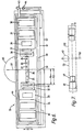
- the assembly is mounted on legs 14 ( Figure 4).
- Typical dimensions for the coils are set out in Table 1 below. Reference should be made to Figure 3 for illustration of the dimensions A i , A 2 , B.
- the radially inner ends of the cryostat 6 taper towards the axis 7 and define a bore 156 having a length of about 550 cm and a diameter of about 50 cm.
- this magnet assembly When this magnet assembly is located in an NMR imager a patient will be positioned within the bore 15 which has dimensions sufficient to receive a patient while still providing a sufficiently strong and uniform magnetic field within the bore to enable imaging to be achieved.
- the magnet assembly can then be designed with compensation up to a given order by solving the following simultaneous equations (using matrix condensation):
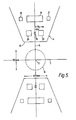
- FIG. 5 A second example of a magnet assembly is illustrated in Figure 5. This is similar in all respects to the example shown in Figure 2 except for the arrangement of coils and so details of the cryostat have been omitted for clarity. Unlike in the Figure 2 example in which all the coils 2-5 lie about the same plane of symmetry 8, the example shown in Figure 5 includes coils offset from the plane of symmetry.
- the example shown in Figure 5 comprises two nested, coaxial, coils 18, 19 positioned about the axis 7.
- two pairs of coils 20, 21 are positioned axially offset from the coils 18,19 respectively.
- the pairs of coils 20, 21 are symmetrically placed about the mid plane 8 of the magnet assembly.
- Table 3 illustrates the dimensions and number of turns for the coils 18-21 in a magnet assembly for producing a magnetic field of 1.0T in the homogeneous region 16.
- the dimensions 8 1 B 2 are illustrated for one of the coils 20 in Figure 5.
- The'-' sign against some turn densities indicate that current flow to these coils is in the opposite direction to current flow through the other coils.
- the Figure 5 example also has the advantage that the homogeneous zone 16 is easily accessible to a patient thus reducing encapsulation of the patient as in the Figure 2 example.
- Figure 6 illustrates a magnet assembly in which the homogeneous region partially projects from the bore.
- the magnet assembly illustrated in Figure 6 comprises three coaxial, nested coils 22, 23, 24 mounted on an iron former 25.
- five further nested coils 26-30 mounted in respective iron formers 31-35 are mounted coaxially with the coils 22-24.
- Each of the coils 22-24, 26-30 is positioned symmetrically about a mid plane 36 of the magnet assembly, the mid plane 36 being perpendicular to the axis 37 of the coils.
- the coils are formed from superconducting material and are mounted in a cryostat 38.
- the cryostat 38 comprises a helium can 39 within which the coils are positioned; an inner radiation shield 40; an outer radiation shield 41; and a vacuum case 42. Communication with the helium can 39 is achieved via an outlet and valve 43 while liquid nitrogen for cooling the outer radiation shield 41 is supplied via a valve and inlet connection 44.
- the magnet assembly shown in Figure 6 can be arranged so that a substantially uniform magnetic field is generated in a homogeneous region 45 which projects beyond the vacuum case 42 of the cryostat 38.
- Table 4 illustrates the form of the coils needed to achieve this.
- this configuration provides a magnetic field within the homogeneous region 45 having a peak to peak homogeneity of 100 ppm with a value of 1.0 Tesla for H o .
- a surface 46 of the cryostat 38 can be laid horizontally and the patient then laid on this surface. In this way, no encapsulation of the patient is necessary and the patient axis is now in the radial direction of the coils (not the axial direction). Other advantages of this have been mentioned earlier.
- FIG. 6 provides a flat cryostat 38 whose surface area is about half that of a standard cryostat for a solenoidal magnet. Typically, this would reduce the radiation components of the cryostat head load to about 78 mW from 155mW, thereby saving cryogen consumption. Approximately 0.1 litres of helium per hour is saved.
- FIG. 7 Another example of a magnet assembly with a projected homogeneous region is illustrated in Figure 7.
- seven coils were needed to balance all error terms up to seventh order and consequently a large number of amp turns were also required.
- a homogeneous spherical region 47 is generated with a radius of about 5 cm which should be compared with the 25 cm radius of the homogeneous region 45 of the Figure 6 example.
- the purpose of this reduction is to minimise the effect of high order error terms. For example, if H " is the field intensity expressed as due to the nth error term on 25 cm radius, then the intensity on a 5 cm radius is given by:- thus high order errors do not affect small homogeneous regions.
- the magnet assembly comprises two coils 48, 49 positioned coaxially about an axis 50 and symmetrically about a mid plane 51 of the magnet assembly.
- a cryostat 52 is indicated schematically while the formers about which the coils 48, 49 are wound have been omitted.
- a first important feature of this magnet assembly is that significant savings in amp turns for a given field have been achieved by allowing the first order error term in the magnetic field to remain uncancelled. ThTs means that a linear field variation will exist across homogeneous region 47. As mentioned previously, we consider that this will not be detrimental when the magnet assembly is used in NMR imaging apparatus.
- a second important feature of the magnet assembly is that only two coils 48, 49 are required. As a result the magnetic field value within the coils is proportionately less relative to a given bore field than for the tightly nested coils in the Figure 6 example. This assists in minimising the amount of superconductor required for a given field in the homogeneous region by virtue of the fact that critical current varies with applied field.
- a third important advantage of this arrangement arises from the small number of amp turns and consequential low field intensity within the coils 48, 49. It is possible by changing the current ratio in the coils to move the magnetic centre of the homogeneous region 47. Since the coils 48, 49 are nested concentrically about the common axis 50, the homogeneous region may be projected either further away from or closer to the flat surface 53 of the magnet assembly. Thus in NMR imaging apparatus, the patient may be moved in any direction in the plane of the magnet surface.
- the peak to peak field variation is about 10% across the homogeneous region 47.
- Figure 8 illustrates in block diagram form such apparatus which is otherwise of a conventional form.
- the apparatus comprises a magnet system 54 including one of the magnet asemblies previously described and incorporating a power supply 54' .
- the cryostat is connected to a conventional cryogenic control system 55.
- a number of gradient coils are mounted on a former around the homogeneous region generated by the magnet assembly so that different gradients of magnetic field can be set up through the homogeneous region to enable NMR imaging experiments to be carried out.
- These gradient coils are not superconducting coils and are also of a conventional form. They are driven by respective power drivers 56 controlled by control logic 57 via a waveform generator 58.
- Coils (not shown) for generating and receiving RF energy are mounted on the same former as the gradient coils, the RF transmitter being connected to an amplifier 59 which is connected to a spectrometer 60. The generation of RF pulses is controlled by the control logic 57 which is connected to the spectrometer 60.
- NMR data from the spectrometer 60 passes to a data acquisition system 61 which is controlled by the control logic 57. Data from the system 61 then passes to processing logic 62.
- the overall control of the NMR apparatus is provided by a computer 63 which is connected via a conventional RS 232 interface to an operator input station 64.
- Information for the computer 63 is stored in a disc drive 65 while the results of the imaging experiments are passed by the computer 63 to a display system 66 which can display "slices" through the patient's body on a monitor 67.
- a patient is positioned so that his body intersects part of the homogeneous region generated by the magnet assembly and this may either require positioning the patient within a bore of the magnet assembly, as in the Figure 2 example, or lying the patient on a flat surface as in the Figures 6 and 7 examples.
Landscapes
- Physics & Mathematics (AREA)
- Condensed Matter Physics & Semiconductors (AREA)
- General Physics & Mathematics (AREA)
- Electromagnetism (AREA)
- Magnetic Resonance Imaging Apparatus (AREA)
Description
- In the field of nuclear magnetic resonance (NMR) imaging it is necessary to generate a large magnitude magnetic field which is substantially uniform or homogeneous within a defined volume. In other words the rate of change of field strength in the volume is very low, or zero. In the past, this has been achieved by providing a composite solenoid comprising a number of circular coils arranged side by side on a cylinder to simulate the geometry of the solenoid. As will be explained in more detail below, the axial component (H,,) of the magnetic field generated by a coil can be expressed in the following form:

- One of the problems with this prior art composite solenoid is its comparatively large size. Typically, it may have a length of about 2.5 metres. Since the fields involved are high requiring large currents it is normally necessary to use superconducting materials which are costly and also require large amounts of cooling apparatus. Furthermore, in the case of NMR imaging a patient will be completely surrounded by the solenoid during the imaging process even where only a small part of the patient's body is to be scanned. We have realised that not only is this undesirable for the patient but it also prevents medical attendants viewing the patient during the scanning process.
- EP-A-0144171 (Priority 11.11.83 and 11.01.84; date of publication 12.06.85) forms part of the state of the art under EPC Article 54(3) and illustrates a plurality of nested, coaxial coils for generating a substantially uniform magnetic field in a homogeneous region. However, there is no indication in this document that current flows through at least two of the coils in opposite directions.
- CH-A-437858 illustrates a shim coil arrangement in which two shim coils are positioned coaxially to modify a main magnetic field generated by an electromagnet. This leads to a bulky construction due to the need for the electromagnet and due to the low shimming strength provided by the shim coils. Furthermore, these shim coils will require a substantial diameter to length ratio.
- In accordance with one aspect of the present invention, a magnet assembly comprises a plurality of nested, coaxial coils, and is characterised in that at least two of the coils are arranged to carry working currents in opposite directions; and in that the number of turns of the coils and their radii are such that the flow of working currents through the coils generates a substantially uniform magnetic field in a homogeneous region.
- We have found that cancellation of at least some of the error terms (Hi―Hn) can be obtained with a much more compact magnet assembly than has previously been manufactured. This will be explained in more detail below with reference to the drawings.
- The coaxial coils of the invention should be contrasted with the previous use of shim coils. These latter coils are small relatively to the main field coils and generate relatively small correction fields unlike the coils of the invention.
- Typically, this new magnet assembly will have an axial length of approximately one quarter that of conventional imaging magnets and yet may be provided with the same bore diameter and capabilities with regard to magnet field strength and purity. In the case of whole body NMR imaging, only a small length of the patient needs to be obscured from view. One important application of the invention will be in the field of NMR head scanning and for this reason it could be incorporated into an NMR scanner dedicated to the scanning of the brain enabling such small scanners to be widely available at relatively low cost. This will also help to make NMR scanners more acceptable to the patient by reducing encapsulation of the patient.
- Clearly, in view of the compact nature of the magnet assembly its cost will be considerably lower than that of a conventional magnet particularly since smaller amounts of superconductor will be required. Furthermore, because the volume of the magnet is much less than conventional imaging magnets the cryostat used to cool the magnet will be much more efficient thermally.
- Overall, these advantageous features should lead to a general simplification of the clinical site by virtue of employing a small, lightweight magnet assembly in the scanner.
- In some examples, the radially outermost coil has the largest axial length and defines a volume within which the remaining coil or coils are positioned. This leads to a compact construction.
- Preferably, at least one pair of coils are positioned symmetrically about a plane normal to the axis of the coils and passing through a mid point of the axis. In this case, the coil array is more simple to physically construct and is electrically more efficient that the nested coils with all coils on the mid plane. The electrical efficiency stems from the coils being able to be more widely separated in space which reduces the number of counter running turns necessary to balance the various error terms. The value of magnetic field within the coils is also reduced by this effect which also makes for more efficient use of conductor (normally superconductor). Alternatively, non-symmetric off axis coils could be used but they will require a larger number of amp turns over symmetric arrangements in order to balance odd error orders.
- In general the number of amp turns required from the radially outer coils is greater than from the inner coils and this may be achieved if the number of turns of the coils generally increases in the radially outward direction.
- Preferably, the inner and outer radii of each coil are close to the mean radius of the coil. This is particularly advantageous where the currents in adjacent coils flow in opposite directions although this requires the use of a higher current than with conventional superconducting imaging magnets. In fact, if the radius of a current loop is increased the strength of the nth error term due to the current loop drops in proportion to the increase in radius raised to the power n + 1. Thus there is a disadvantage in efficiency in attempting to balance error terms from inner coils against those from outer coils if there is a large range of coil radii.
- In all the examples discussed the coils will be made from superconductor and thus suitable cooling apparatus will be required. However, the coils could be made from non-superconducting material in some cases.
- Conveniently, the coils are connected in series which enables a single power source to be used for supplying the working current (which will be the same for each coil). Alternately more than one power source could be provided if the coils are not connected.
- In accordance with a second aspect of the present invention, a method of operating a magnet assembly having a plurality of nested, coaxial coils comprises supplying electrical current to the coils, and is characterised in that the flow direction of current in at least two of the coils is in opposite directions and the magnitude of the current in each coil and the number of turns of each coil and their radii is such that the flow of working currents through the coils generates a substantially uniform magnetic field in a homogeneous region.
- In most cases the magnetic field in the homogeneous region should be as uniform as possible. However, to achieve this requires a large number of coils (for example eight).
- We believe that complete uniformity may not be essential even when the magnet assembly forms part of NMR imaging apparatus. Relaxing this constraint by allowing the first order error term to remain uncancelled leads to a significant saving in amp turns for a given field strength. This means that a linear field variation will exist across the homogeneous region. In the process of imaging using standard magnets a linear gradient is applied to the subject in the homogeneous region in order to reference the NMR signal by frequency in space. We consider it is permissible using some imaging techniques to allow this first order gradient to exist. The gradient is pure and can be defined easily at all points in space and does not interfere with signal referencing.
- It is particularly convenient if the currents in adjacent coils are caused to flow in opposite directions.
- This latter feature leads to a further advantage of the invention. Conventional solenoid magnets have the disadvantage that as their length is reduced at constant diameter the intensity of the magnetic field around the outside of the magnet increases. In principle, a plurality of nested, coaxial coils could also give a substantial fringe field but in the case where currents in adjacent coils are caused to flow in opposite directions this fringe field is virtually eliminated altogether. This again makes the invention particularly applicable to NMR imaging.
- As previously mentioned, we have recognised that it is desirable to reduce the encapsulation of the patient and to this end, it is preferable if the homogeneous region projects at least partially from the magnet assembly.
- This is a very significant feature of the invention which is particularly applicable when the method is used in connection with magnet assemblies of an NMR imaging apparatus. In fact, if the homogeneous region projects sufficiently from the bore of the magnet assembly, a patient can lie across the end of the magnet assembly and need not be positioned within the bore of the magnet assembly at all. This leads to three important advantages:
- (i) by virtue of the patient lying across the Z (or cylindrical) axis of the coils, the component of the magnets field used for imaging is transverse to the patient axis. This permits the use of solenoidal RF transmitter and receiver coils which increases the signal to noise ratio of the NMR signal for a given field and frequency by a factor of about two.
- (ii) It is simple (because of the space available) to position the patient on the surface of the magnet assembly to achieve the centre of the homogeneous region at the centre of the region to be imaged. This permits maximum resolution of the tissue being studied in terms of image precision and avoids edge artifacts. It is not possible to achieve this degree of utilisation of the homogeneous volume within the confines of the bore of a cylindrical magnet.
- (iii) The amount of superconductor in the flat magnet per amp turn required for a given net field in the homogeneous region is less than for solenoidal coil arrangements. This is because many of the field coils are on a small diameter, since the patient does not pass within the coils. Consequently, the length of conductor per amp turn is smaller than for magnets which partially surround the patient with wire turns and must of necessity be large enough to permit patient access.
- An example of a magnet assembly and a method of generating a magnetic field using such a magnetic assembly in accordance with the invention will now be described with reference to the accompanying drawings, in which:
- Figure 1 is a schematic diagram of an electrical coil;
- Figure 2 is a side elevation partly in section of an example of the magnet assembly;
- Figure 3 illustrates the cross-section of a typical coil and the characteristic dimensions of the coil;
- Figure 4 is an end view of the assembly shown in Figure 2;
- Figure 5 is a view similar to Figure 2 but of a second example;
- Figure 6 is a view similar to Figure 2 but of a third example;
- Figure 7 is a view similar to Figure 2 but of a fourth example; and,
- Figure 8 is a block diagram of imaging apparatus.
- Figure 1 illustrates diagrammatically a coil 1 having N turns and through which a current I is flowing. The coil has a radius a and defines the Z axis. Current flowing around the coil 1 generates a magnetic field (Hz(b,a)) which is a vector quantity lying along the Z direction and which has a magnitude which varies in accordance with b and a. It can be shown that the magnetic field can be represented by a power series for variation in two dimensions, as follows:

- For simplicity, we shall consider the magnetic field along the Z axis itself where a equals 90°. In this case, the Legendre polynomial Pn is unity for all n. This leads to:


- Ho is the field value at the origin of single elemental circular coil. The remaining terms may collectively be called error terms and modify slightly the actual field at each point Z from the expected value Ho. Thus:


- It can be shown that as a given coil moves along the Z axis the sign of any particular error term changes at the original position of the coil. Thus, in the prior art solenoid, it was possible to a devise composite solenoid in which the coils were arranged so that at least the significant error terms cancelled each other out.
- Although this has been shown for 'on-axis' terms, it can also be shown that if cancellation of a given order on the Z axis is exact when comparing order strengths from two or more coils, then the effect of that order is zero at all points off the Z axis. Also if the field value of a given order on the Z axis is finite then there will be an effect of that actual order at points off the Z axis. The value of the off Z axis field will vary with the magnitude of the angle a and is given by the solid harmonic series expanded using Legendre polynomials.
- Figure 2 illustrates an example of a magnet assembly in accordance with the invention which comprises four coils 2-5 mounted in a
conventional cryostat 6 about a common axis 7 (corresponding to the Z axis in Figure 1). In this example, the coils 2-5 are arranged symmetrically about aplane 8 perpendicular to theaxis 7. Each coil 2-5 has its turns concentrated in a respective annulus. - The coils 2-5 are formed of superconducting material and are mounted in a
liquid helium vessel 9 which maintains the coils at about 4°K. Theliquid helium vessel 9 is mounted within an innerthermal shield 10 which in turn is mounted within an outer, liquid nitrogen cooledthermal shield 11. Avacuum jacket 12 is provided around the outerthermal shield 11. Aturret 13 is provided at the top of the assembly containing a heat exchangerto enable gaseous helium to cool theshield 10. The assembly is mounted on legs 14 (Figure 4). - Typical dimensions for the coils are set out in Table 1 below. Reference should be made to Figure 3 for illustration of the dimensions Ai, A2, B.

- The radially inner ends of the
cryostat 6 taper towards theaxis 7 and define a bore 156 having a length of about 550 cm and a diameter of about 50 cm. - With this configuration a bore magnetic field of 1T is achieved with a current of 959 A flowing through each coil. The `-' sign for
coils coils homogeneous region 16 of spherical shape centred on thegeometric centre 17 of the magnet assembly. - When this magnet assembly is located in an NMR imager a patient will be positioned within the
bore 15 which has dimensions sufficient to receive a patient while still providing a sufficiently strong and uniform magnetic field within the bore to enable imaging to be achieved. - It will now be described how to determine the number of turns, radii, current magnitude, and current flow direction for each coil 2-5 in order to obtain a uniform magnetic field within the
homogeneous region 16. The number of turns and current magnitude can conveniently be expressed in terms of amp turns N2, N3, N4, N5. The magnet assembly can then be designed with compensation up to a given order by solving the following simultaneous equations (using matrix condensation):
- Examination of the equations given previously will show that Hn does not change sign very frequently with radius and thus in order to achieve a sign change it is simplest to change the sign of the amp turn quantity. In other words, current is caused to flow through the coils 2-5 in alternate directions. For example, current may flow into the paper in
coils coils - We believe that it is possible to achieve error cancellation by this method at least up to and including twelfth order error terms.
- Once the amp turn quantities have been determined the actual choice of current and number of turns depends on engineering constraints. The principal factors are as follows:-
- a) Calculate a coil layout using elemental arcs and an arbitrary number of amp turns to get to the approximate bore field and necessary cancellation of error terms.
- b) Arbitrary choice of operating current needs to be made based on experience in handling current through supply leads, switches, joints and typically available capacity from superconductor designs. The current value should, in general, be as high as possible to minimise the overall coil dimensions.
- c) Given a particular operating current an exact definition of the superconductor is made using estimated values of magnetic field in the coil winding. It should be remembered that superconductors are specified in regard to performance in terms of the current value they will carry at a series of applied magnetic fields.
- d) The overall dimensions of the coils are calculated by expanding their dimensions about the original position of the elemental arcs on each coil. The overall dimension of each coil may be adjusted to achieve again the necessary cancellation of error terms. At this stage the exact value of magnetic field within all the coil windings is calculated.
- e) Calculation of the stress within the superconductor is made using the product of current field and turn radius; these calculations are refined to get the integral stress values at any point in the winding due to the local forces and the forces due to adjacent turns.
- f) Because it is unlikely that at a first iteration the calculated stresses will be acceptable, steps (c) through (e) inclusive are repeated until a safe operating stress level is achieved. Variable parameters in this iteration are current and conductor size, the other coil dimensions change in response to running current and exact number of turns. The design criteria in regard to stress are almost wholly derived from practical experience and therefore implicity relate to manufacturing techniques and design choice of materials.
- A second example of a magnet assembly is illustrated in Figure 5. This is similar in all respects to the example shown in Figure 2 except for the arrangement of coils and so details of the cryostat have been omitted for clarity. Unlike in the Figure 2 example in which all the coils 2-5 lie about the same plane of
symmetry 8, the example shown in Figure 5 includes coils offset from the plane of symmetry. - The example shown in Figure 5 comprises two nested, coaxial, coils 18, 19 positioned about the
axis 7. In addition, two pairs ofcoils coils coils mid plane 8 of the magnet assembly. - This example is more simple to construct physically since the
coils - Table 3 below illustrates the dimensions and number of turns for the coils 18-21 in a magnet assembly for producing a magnetic field of 1.0T in the
homogeneous region 16.
- The dimensions 81 B2 are illustrated for one of the
coils 20 in Figure 5. The'-' sign against some turn densities indicate that current flow to these coils is in the opposite direction to current flow through the other coils. - If a current of 1,000 A is passed through all the coils, a uniform field of 1.0T is generated within the
homogeneous zone 16, the peak to peak field error being 20 ppm. - It should be noted by comparing Tables 1 and 3 that the total number of turns required is much less in the Figure 5 example. The Figure 5 example also has the advantage that the
homogeneous zone 16 is easily accessible to a patient thus reducing encapsulation of the patient as in the Figure 2 example. - The examples described so far produce a homogeneous region which is centred on the
geometric centre 17 of the magnet assembly and is thus within the bore of the magnet assembly. Despite the short length of the bore in these cases, there is, nevertheless, some encapsulation of the patient when the magnet assembly is used in NMR imaging apparatus. - Figure 6 illustrates a magnet assembly in which the homogeneous region partially projects from the bore. The magnet assembly illustrated in Figure 6 comprises three coaxial, nested coils 22, 23, 24 mounted on an iron former 25. In addition, five further nested coils 26-30 mounted in respective iron formers 31-35 are mounted coaxially with the coils 22-24. Each of the coils 22-24, 26-30 is positioned symmetrically about a
mid plane 36 of the magnet assembly, themid plane 36 being perpendicular to theaxis 37 of the coils. - As in the previous examples, the coils are formed from superconducting material and are mounted in a
cryostat 38. Thecryostat 38 comprises a helium can 39 within which the coils are positioned; aninner radiation shield 40; anouter radiation shield 41; and avacuum case 42. Communication with the helium can 39 is achieved via an outlet andvalve 43 while liquid nitrogen for cooling theouter radiation shield 41 is supplied via a valve and inlet connection 44. - The magnet assembly shown in Figure 6 can be arranged so that a substantially uniform magnetic field is generated in a
homogeneous region 45 which projects beyond thevacuum case 42 of thecryostat 38. Table 4 illustrates the form of the coils needed to achieve this.
- With a current of 386 amps through each coil, this configuration provides a magnetic field within the
homogeneous region 45 having a peak to peak homogeneity of 100 ppm with a value of 1.0 Tesla for Ho. - It should be noted that the current direction in each alternate coil in the radial direction alternates. This is necessary since a coil must be provided for each error term to be corrected as odd order gradients do not cancel by symmetry as in a magnet assembly comprising pairs of coils distributed evenly on each side of the mid plane. This magnet assembly is, therefore, less efficient in terms of the number of amp turns for a given central field than an assembly of the long solenoid type but it has a number of important advantages.
- In particular, when the magnet assembly is used in NMR imaging apparatus, a
surface 46 of thecryostat 38 can be laid horizontally and the patient then laid on this surface. In this way, no encapsulation of the patient is necessary and the patient axis is now in the radial direction of the coils (not the axial direction). Other advantages of this have been mentioned earlier. - A further important cryogenic advantage is also achieved. The arrangement shown in Figure 6 provides a
flat cryostat 38 whose surface area is about half that of a standard cryostat for a solenoidal magnet. Typically, this would reduce the radiation components of the cryostat head load to about 78 mW from 155mW, thereby saving cryogen consumption. Approximately 0.1 litres of helium per hour is saved. - Another example of a magnet assembly with a projected homogeneous region is illustrated in Figure 7. In the previous example, seven coils were needed to balance all error terms up to seventh order and consequently a large number of amp turns were also required.
- In the example shown in Figure 7, a homogeneous
spherical region 47 is generated with a radius of about 5 cm which should be compared with the 25 cm radius of thehomogeneous region 45 of the Figure 6 example. The purpose of this reduction is to minimise the effect of high order error terms. For example, if H" is the field intensity expressed as due to the nth error term on 25 cm radius, then the intensity on a 5 cm radius is given by:-
- It will be seen in Figure 7 that the magnet assembly comprises two
coils axis 50 and symmetrically about amid plane 51 of the magnet assembly. Acryostat 52 is indicated schematically while the formers about which thecoils - A first important feature of this magnet assembly is that significant savings in amp turns for a given field have been achieved by allowing the first order error term in the magnetic field to remain uncancelled. ThTs means that a linear field variation will exist across
homogeneous region 47. As mentioned previously, we consider that this will not be detrimental when the magnet assembly is used in NMR imaging apparatus. - A second important feature of the magnet assembly is that only two
coils - A third important advantage of this arrangement arises from the small number of amp turns and consequential low field intensity within the
coils homogeneous region 47. Since thecoils common axis 50, the homogeneous region may be projected either further away from or closer to theflat surface 53 of the magnet assembly. Thus in NMR imaging apparatus, the patient may be moved in any direction in the plane of the magnet surface. - An example of a coil configuration providing a 1.OT field within the
homogeneous region 47 is set out in Table 5 below for a current of 75 amps.
- In this example, the peak to peak field variation is about 10% across the
homogeneous region 47. - One of the most important applications for the magnet assemblies just described is in NMR imaging apparatus. Figure 8 illustrates in block diagram form such apparatus which is otherwise of a conventional form. The apparatus comprises a
magnet system 54 including one of the magnet asemblies previously described and incorporating a power supply 54' . The cryostat is connected to a conventionalcryogenic control system 55. - A number of gradient coils (not shown) are mounted on a former around the homogeneous region generated by the magnet assembly so that different gradients of magnetic field can be set up through the homogeneous region to enable NMR imaging experiments to be carried out. These gradient coils are not superconducting coils and are also of a conventional form. They are driven by
respective power drivers 56 controlled bycontrol logic 57 via awaveform generator 58. Coils (not shown) for generating and receiving RF energy are mounted on the same former as the gradient coils, the RF transmitter being connected to anamplifier 59 which is connected to aspectrometer 60. The generation of RF pulses is controlled by thecontrol logic 57 which is connected to thespectrometer 60. NMR data from thespectrometer 60 passes to adata acquisition system 61 which is controlled by thecontrol logic 57. Data from thesystem 61 then passes to processinglogic 62. - The overall control of the NMR apparatus is provided by a
computer 63 which is connected via a conventional RS 232 interface to anoperator input station 64. Information for thecomputer 63 is stored in adisc drive 65 while the results of the imaging experiments are passed by thecomputer 63 to a display system 66 which can display "slices" through the patient's body on amonitor 67. - In use, a patient is positioned so that his body intersects part of the homogeneous region generated by the magnet assembly and this may either require positioning the patient within a bore of the magnet assembly, as in the Figure 2 example, or lying the patient on a flat surface as in the Figures 6 and 7 examples.
Claims (9)
Applications Claiming Priority (2)
| Application Number | Priority Date | Filing Date | Title |
|---|---|---|---|
| GB8410972 | 1984-04-30 | ||
| GB848410972A GB8410972D0 (en) | 1984-04-30 | 1984-04-30 | Magnet assembly |
Publications (2)
| Publication Number | Publication Date |
|---|---|
| EP0160350A1 EP0160350A1 (en) | 1985-11-06 |
| EP0160350B1 true EP0160350B1 (en) | 1989-03-29 |
Family
ID=10560280
Family Applications (1)
| Application Number | Title | Priority Date | Filing Date |
|---|---|---|---|
| EP85300180A Expired EP0160350B1 (en) | 1984-04-30 | 1985-01-10 | Magnet assembly |
Country Status (5)
| Country | Link |
|---|---|
| US (1) | US4701736A (en) |
| EP (1) | EP0160350B1 (en) |
| JP (1) | JP2581536B2 (en) |
| DE (1) | DE3569160D1 (en) |
| GB (1) | GB8410972D0 (en) |
Cited By (1)
| Publication number | Priority date | Publication date | Assignee | Title |
|---|---|---|---|---|
| DE4424580A1 (en) * | 1994-07-13 | 1996-01-25 | Bruker Analytische Messtechnik | Magnetic system for nuclear magnetic resonance tomograph |
Families Citing this family (57)
| Publication number | Priority date | Publication date | Assignee | Title |
|---|---|---|---|---|
| USRE36782E (en) * | 1983-11-11 | 2000-07-18 | Oxford Medical Limited | Magnet assembly for use in NMR apparatus |
| US4506247A (en) * | 1984-05-23 | 1985-03-19 | General Electric Company | Axisymmetric correction coil system for NMR magnets |
| GB8500248D0 (en) * | 1985-01-04 | 1985-02-13 | Oxford Magnet Tech | Solenoids |
| DE3616078A1 (en) * | 1986-05-13 | 1987-11-19 | Bruker Analytische Messtechnik | ELECTROMAGNETIC SYSTEM FOR THE NUCLEAR MRI |
| GB8615854D0 (en) * | 1986-06-28 | 1986-08-06 | Turner R | Magnetic field coils |
| DE3628161A1 (en) * | 1986-08-20 | 1988-02-25 | Spectrospin Ag | DEVICE FOR COMPENSATING TIME VARIANTS FIELD FAULTS IN MAGNETIC FIELDS |
| GB2207762B (en) * | 1987-06-23 | 1992-01-02 | Mitsubishi Electric Corp | Magnetic field compensating apparatus |
| JPS6458247A (en) * | 1987-08-29 | 1989-03-06 | Fuji Electric Co Ltd | Uniform magnetic field coil |
| US4812797A (en) * | 1988-03-22 | 1989-03-14 | General Electric Company | Compensation coil for temporal drift of a superconducting magnet |
| JPH01243503A (en) * | 1988-03-25 | 1989-09-28 | Toshiba Corp | Static magnetic field magnet for magnetic resonance imaging device |
| WO1990004258A1 (en) * | 1988-10-14 | 1990-04-19 | Oxford Advanced Technology Limited | Magnetic field generating assembly and method |
| GB8825529D0 (en) * | 1988-11-01 | 1988-12-07 | Oxford Magnet Tech | Magnetic field generating assembly |
| DE3907927A1 (en) * | 1989-03-11 | 1990-09-20 | Bruker Analytische Messtechnik | MAGNETIC SYSTEM |
| GB8912601D0 (en) * | 1989-06-01 | 1989-07-19 | Oxford Magnet Tech | Magnetic field generating apparatus |
| GB9002863D0 (en) * | 1990-02-08 | 1990-04-04 | Oxford Instr Ltd | Magnetic field generating assembly |
| DE4010032C2 (en) * | 1990-03-29 | 1994-03-03 | Bruker Analytische Messtechnik | Magnet system |
| US5095271A (en) * | 1990-05-14 | 1992-03-10 | General Atomics | Compact open NMR systems for in situ measurement of moisture, salinity, and hydrocarbons |
| NL9001300A (en) * | 1990-06-08 | 1992-01-02 | Koninkl Philips Electronics Nv | MAGNETIC SYSTEM FOR MAGNETIC RESONANCE. |
| JPH04240440A (en) * | 1991-01-23 | 1992-08-27 | Toshiba Corp | Magnet for mri apparatus |
| EP0535735A1 (en) * | 1991-10-03 | 1993-04-07 | Koninklijke Philips Electronics N.V. | Magnetic resonance apparatus comprising a shielded magnet |
| DE4142263C2 (en) * | 1991-12-20 | 1994-03-24 | Bruker Analytische Messtechnik | Gradient coil system |
| US5382904A (en) * | 1992-04-15 | 1995-01-17 | Houston Advanced Research Center | Structured coil electromagnets for magnetic resonance imaging and method for fabricating the same |
| US5389879A (en) * | 1992-12-18 | 1995-02-14 | Pulyer; Yuly M. | MRI device having high field strength cylindrical magnet with two axially spaced electromagnets |
| US5378988A (en) * | 1993-01-22 | 1995-01-03 | Pulyer; Yuly M. | MRI system having high field strength open access magnet |
| US5596303A (en) * | 1993-02-22 | 1997-01-21 | Akguen Ali | Superconductive magnet system with low and high temperature superconductors |
| US5428292A (en) * | 1994-04-29 | 1995-06-27 | General Electric Company | Pancake MRI magnet with modified imaging volume |
| US5396207A (en) * | 1994-08-05 | 1995-03-07 | General Electric Company | On-shoulder MRI magnet for human brain imaging |
| US5402094A (en) * | 1994-08-15 | 1995-03-28 | Enge; Harald A. | MRI mammography magnet |
| US5818319A (en) * | 1995-12-21 | 1998-10-06 | The University Of Queensland | Magnets for magnetic resonance systems |
| US5568110A (en) * | 1996-02-20 | 1996-10-22 | General Electric Company | Closed MRI magnet having reduced length |
| EP0797103B1 (en) * | 1996-03-28 | 1999-06-02 | Siemens Aktiengesellschaft | MPI magnet assembly with two separated imaging volumes |
| DE19620926C2 (en) * | 1996-05-24 | 2001-08-09 | Bruker Analytik Gmbh | Magnet arrangement for an NMR tomography system, in particular for skin and surface examinations, method for producing the magnet arrangement and gradient coil system |
| US5721523A (en) * | 1996-08-26 | 1998-02-24 | General Electric Company | Compact MRI superconducting magnet |
| US5677630A (en) * | 1996-10-21 | 1997-10-14 | General Electric Company | Planar superconducting MRI magnet |
| ATE419789T1 (en) | 1997-05-23 | 2009-01-15 | Prorhythm Inc | HIGH INTENSITY DISPOSABLE FOCUSING ULTRASONIC APPLICATOR |
| US6208143B1 (en) | 1998-04-10 | 2001-03-27 | The Board Of Trustee Of The Leland Stanford Junior University | Biplanar homogeneous field electromagnets and method for making same |
| US6255822B1 (en) | 1998-10-09 | 2001-07-03 | U.S. Philips Corporation | MRI apparatus having a short uniform field magnet with an internal space |
| US6208142B1 (en) | 1998-12-07 | 2001-03-27 | Transurgical, Inc. | Magnetic resonance apparatus and methods with shim adjustment |
| US6278351B1 (en) | 1999-01-11 | 2001-08-21 | Transurgical, Inc. | Multi-coil MRI magnet |
| AUPQ198899A0 (en) * | 1999-08-03 | 1999-08-26 | University Of Queensland, The | A method of magnet design and magnet configuration |
| EP1074852B1 (en) * | 1999-08-03 | 2006-12-13 | NMR Holdings No. 2 Pty Limited | Method for designing a superconducting magnet |
| GB0007018D0 (en) * | 2000-03-22 | 2000-05-10 | Akguen Ali | Magnetic resonance imaging apparatus and method |
| JP3847079B2 (en) * | 2000-11-21 | 2006-11-15 | ジーイー・メディカル・システムズ・グローバル・テクノロジー・カンパニー・エルエルシー | MRI equipment |
| US6700468B2 (en) * | 2000-12-01 | 2004-03-02 | Nmr Holdings No. 2 Pty Limited | Asymmetric magnets for magnetic resonance imaging |
| JP4045769B2 (en) * | 2001-10-10 | 2008-02-13 | 株式会社日立製作所 | Magnetic field generator and MRI apparatus using the same |
| DE102004043988B3 (en) * | 2004-09-11 | 2006-05-11 | Bruker Biospin Gmbh | Superconductive magnet coil arrangement |
| JP4503405B2 (en) * | 2004-09-29 | 2010-07-14 | 株式会社日立メディコ | Superconducting magnet apparatus and magnetic resonance imaging apparatus using the same |
| US7425828B2 (en) | 2005-10-11 | 2008-09-16 | Regents Of The University Of Minnesota | Frequency swept excitation for magnetic resonance |
| JP4813884B2 (en) * | 2005-12-08 | 2011-11-09 | 株式会社神戸製鋼所 | Superconducting coil |
| US7786729B2 (en) | 2006-10-31 | 2010-08-31 | Regents Of The University Of Minnesota | Method for magnetic resonance imaging |
| WO2008064231A1 (en) * | 2006-11-21 | 2008-05-29 | Steady State Imaging | Magnet for magnetic resonance imaging |
| GB0625600D0 (en) * | 2006-12-21 | 2007-01-31 | Oxford Instr Plc | Magnetic field generating system and method |
| WO2009135264A1 (en) | 2008-05-08 | 2009-11-12 | The University Of Queensland | Arrangement of coils for mri apparatus |
| IT1396080B1 (en) | 2009-10-19 | 2012-11-09 | Fond Istituto Italiano Di Tecnologia | OPEN MAGNETIC COMPLEX, PARTICULARLY FOR THE FORMATION OF IMAGES FOR MAGNETIC RESONANCE. |
| US9638776B2 (en) | 2014-08-22 | 2017-05-02 | General Electric Company | Nested coil configuration of active shims in MRI systems |
| WO2019083539A1 (en) * | 2017-10-26 | 2019-05-02 | Catalan Roberto | Electromagnetic halbach array, devices, and methods |
| CN113749639B (en) * | 2021-10-20 | 2025-02-28 | 深圳市联影高端医疗装备创新研究院 | Coil device for medical scanning system, medical scanning system and imaging method |
Citations (1)
| Publication number | Priority date | Publication date | Assignee | Title |
|---|---|---|---|---|
| EP0144171A1 (en) * | 1983-11-11 | 1985-06-12 | Oxford Advanced Technology Limited | Magnet assembly |
Family Cites Families (13)
| Publication number | Priority date | Publication date | Assignee | Title |
|---|---|---|---|---|
| US3199021A (en) * | 1960-12-19 | 1965-08-03 | Varian Associates | Apparatus for improving the homogeneity of a magnetic field |
| US3256464A (en) * | 1963-05-13 | 1966-06-14 | Nat Res Corp | Process for operating plural superconductive coils |
| US3283277A (en) * | 1963-11-21 | 1966-11-01 | Westinghouse Electric Corp | Superconducting solenoid formed from a niobium-base alloy of varying composition |
| US3406333A (en) * | 1966-04-07 | 1968-10-15 | Varian Associates | Scanned intensity magnet having field homogeneity correction coils in common with its scanning coils |
| US3394330A (en) * | 1967-01-16 | 1968-07-23 | Rca Corp | Superconductive magnet construction |
| US4038622A (en) * | 1976-04-13 | 1977-07-26 | The United States Of America As Represented By The United States Energy Research And Development Administration | Superconducting dipole electromagnet |
| FR2475281A1 (en) * | 1980-02-05 | 1981-08-07 | Radiologie Cie Gle | MAGNET WITHOUT HIGH-HOMOGENEITY MAGNETIC CIRCUIT, IN PARTICULAR FOR NUCLEAR MAGNETIC RESONANCE IMAGING |
| FR2475282B1 (en) * | 1980-02-05 | 1985-10-04 | Radiologie Cie Gle | ELECTROMAGNETIC COIL SYSTEM FOR EXAMINATION OF LARGE BODIES BY NUCLEAR MAGNETIC RESONANCE, AND HUMAN BODY IMAGING APPARATUS USING SUCH A SYSTEM |
| DE3125502A1 (en) * | 1981-06-29 | 1983-01-13 | Siemens AG, 1000 Berlin und 8000 München | Apparatus for measuring the nuclear spin resonance of specimens |
| US4456881A (en) * | 1982-01-18 | 1984-06-26 | Technicare Corporation | Gradient-coil apparatus for a magnetic resonance system |
| DE3245944A1 (en) * | 1982-12-11 | 1984-06-14 | Bruker Analytische Meßtechnik GmbH, 7512 Rheinstetten | ELECTROMAGNET FOR NMR TOMOGRAPHY |
| GB8407098D0 (en) * | 1984-03-19 | 1984-04-26 | Picker Int Ltd | Nuclear magnetic resonance apparatus |
| JPS60227403A (en) * | 1984-04-26 | 1985-11-12 | Yokogawa Hokushin Electric Corp | Coil for generating magnetic field |
-
1984
- 1984-04-30 GB GB848410972A patent/GB8410972D0/en active Pending
-
1985
- 1985-01-10 EP EP85300180A patent/EP0160350B1/en not_active Expired
- 1985-01-10 DE DE8585300180T patent/DE3569160D1/en not_active Expired
- 1985-02-01 US US06/697,322 patent/US4701736A/en not_active Expired - Lifetime
- 1985-04-30 JP JP60094569A patent/JP2581536B2/en not_active Expired - Lifetime
Patent Citations (1)
| Publication number | Priority date | Publication date | Assignee | Title |
|---|---|---|---|---|
| EP0144171A1 (en) * | 1983-11-11 | 1985-06-12 | Oxford Advanced Technology Limited | Magnet assembly |
Cited By (1)
| Publication number | Priority date | Publication date | Assignee | Title |
|---|---|---|---|---|
| DE4424580A1 (en) * | 1994-07-13 | 1996-01-25 | Bruker Analytische Messtechnik | Magnetic system for nuclear magnetic resonance tomograph |
Also Published As
| Publication number | Publication date |
|---|---|
| JPS60244006A (en) | 1985-12-03 |
| JP2581536B2 (en) | 1997-02-12 |
| US4701736A (en) | 1987-10-20 |
| GB8410972D0 (en) | 1984-06-06 |
| DE3569160D1 (en) | 1989-05-03 |
| EP0160350A1 (en) | 1985-11-06 |
Similar Documents
| Publication | Publication Date | Title |
|---|---|---|
| US4701736A (en) | Magnet assembly having a plurality of nested coaxial coils | |
| US5677630A (en) | Planar superconducting MRI magnet | |
| US5596303A (en) | Superconductive magnet system with low and high temperature superconductors | |
| EP0695949B1 (en) | MRI magnet | |
| US6411187B1 (en) | Adjustable hybrid magnetic apparatus | |
| US5194810A (en) | Superconducting MRI magnet with magnetic flux field homogeneity control | |
| US4587504A (en) | Magnet assembly for use in NMR apparatus | |
| US5436607A (en) | Open (non-enclosed) magnets for magnetic resonance imaging | |
| US5382904A (en) | Structured coil electromagnets for magnetic resonance imaging and method for fabricating the same | |
| EP2409170B1 (en) | A tesseral shim coil for a magnetic resonance system | |
| EP0138270B1 (en) | Nuclear magnetic resonance apparatus | |
| EP0468425A2 (en) | Magnet assembly | |
| EP0826977B1 (en) | Compact MRI superconducting magnet | |
| US5361054A (en) | Magnet system | |
| US4985679A (en) | Magnet assembly | |
| US4506247A (en) | Axisymmetric correction coil system for NMR magnets | |
| US4694269A (en) | Magnet system and method of its manufacture | |
| US4658229A (en) | Magnet system providing a region of substantially homogeneous field strength | |
| US5177441A (en) | Elliptical cross section gradient oil | |
| EP0757256B1 (en) | Open architecture magnetic resonance imaging superconducting magnet assembly | |
| US6965236B2 (en) | MRI system utilizing supplemental static field-shaping coils | |
| EP0770882B1 (en) | Open MRI superconductive magnet with cryogenic-fluid cooling | |
| EP0819948A1 (en) | Superconducting MR yoke magnet and method of energizing same | |
| EP0690312B1 (en) | Asymmetric gradient coils for magnetic resonance imaging | |
| US6950001B2 (en) | Superconducting open MRI magnet with transverse magnetic field |
Legal Events
| Date | Code | Title | Description |
|---|---|---|---|
| PUAI | Public reference made under article 153(3) epc to a published international application that has entered the european phase |
Free format text: ORIGINAL CODE: 0009012 |
|
| AK | Designated contracting states |
Designated state(s): DE FR GB NL |
|
| 17P | Request for examination filed |
Effective date: 19860424 |
|
| RAP1 | Party data changed (applicant data changed or rights of an application transferred) |
Owner name: OXFORD MAGNET TECHNOLOGY LIMITED |
|
| 17Q | First examination report despatched |
Effective date: 19871204 |
|
| GRAA | (expected) grant |
Free format text: ORIGINAL CODE: 0009210 |
|
| AK | Designated contracting states |
Kind code of ref document: B1 Designated state(s): DE FR GB NL |
|
| REF | Corresponds to: |
Ref document number: 3569160 Country of ref document: DE Date of ref document: 19890503 |
|
| ET | Fr: translation filed | ||
| PLBE | No opposition filed within time limit |
Free format text: ORIGINAL CODE: 0009261 |
|
| STAA | Information on the status of an ep patent application or granted ep patent |
Free format text: STATUS: NO OPPOSITION FILED WITHIN TIME LIMIT |
|
| 26N | No opposition filed | ||
| REG | Reference to a national code |
Ref country code: GB Ref legal event code: IF02 |
|
| PGFP | Annual fee paid to national office [announced via postgrant information from national office to epo] |
Ref country code: GB Payment date: 20040107 Year of fee payment: 20 |
|
| PGFP | Annual fee paid to national office [announced via postgrant information from national office to epo] |
Ref country code: FR Payment date: 20040108 Year of fee payment: 20 |
|
| PGFP | Annual fee paid to national office [announced via postgrant information from national office to epo] |
Ref country code: NL Payment date: 20040121 Year of fee payment: 20 |
|
| PGFP | Annual fee paid to national office [announced via postgrant information from national office to epo] |
Ref country code: DE Payment date: 20040122 Year of fee payment: 20 |
|
| PG25 | Lapsed in a contracting state [announced via postgrant information from national office to epo] |
Ref country code: GB Free format text: LAPSE BECAUSE OF EXPIRATION OF PROTECTION Effective date: 20050109 |
|
| PG25 | Lapsed in a contracting state [announced via postgrant information from national office to epo] |
Ref country code: NL Free format text: LAPSE BECAUSE OF EXPIRATION OF PROTECTION Effective date: 20050110 |
|
| REG | Reference to a national code |
Ref country code: GB Ref legal event code: PE20 |
|
| NLV7 | Nl: ceased due to reaching the maximum lifetime of a patent |
Effective date: 20050110 |
|
| REG | Reference to a national code |
Ref country code: FR Ref legal event code: TQ Ref country code: FR Ref legal event code: CD Ref country code: FR Ref legal event code: CA |