JP4503405B2 - Superconducting magnet apparatus and magnetic resonance imaging apparatus using the same - Google Patents
Superconducting magnet apparatus and magnetic resonance imaging apparatus using the same Download PDFInfo
- Publication number
- JP4503405B2 JP4503405B2 JP2004283837A JP2004283837A JP4503405B2 JP 4503405 B2 JP4503405 B2 JP 4503405B2 JP 2004283837 A JP2004283837 A JP 2004283837A JP 2004283837 A JP2004283837 A JP 2004283837A JP 4503405 B2 JP4503405 B2 JP 4503405B2
- Authority
- JP
- Japan
- Prior art keywords
- superconducting
- coil
- coils
- magnetic field
- container
- Prior art date
- Legal status (The legal status is an assumption and is not a legal conclusion. Google has not performed a legal analysis and makes no representation as to the accuracy of the status listed.)
- Expired - Fee Related
Links
Images


Description
本発明は、磁気共鳴イメージング(以下、「MRI」と略記する)装置用の超電導磁石装置に関し、特に小型軽量化しつつクエンチさせることなく安定して動作させる技術に関する。 The present invention relates to a superconducting magnet apparatus for a magnetic resonance imaging (hereinafter abbreviated as “MRI”) apparatus, and more particularly to a technique for stably operating without quenching while reducing the size and weight.
MRI装置用超電導磁石装置の効率を向上させる、即ち、超電導コイルの(電流×ターン数)に対する中心磁場強度を高めようとする試みは多くなされてきた。
その目的を達成する一つの方法は、超電導コイル(電流分布)をできるだけ磁場中心に近づけて配置することである。すなわち、同じ電流量であれば、磁場中心に近く配置するほど、より高い磁場を発生することが可能である。逆に、中心磁場強度が同一であれば、超電導コイルを磁場中心に近く配置するほど、電流量を下げることができる。この結果として、電磁力や経験磁場を下げることが可能となり、磁石製造コストの低減には非常に有効である。
Many attempts have been made to improve the efficiency of the superconducting magnet device for the MRI apparatus, that is, to increase the central magnetic field strength with respect to (current × number of turns) of the superconducting coil.
One way to achieve that goal is to place the superconducting coil (current distribution) as close to the center of the magnetic field as possible. That is, for the same amount of current, the closer to the magnetic field center, the higher the magnetic field can be generated. Conversely, if the central magnetic field strength is the same, the amount of current can be reduced as the superconducting coil is arranged closer to the magnetic field center. As a result, it is possible to reduce the electromagnetic force and the empirical magnetic field, which is very effective for reducing the magnet manufacturing cost.
上記課題に関して、以下の様な公知技術がある。
(特許文献1)には、熱伝達によって超電導コイルを冷却することで、超電導状態を維持する温度よりも低い温度に超電導線材を維持しているオープンアクセス磁気共鳴撮像装置(図1,8参照)が開示されている。装置10の部品(超電導コイル等)は、クライオクーラ100に接続されているケーブルやバー等の複数個の中実熱伝導体と熱伝導接触させることにより、完全な伝導により冷却されている。これにより、ヘリウムのような液体冷却剤を消費することなく、クライオクーラ100によって諸部品を必要な温度に迄低下させている。
Regarding the above problems, there are the following known techniques.
(Patent Document 1) describes an open access magnetic resonance imaging device that maintains a superconducting wire at a temperature lower than the temperature at which the superconducting state is maintained by cooling the superconducting coil by heat transfer (see FIGS. 1 and 8). Is disclosed. The components (such as superconducting coils) of the
(特許文献2)には、ヘリウム槽の外に配置することで超電導コイルを撮像空間に近づけ、磁場発生効率を高めたダブルドーナツ型オープン型超電導磁石(図1,5参照)が開示されている。実施例として、デュワー瓶352の外側に配設されていると共にデュワー瓶352と固体伝導で熱的に接触している超伝導主コイル342が設けられている。同様に、超伝導バッキング・コイル380は、デュワー瓶352の外側に配設されていると共にデュワー瓶352と固体伝導で熱的に接触している。 (Patent Document 2) discloses a double-doughnut-type open superconducting magnet (see FIGS. 1 and 5) in which the superconducting coil is placed close to the imaging space by placing it outside the helium tank and the magnetic field generation efficiency is increased. . As an example, a superconducting main coil 342 is provided that is disposed outside the Dewar 352 and is in thermal contact with the Dewar 352 by solid conduction. Similarly, superconducting backing coil 380 is disposed outside Dewar 352 and is in thermal contact with Dewar 352 in solid conduction.
超伝導主コイル342並びに超伝導バッキング・コイル380をデュワー瓶352の外側に配置し、しかもデュワー瓶352の壁からの固体伝導によりデュワー瓶352内の低温流体340によって冷却することにより、コイルは構造的に、磁石の開放空間374に縦方向に近く配置することができ、同じ強さの磁界に必要とされる超伝導主コイルの量を減少させることにより、磁石310のコストが低下する。
しかし、上記の特許文献には、以下のような課題に対する解決策が開示されていない。
(特許文献1)に開示された超電導磁石においては、ヘリウムのような冷媒を用いてないために、冷凍機によって超電導コイルを所定温度に冷却する場合、停電や故障などにより冷凍機が停止すると、コイル自体及びそれと接触している熱伝導体の熱容量が小さいために、数十分程度の短時間のうちに温度が上昇し、クエンチを発生してしまう可能性がある。
However, the above patent document does not disclose a solution to the following problem.
In the superconducting magnet disclosed in (Patent Document 1), since a refrigerant such as helium is not used, when the superconducting coil is cooled to a predetermined temperature by the refrigerator, when the refrigerator is stopped due to a power failure or failure, Since the heat capacity of the coil itself and the heat conductor in contact with the coil itself is small, the temperature may rise in a short time of several tens of minutes, which may cause quenching.
(特許文献2)に開示された超電導磁石においては、図5に示されているように、コイルの数が4個程度と少ない場合には構成可能であるが、数が増えるにつれて伝導冷却のための構造が複雑になる。また、永久電流スイッチ(PCS)や超電導接続部のように、一般の超電導線材に比較して安定性が低い部品はできるだけ、確実に冷やしておくことが必要であるが、この点は考慮されていない。
そこで、本発明は、超電導コイルの数が5個以上と比較的多い場合においても、磁場発生効率が高く、小型軽量でクエンチすることなく安定して動作するMRI装置用超電導磁石装置を提供することを目的とする。
The superconducting magnet disclosed in (Patent Document 2) can be configured when the number of coils is as small as about four as shown in FIG. The structure becomes complicated. In addition, it is necessary to cool parts that are less stable than general superconducting wires, such as permanent current switches (PCS) and superconducting connections, as much as possible, but this is taken into consideration. Absent.
Accordingly, the present invention provides a superconducting magnet device for an MRI apparatus that has a high magnetic field generation efficiency, is small and lightweight, and operates stably without quenching even when the number of superconducting coils is relatively large, such as five or more. With the goal.
上記課題を解決するために、本発明の超電導磁石装置は以下のように構成される。即ち、
所定領域に均一静磁場を発生するための複数の超電導コイルと、前記複数の超電導コイルを収納して所定温度に冷却するための収納容器と、を含む静磁場発生手段を有し、
前記収納容器は、前記複数の超電導コイルを冷却するための冷媒を内包する冷媒容器と、該冷媒容器を収納するための真空容器と、を備えてなる超電導磁石装置において、前記複数の超電導コイルの内の少なくとも一つは、前記冷媒容器と前記真空容器との間に配置された外部超電導コイルであり、該冷却容器と該外部超電導コイルとを熱的に接続する熱伝導部材が配置されていることを特徴とする。
In order to solve the above problems, the superconducting magnet device of the present invention is configured as follows. That is,
Has a static magnetic field generating means including a plurality of superconducting coils, and container for cooling to a predetermined temperature by accommodating the plurality of superconducting coils, a for generating a uniform static magnetic field in a predetermined region,
The receiving container includes a coolant tank for containing a coolant for cooling the plurality of superconducting coils, in a superconducting magnet device including a vacuum vessel, a for housing the refrigerant container, the plurality of superconducting coils at least one of the inner is an external superconducting coil disposed between the front Symbol refrigerant container and the vacuum container and the cooling container and the external superconducting coil is disposed a heat transfer member thermally connects It is characterized by being.
本発明の超電導磁石装置の好ましい一実施態様は、複数の超電導コイルは、1以上の主コイル、1以上の均一度制御用コイル、及び1以上のシールドコイルを有し、前記外部超電導コイルは、前記1以上の主コイルの内の少なくとも1つであることを特徴とする。
In a preferred embodiment of the superconducting magnet device according to the present invention, the plurality of superconducting coils include one or more main coils, one or more uniformity control coils, and one or more shield coils . It is at least one of the one or more main coils.
また、本発明の超電導磁石装置の好ましい一実施態様は、前記外部超電導コイルは、前記1以上の均一度制御用コイルの内の少なくとも一つを有し、該均一度制御用コイルは前記熱伝導部材に熱的に接続されていることを特徴とする。
In a preferred embodiment of the superconducting magnet device according to the present invention, the external superconducting coil has at least one of the one or more uniformity control coils, and the uniformity control coil is the heat conduction coil. It is characterized by being thermally connected to the member .
また、前記外部超電導コイルは、前記1以上のシールドコイルの内の少なくとも一つを有することを特徴とする。
また、上記超電導磁石を備えた磁気共鳴イメージング装置とする。
The external superconducting coil includes at least one of the one or more shield coils.
The magnetic resonance imaging apparatus includes the superconducting magnet.
以上説明したように、本発明によれば、ヘリウム槽を備えてその内部に液体ヘリウムを有しているため、冷凍機が停止した場合にも短時間でクエンチを発生することは無く、安定した動作が可能となる。また、主コイル以外の超電導コイル及びPCSや超電導接続部を体ヘリウムに浸漬することが可能なので、超電導安定性を確保することが可能となる。 As described above, according to the present invention, since a helium tank is provided and liquid helium is contained therein, even when the refrigerator is stopped, quenching does not occur in a short time, and stable. Operation is possible. In addition, since the superconducting coil other than the main coil, the PCS, and the superconducting connection portion can be immersed in the body helium, it is possible to ensure superconducting stability.
以下、添付図面に従って本発明のMRI装置の好ましい実施の形態について詳説する。なお、発明の実施形態を説明するための全図において、同一機能を有するものは同一符号を付け、その繰り返しの説明は省略する。 Hereinafter, preferred embodiments of the MRI apparatus of the present invention will be described in detail with reference to the accompanying drawings. Note that components having the same function are denoted by the same reference symbols throughout the drawings for describing the embodiments of the invention, and the repetitive description thereof is omitted.
最初に、本発明に係るMRI装置の概略を説明する。図8に本発明に係る水平磁場方式のMRI装置の一実施例の全体基本構成の斜視図を示す。ただし、本発明は水平磁場方式に限定されず、他の垂直磁場方式等にも適用することができる。このMRI装置は、核磁気共鳴(NMR)現象を利用して被検体の断層画像を得るもので、図8に示すように被検体にNMR現象を誘起してNMR信号を受信するための各種装置を収容するガントリ51、被検体を載置するテーブル52、ガントリ内各種装置を制御する電源や各種制御装置を収納した筐体53、および受信したNMR信号を処理して被検体の段増画像を再構成する処理装置54からなり、それぞれ電源・信号線55で接続される。ガントリとテーブルは図示してない高周波電磁波と静磁場を遮蔽するシールドルーム内に配置され、筐体53と処理装置54はシールドルーム外に配置される。 First, an outline of the MRI apparatus according to the present invention will be described. FIG. 8 shows a perspective view of the overall basic configuration of an embodiment of the horizontal magnetic field type MRI apparatus according to the present invention. However, the present invention is not limited to the horizontal magnetic field method, and can be applied to other vertical magnetic field methods. This MRI apparatus uses a nuclear magnetic resonance (NMR) phenomenon to obtain a tomographic image of an object. As shown in FIG. 8, various apparatuses for inducing an NMR phenomenon in an object and receiving NMR signals. A gantry 51 that houses a subject, a table 52 on which a subject is placed, a power source that controls various devices in the gantry and a housing 53 that houses various control devices, and a received NMR signal to process a step-up image of the subject. It consists of processing devices 54 to be reconfigured, and each is connected by a power source / signal line 55. The gantry and the table are arranged in a shield room that shields a high-frequency electromagnetic wave and a static magnetic field (not shown), and the casing 53 and the processing device 54 are arranged outside the shield room.
図9は本発明に係るMRI装置の一実施例に関する全体構成を示すブロック図である。このMRI装置は、核磁気共鳴(NMR)現象を利用して被検体の断層画像を得るもので、図9に示すように、MRI装置は静磁場発生系2と、傾斜磁場発生系3と、送信系5と、受信系6と、信号処理系7と、シーケンサ4と、中央処理装置(CPU)8とを備えて構成される。
FIG. 9 is a block diagram showing the overall configuration of an embodiment of the MRI apparatus according to the present invention. This MRI apparatus uses a nuclear magnetic resonance (NMR) phenomenon to obtain a tomographic image of a subject, and as shown in FIG. 9, the MRI apparatus includes a static magnetic field generation system 2, a gradient magnetic
静磁場発生系2は、垂直磁場方式であれば、被検体1の周りの空間にその体軸と直交する方向に、水平磁場方式であれば、体軸方向に均一な静磁場を発生させるもので、被検体1の周りに超電導方式の静磁場発生源が配置されている。静磁場発生系2はガントリ51内に収容される。 The static magnetic field generation system 2 generates a uniform static magnetic field in the direction perpendicular to the body axis in the space around the subject 1 if the vertical magnetic field method is used, and in the direction of the body axis if the horizontal magnetic field method is used. Thus, a superconducting static magnetic field generation source is arranged around the subject 1. The static magnetic field generation system 2 is accommodated in the gantry 51.
傾斜磁場発生系3は、MRI装置の座標系(静止座標系)であるX,Y,Zの3軸方向に巻かれた傾斜磁場コイル9と、それぞれの傾斜磁場コイルを駆動する傾斜磁場電源10とから成り、後述のシ−ケンサ4からの命令に従ってそれぞれのコイルの傾斜磁場電源10を駆動することにより、X,Y,Zの3軸方向に傾斜磁場Gx,Gy,Gzを印加する。撮影時には、スライス面(撮影断面)に直交する方向にスライス方向傾斜磁場パルス(Gs)を印加して被検体1に対するスライス面を設定し、そのスライス面に直交して且つ互いに直交する残りの2つの方向に位相エンコード方向傾斜磁場パルス(Gp)と周波数エンコード方向傾斜磁場パルス(Gf)を印加して、エコー信号にそれぞれの方向の位置情報をエンコードする。傾斜磁場コイル9はガントリ51内に、傾斜磁場電源10は筐体53にそれぞれ収容される。
The gradient magnetic
シーケンサ4は、高周波磁場パルス(以下、「RFパルス」という)と傾斜磁場パルスをある所定のパルスシーケンスで繰り返し印加する制御手段で、CPU8の制御で動作し、被検体1の断層画像のデータ収集に必要な種々の命令を送信系5、傾斜磁場発生系3、および受信系6に送る。シーケンサ4は筐体53内に収容される。
The sequencer 4 is a control means that repeatedly applies a high-frequency magnetic field pulse (hereinafter referred to as “RF pulse”) and a gradient magnetic field pulse in a predetermined pulse sequence, and operates under the control of the
送信系5は、被検体1の生体組織を構成する原子の原子核スピンに核磁気共鳴を起こさせるためにRFパルスを照射するもので、高周波発振器11と変調器12と高周波増幅器13と送信側の高周波コイル(送信コイル)14aとから成る。高周波発振器11から出力された高周波パルスをシーケンサ4からの指令によるタイミングで変調器12により振幅変調し、この振幅変調された高周波パルスを高周波増幅器13で増幅した後に被検体1に近接して配置された高周波コイル14aに供給することにより、RFパルスが被検体1に照射される。一般的に高周波コイル14aがガントリ51内に収容され、他は筐体53内に収容される。
The
受信系6は、被検体1の生体組織を構成する原子核スピンの核磁気共鳴により放出されるエコー信号(NMR信号)を検出するもので、受信側の高周波コイル(受信コイル) 14bと信号増幅器15と直交位相検波器16と、A/D変換器17とから成る。送信側の高周波コイル14aから照射された電磁波によって誘起された被検体1の応答のNMR信号が被検体1に近接して配置された高周波コイル14bで検出され、信号増幅器15で増幅された後、シーケンサ4からの指令によるタイミングで直交位相検波器16により直交する二系統の信号に分割され、それぞれがA/D変換器17でディジタル量に変換されて、信号処理系7に送られる。
一般的に受信系6を構成する前記装置群はガントリ51内に収容される。
The receiving system 6 detects an echo signal (NMR signal) emitted by nuclear magnetic resonance of nuclear spins constituting the biological tissue of the subject 1, and receives a high-frequency coil (receiving coil) 14b and a
Generally, the device group constituting the receiving system 6 is accommodated in a gantry 51.
信号処理系7は、各種データ処理と処理結果の表示及び保存等を行うもので、光ディスク19、磁気ディスク18等の外部記憶装置と、CRT等からなるディスプレイ20とを有し、受信系6からのデータがCPU8に入力されると、CPU8が信号処理、画像再構成等の処理を実行し、その結果である被検体1の断層画像をディスプレイ20に表示すると共に、外部記憶装置の磁気ディスク18等に記録する。信号処理系7は処理装置54内に収容される。
The signal processing system 7 performs various data processing and display and storage of processing results, and has an external storage device such as an
操作部25は、MRI装置の各種制御情報や上記信号処理系7で行う処理の制御情報を入力するもので、トラックボール又はマウス23、及び、キーボード24から成る。この操作部25はディスプレイ20に近接して配置され、操作者がディスプレイ20を見ながら操作部25を通してインタラクティブにMRI装置の各種処理を制御する。
The
なお、図9において、送信側の高周波コイル14aと傾斜磁場コイル9は、被検体1が挿入される静磁場発生系2の静磁場空間内に、垂直磁場方式であれば被検体1に対向して、水平磁場方式であれば被検体1を取り囲むようにして設置されている。また、受信側の高周波コイル14bは、被検体1に対向して、或いは取り囲むように設置されている。
In FIG. 9, the high-
現在MRI装置の撮像対象核種は、臨床で普及しているものとしては、被検体の主たる構成物質である水素原子核(プロトン)である。プロトン密度の空間分布や、励起状態の緩和時間の空間分布に関する情報を画像化することで、人体頭部、腹部、四肢等の形態または、機能を2次元もしくは3次元的に撮像する。 Currently, the radionuclide to be imaged by the MRI apparatus is a hydrogen nucleus (proton) which is a main constituent material of the subject as widely used in clinical practice. By imaging information on the spatial distribution of proton density and the spatial distribution of relaxation time in the excited state, the form or function of the human head, abdomen, limbs, etc. is imaged two-dimensionally or three-dimensionally.
以下、上記MRI装置の静磁場発生源として超電導コイルを用いた超電導磁石装置における本発明を説明する。
(第1の実施例)
最初に、本発明の第1の実施例を図1に基づいて説明する。図1は、水平型超電導磁石の断面図を示す。図1は1/4領域を示しており、水平方向の中心軸の周りに複数の同心円状の超電導コイルが配置され、磁石の中央部に高い均一度を持った静磁場を発生させる。静磁場は水平方向の向きを持っている。磁石は、真空容器101、熱シールド板102、ヘリウム槽103、冷凍機(図示せず)を構成要素として含む。これらは、従来装置の構成と同様である。
Hereinafter, the present invention in a superconducting magnet apparatus using a superconducting coil as a static magnetic field generation source of the MRI apparatus will be described.
(First embodiment)
First, a first embodiment of the present invention will be described with reference to FIG. FIG. 1 shows a cross-sectional view of a horizontal superconducting magnet. FIG. 1 shows a quarter region, in which a plurality of concentric superconducting coils are arranged around a central axis in the horizontal direction, and a static magnetic field with high uniformity is generated at the center of the magnet. The static magnetic field has a horizontal orientation. The magnet includes a
本発明においては、静磁場を発生するための超電導コイルは、ヘリウム槽103の内部と外部とに分離して配置される。コイルは大別して、ガントリ中心部に静磁場を発生するための主コイル104、この静磁場の均一度を高めるための均一度制御用コイル105,106,107,ガントリ外部の漏洩磁場を抑制するためのシールドコイル108の3種類から構成される。図1に示すように、本実施例では主コイル104をヘリウム槽103の外部であって、且つ、熱シールド板102の内側に配置している。こうすることで、主コイル104から磁場中心までの距離を近づけることができ、磁場の発生効率を高めることが可能である。あるいは、従来構成と同様の磁場発生効率とした場合には、オープン性をより高めたガントリ(磁石)とすることが可能となる。
In the present invention, the superconducting coil for generating a static magnetic field is arranged separately in the
これを説明するために、図2に示す従来構造と図3に示す本発明の構造とを比較する。両図は、説明のために主コイル104近傍のみを拡大したものであり、その他は図1と同様である。図2と図3とで、磁場中心からコイルまでの距離は同一としている。従って、磁場発生効率は同じとなっている。図3から分かるように、本実施例では熱シールド板102と主コイル104との間にヘリウム槽103が入らないために、ヘリウム槽103の内周直径は均一度制御用コイル部(105〜107)の内周径で規定される。
In order to explain this, the conventional structure shown in FIG. 2 is compared with the structure of the present invention shown in FIG. In both figures, only the vicinity of the
即ち、本発明においては、磁場発生効率に対する寄与が大きい主コイル104のみをヘリウム槽103の外部に配置し、他のコイルはヘリウム槽103内部に配置することで、従来課題を解決している。
均一度制御用コイルは、主コイル104に比べて要求される起磁力(電流量)は一般に小さいため、磁場中心からの距離が若干遠くなっても、その影響は主コイルに比較すると小さい。
この結果として、熱シールド板102、及び真空容器101の内周直径も大きくすることが出来る。即ち、中心軸から真空容器101までの距離(d)を図2の従来例に比べて大きくすることが出来る。この結果として、広い開口を実現できるので、オープン性の高い装置を提供できる。
That is, in the present invention, only the
The uniformity control coil generally requires a smaller magnetomotive force (current amount) than the
As a result, the inner diameters of the
一方、本実施例においては、全体のコイル数を10個としており、(特許文献2)の4個に比べて多くなっている。また、軸長も長いために、これらのコイル全てを伝導で冷却するためには、
(a)伝導部材の熱抵抗を大幅に下げる。
(b)能力の高い冷凍機を使用する。
(c)冷凍機の数を増やす。
などの対応が必要となる。しかし、(a)では熱伝導率の高い材料を使用するとか、伝導部材の断面積を増すとかする必要がある。これらは、高価な材料が必要であったり、重量が増加したりするなどのデメリットが大きい。又、(b)(c)の場合には、磁石装置のコストが増加するデメリットがある。更に、(c)の場合には、冷凍機の使用電力量が増加するために、ランニングコストの増加にも繋がる。
On the other hand, in the present embodiment, the total number of coils is 10, which is larger than the four coils in (Patent Document 2). Also, because the shaft length is long, in order to cool all these coils by conduction,
(A) The thermal resistance of the conductive member is greatly reduced.
(B) Use a refrigerator with high capacity.
(C) Increase the number of refrigerators.
It is necessary to take measures such as However, in (a), it is necessary to use a material having high thermal conductivity or to increase the cross-sectional area of the conductive member. These have great demerits such as requiring expensive materials and increasing the weight. In the cases (b) and (c), there is a demerit that the cost of the magnet device increases. Furthermore, in the case of (c), the amount of electric power used by the refrigerator increases, leading to an increase in running cost.
本発明においては、ヘリウム槽103を有しているため、冷凍機が停止した場合においても、入熱は液体ヘリウムの気化熱により消費されるため、コイルの温度上昇は緩やかになる。従って、(特許文献1)のように、冷凍機が停止した場合にも短時間でクエンチを発生することは無く、安定した動作が可能となる。
In the present invention, since the
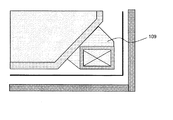
主コイル104は高熱伝導率材109によりヘリウム槽103と熱的に接続されていることにより、超電導性能を発現する温度以下に冷却されている。この温度は必ずしもヘリウムの沸点温度である必要はなく、使用する超電導コイルの線材特性に応じた設計を行えばよい。いわゆる、高温超電導材料109を線材に使用することで、温度制限を緩和することが可能となる。
Since the
高熱伝導率材109としては、高純度のアルミニウムや銅等を使用することができる。また、ヘリウムの配管を別途、高熱伝導率材109に埋め込む、或いは接触させるなどすることで、更に積極的にコイルを冷却することも可能である。或いは、ヘリウム槽103と高熱伝導率材109との間に柔軟性が高く、熱伝導率の高い材料(例えば、インジウム等)を挟み込むことで、機械的な接触性を高めることで、熱伝達率を向上させることも可能である。更に、冷凍機によって高熱伝導率材109を冷却することも可能である。
As the high
また、ヘリウム槽103内に置かれたコイルは液体ヘリウムにより均一に冷却することが可能であり、伝導冷却のために複雑な機構を設ける必要はない。
更に、図には示さないが、PCSや超電導接続部を液体ヘリウムに浸漬することが可能なので、温度を一定に維持することができ、超電導安定性を確保することが可能となる。
Further, the coil placed in the
Furthermore, although not shown in the figure, the PCS and the superconducting connection can be immersed in liquid helium, so that the temperature can be kept constant and the superconducting stability can be ensured.
以上説明したように、本実施例によれば、ヘリウム槽を備えてその内部に液体ヘリウムを有しているため、冷凍機が停止した場合にも短時間でクエンチを発生することは無く、安定した動作が可能となる。また、主コイル以外の超電導コイル及びPCSや超電導接続部を体ヘリウムに浸漬することが可能なので、超電導安定性を確保することが可能となる。
また主コイルをヘリウム槽外に配置できるので、超電導磁石を小型軽量にできる。
As described above, according to the present embodiment, since the helium tank is provided and liquid helium is contained therein, even when the refrigerator is stopped, the quench does not occur in a short time and is stable. Operation is possible. In addition, since the superconducting coil other than the main coil, the PCS, and the superconducting connection portion can be immersed in the body helium, it is possible to ensure superconducting stability.
Further, since the main coil can be arranged outside the helium tank, the superconducting magnet can be made small and light.
(第2の実施例)
次に、本発明の第2の実施例を図4に基づいて説明する。本実施例は、第1の実施例に加えて、軸方向の長さも短くする例である。これは、シールドコイル108の軸方向位置・長さに依存するが、漏洩磁場の仕様との兼合いにより、シールドコイル108の軸方向端部位置を主コイル104のそれよりも優位に短くできる場合には、図4に示すように軸方向の長さ(L)は、主コイル104の位置によって制限される長さにまで短縮することが可能である。図4に示すよりも更にシールドコイル108位置を内側に配置できる場合には、外径側の真空容器の軸長を内径側より短くすることも可能である。
以上説明したように、本実施例によれば、第1の実施例の効果に加えて、超電導磁石装置の軸長も短くできる。
(Second embodiment)
Next, a second embodiment of the present invention will be described with reference to FIG. This embodiment is an example in which the axial length is shortened in addition to the first embodiment. This depends on the axial position and length of the
As described above, according to this embodiment, in addition to the effects of the first embodiment, the axial length of the superconducting magnet device can be shortened.
(第3の実施例)
次に、本発明の第3の実施例を図5に基づいて説明する。本実施例は、ヘリウム槽103の端部形状をテーパー形状にする例である。これにより、第1の実施例の効果に加えて、鉤型に比べて肉厚を薄くすることが可能となり、軽量化が図れる。また、製造工数も減らすことが可能となる。
(Third embodiment)
Next, a third embodiment of the present invention will be described with reference to FIG. In this embodiment, the end shape of the
(第4の実施例)
次に、本発明の第4の実施例を図6に基づいて説明する。本実施例は、主コイル104に加えて、均一度制御用コイルの一部もヘリウム槽の外部に配置する例である。一般に、高い磁場均一度を得るためには、主コイル104に隣接する均一度制御用コイル(第一制御用コイル)105の電流は、主コイル104の電流の向きと逆になっている。従って、主コイル104と第一制御用コイル105とを一体化することで、電磁力を相互にキャンセルすることが可能となる。これにより、第1の実施例の効果に加えて、コイルを支持する構造が簡素化できるので、製造の容易性、及び重量の軽減を図ることが可能となる。
(Fourth embodiment)
Next, a fourth embodiment of the present invention will be described with reference to FIG. In this embodiment, in addition to the
(第5の実施例)
次に、本発明の第5の実施例を図7に基づいて説明する。本実施例は、主コイル104とシールドコイル108の一部をヘリウム槽103の外部に配置する例である。必要とする漏洩磁場分布によっては、シールドコイル108を2以上に分割する(片側、両側では4個以上になる)ことが可能であり、この場合には軸方向外側のシールドコイル108−1をヘリウム槽103外に配置することが可能となる。これにより、第1の実施例の効果に加えて、シールドコイル108を全てヘリウム槽103内に配置する場合に比べて、軸方向長さ(L)を短縮することが可能となる。
また、一般に、主コイル104とシールドコイル108の電流は逆向きであるので、第4の実施例の場合と同様に両コイルを構造的に結合することで、電磁力を軽減することも可能となる。
(Fifth embodiment)
Next, a fifth embodiment of the present invention will be described with reference to FIG. In the present embodiment, a part of the
In general, since the currents of the
1…被検体、2…静磁場発生系、3…傾斜磁場発生系、4…シーケンサ、5…送信系、6…受信系、7…信号処理系、8…中央処理装置(CPU)、9…傾斜磁場コイル、10…傾斜磁場電源、11…高周波発信器、12…変調器、13…高周波増幅器、14a…高周波コイル(送信コイル)、14b…高周波コイル(受信コイル)、15…信号増幅器、16…直交位相検波器、17…A/D変換器、18…磁気ディスク、19…光ディスク、20…ディスプレイ、21…ROM、22…RAM、23…トラックボール又はマウス、24…キーボード、51…ガントリ、52…テーブル、53…筐体、54…処理装置 DESCRIPTION OF SYMBOLS 1 ... Subject, 2 ... Static magnetic field generation system, 3 ... Gradient magnetic field generation system, 4 ... Sequencer, 5 ... Transmission system, 6 ... Reception system, 7 ... Signal processing system, 8 ... Central processing unit (CPU), 9 ... Gradient magnetic field coil, 10 ... Gradient magnetic field power supply, 11 ... High frequency transmitter, 12 ... Modulator, 13 ... High frequency amplifier, 14a ... High frequency coil (transmitting coil), 14b ... High frequency coil (receiving coil), 15 ... Signal amplifier, 16 ... Quadrature phase detector, 17 ... A / D converter, 18 ... Magnetic disk, 19 ... Optical disk, 20 ... Display, 21 ... ROM, 22 ... RAM, 23 ... Trackball or mouse, 24 ... Keyboard, 51 ... Gantry, 52 ... Table, 53 ... Case, 54 ... Processing device
Claims (6)
前記収納容器は、前記複数の超電導コイルを冷却するための冷媒を内包する円筒状の冷媒容器と、該冷媒容器を収納するための円筒状の真空容器と、を備え、
前記複数の超電導コイルの内の少なくとも一つは、前記冷媒容器の外側に前記冷媒容器から離れて配置された外部超電導コイルであり、該冷却容器と該外部超電導コイルとの間には、それらを熱的に接続する熱伝導部材が配置され、
前記複数の超電導コイルは、1以上の主コイル、1以上の均一度制御用コイル、及び1以上のシールドコイルを有し、
前記外部超電導コイルは、前記1以上の主コイルの内の少なくとも1つである超電導磁石装置であって、
前記冷媒容器の前記所定領域側の水平方向の端部形状は鉤型であり、前記主コイルである外部超電導コイルは、前記鉤型の位置に収められ、その一部が前記冷媒容器の内壁より前記所定領域側に配置されていることを特徴とする超電導磁石装置。 A plurality of superconducting coils and a cylindrical static magnetic field comprising a cylindrical container for cooling and storing the plurality of superconducting coils to a predetermined temperature for generating a horizontal uniform static magnetic field in a predetermined area Generating means,
The storage container includes a cylindrical refrigerant container containing a refrigerant for cooling the plurality of superconducting coils, and a cylindrical vacuum container for storing the refrigerant container ,
At least one of the plurality of superconducting coils is an external superconducting coil disposed outside the refrigerant container and away from the refrigerant container, and between the cooling container and the external superconducting coil, A thermally conductive member for thermal connection is arranged ,
The plurality of superconducting coils have one or more main coils, one or more uniformity control coils, and one or more shield coils,
The external superconducting coil is a superconducting magnet device that is at least one of the one or more main coils,
The shape of the horizontal end of the refrigerant container on the predetermined region side is a saddle shape, and the external superconducting coil as the main coil is housed in the saddle shape position, part of which is from the inner wall of the coolant container. A superconducting magnet device arranged on the predetermined region side.
Priority Applications (1)
| Application Number | Priority Date | Filing Date | Title |
|---|---|---|---|
| JP2004283837A JP4503405B2 (en) | 2004-09-29 | 2004-09-29 | Superconducting magnet apparatus and magnetic resonance imaging apparatus using the same |
Applications Claiming Priority (1)
| Application Number | Priority Date | Filing Date | Title |
|---|---|---|---|
| JP2004283837A JP4503405B2 (en) | 2004-09-29 | 2004-09-29 | Superconducting magnet apparatus and magnetic resonance imaging apparatus using the same |
Publications (3)
| Publication Number | Publication Date |
|---|---|
| JP2006095022A JP2006095022A (en) | 2006-04-13 |
| JP2006095022A5 JP2006095022A5 (en) | 2007-10-11 |
| JP4503405B2 true JP4503405B2 (en) | 2010-07-14 |
Family
ID=36235396
Family Applications (1)
| Application Number | Title | Priority Date | Filing Date |
|---|---|---|---|
| JP2004283837A Expired - Fee Related JP4503405B2 (en) | 2004-09-29 | 2004-09-29 | Superconducting magnet apparatus and magnetic resonance imaging apparatus using the same |
Country Status (1)
| Country | Link |
|---|---|
| JP (1) | JP4503405B2 (en) |
Families Citing this family (1)
| Publication number | Priority date | Publication date | Assignee | Title |
|---|---|---|---|---|
| JP4813884B2 (en) * | 2005-12-08 | 2011-11-09 | 株式会社神戸製鋼所 | Superconducting coil |
Citations (4)
| Publication number | Priority date | Publication date | Assignee | Title |
|---|---|---|---|---|
| JPS60244006A (en) * | 1984-04-30 | 1985-12-03 | オクスフォード メディカル リミテッド | Magnet unit and method of using same |
| JPS62126809U (en) * | 1986-01-31 | 1987-08-12 | ||
| JPH09182731A (en) * | 1995-10-23 | 1997-07-15 | General Electric Co <Ge> | Open magnetic resonance imaging magnet |
| JP2003178913A (en) * | 2001-12-13 | 2003-06-27 | Hitachi Ltd | Superconducting magnet |
-
2004
- 2004-09-29 JP JP2004283837A patent/JP4503405B2/en not_active Expired - Fee Related
Patent Citations (4)
| Publication number | Priority date | Publication date | Assignee | Title |
|---|---|---|---|---|
| JPS60244006A (en) * | 1984-04-30 | 1985-12-03 | オクスフォード メディカル リミテッド | Magnet unit and method of using same |
| JPS62126809U (en) * | 1986-01-31 | 1987-08-12 | ||
| JPH09182731A (en) * | 1995-10-23 | 1997-07-15 | General Electric Co <Ge> | Open magnetic resonance imaging magnet |
| JP2003178913A (en) * | 2001-12-13 | 2003-06-27 | Hitachi Ltd | Superconducting magnet |
Also Published As
| Publication number | Publication date |
|---|---|
| JP2006095022A (en) | 2006-04-13 |
Similar Documents
| Publication | Publication Date | Title |
|---|---|---|
| JP5723299B2 (en) | MRI system having a main superconducting magnet, a superconducting gradient field coil and a cooled RF coil | |
| RU2572650C2 (en) | Module with gradient coils from superconductor with cryogenic cooling for magnetic-resonance tomography | |
| US5677630A (en) | Planar superconducting MRI magnet | |
| US10145914B2 (en) | Magnetic resonance imaging gradient coil | |
| US7319327B2 (en) | Magnetic resonance imaging system with reduced cooling needs | |
| JP4950135B2 (en) | Heat pipe cooled superconducting magnet with ceramic winding | |
| EP0826977B1 (en) | Compact MRI superconducting magnet | |
| US8797131B2 (en) | Thermal shield and method for thermally cooling a magnetic resonance imaging system | |
| JP5964054B2 (en) | Cooling vessel for magnetic resonance imaging magnet system | |
| US7498810B2 (en) | Systems, methods and apparatus for specialized magnetic resonance imaging with dual-access conical bore | |
| CN106716166A (en) | Transportable magnetic resonance imaging system | |
| GB2432898A (en) | Cryogenic cooling circuit arrangement to avoid direct conductive thermal engagement of the inlet path with a coupler for a superconducting magnet | |
| JP2012523946A (en) | Cryogenically cooled superconducting RF head coil array and head-only magnetic resonance imaging (MRI) system using the same | |
| US11009572B2 (en) | Integrated single-sourced cooling of superconducting magnets and RF coils in nuclear magnetic resonance devices | |
| JP2008091912A (en) | High temprature superconducting current lead for superconducting magnet | |
| WO2015079921A1 (en) | Magnetic resonance imaging apparatus | |
| US6965236B2 (en) | MRI system utilizing supplemental static field-shaping coils | |
| JPH01243503A (en) | Static magnetic field magnet for magnetic resonance imaging device | |
| CN102062844B (en) | Sub-cooled superconductor gradient coil module applicable to magnetic resonance imaging | |
| JPH0479304A (en) | Superconducting magnet apparatus | |
| JP4503405B2 (en) | Superconducting magnet apparatus and magnetic resonance imaging apparatus using the same | |
| US8694065B2 (en) | Cryogenic cooling system with wicking structure | |
| JP4866215B2 (en) | Superconducting magnet apparatus and nuclear magnetic resonance imaging apparatus | |
| JPH0438931A (en) | Nuclear magnetic resonance apparatus | |
| JPH02195937A (en) | Static magnetic field magnet for magnetic resonance imaging device |
Legal Events
| Date | Code | Title | Description |
|---|---|---|---|
| A521 | Written amendment |
Free format text: JAPANESE INTERMEDIATE CODE: A523 Effective date: 20070824 |
|
| A621 | Written request for application examination |
Free format text: JAPANESE INTERMEDIATE CODE: A621 Effective date: 20070824 |
|
| A977 | Report on retrieval |
Free format text: JAPANESE INTERMEDIATE CODE: A971007 Effective date: 20090917 |
|
| A131 | Notification of reasons for refusal |
Free format text: JAPANESE INTERMEDIATE CODE: A131 Effective date: 20090925 |
|
| A521 | Written amendment |
Free format text: JAPANESE INTERMEDIATE CODE: A523 Effective date: 20091118 |
|
| A131 | Notification of reasons for refusal |
Free format text: JAPANESE INTERMEDIATE CODE: A131 Effective date: 20100223 |
|
| A521 | Written amendment |
Free format text: JAPANESE INTERMEDIATE CODE: A523 Effective date: 20100310 |
|
| TRDD | Decision of grant or rejection written | ||
| A01 | Written decision to grant a patent or to grant a registration (utility model) |
Free format text: JAPANESE INTERMEDIATE CODE: A01 Effective date: 20100405 |
|
| A01 | Written decision to grant a patent or to grant a registration (utility model) |
Free format text: JAPANESE INTERMEDIATE CODE: A01 |
|
| A61 | First payment of annual fees (during grant procedure) |
Free format text: JAPANESE INTERMEDIATE CODE: A61 Effective date: 20100421 |
|
| R150 | Certificate of patent or registration of utility model |
Free format text: JAPANESE INTERMEDIATE CODE: R150 |
|
| FPAY | Renewal fee payment (event date is renewal date of database) |
Free format text: PAYMENT UNTIL: 20130430 Year of fee payment: 3 |
|
| FPAY | Renewal fee payment (event date is renewal date of database) |
Free format text: PAYMENT UNTIL: 20140430 Year of fee payment: 4 |
|
| S111 | Request for change of ownership or part of ownership |
Free format text: JAPANESE INTERMEDIATE CODE: R313111 |
|
| S533 | Written request for registration of change of name |
Free format text: JAPANESE INTERMEDIATE CODE: R313533 |
|
| R350 | Written notification of registration of transfer |
Free format text: JAPANESE INTERMEDIATE CODE: R350 |
|
| LAPS | Cancellation because of no payment of annual fees |