JP4045769B2 - Magnetic field generator and MRI apparatus using the same - Google Patents
Magnetic field generator and MRI apparatus using the same Download PDFInfo
- Publication number
- JP4045769B2 JP4045769B2 JP2001312117A JP2001312117A JP4045769B2 JP 4045769 B2 JP4045769 B2 JP 4045769B2 JP 2001312117 A JP2001312117 A JP 2001312117A JP 2001312117 A JP2001312117 A JP 2001312117A JP 4045769 B2 JP4045769 B2 JP 4045769B2
- Authority
- JP
- Japan
- Prior art keywords
- magnetic field
- coil
- generating
- gradient
- static magnetic
- Prior art date
- Legal status (The legal status is an assumption and is not a legal conclusion. Google has not performed a legal analysis and makes no representation as to the accuracy of the status listed.)
- Expired - Fee Related
Links
Images


Classifications
-
- G—PHYSICS
- G01—MEASURING; TESTING
- G01R—MEASURING ELECTRIC VARIABLES; MEASURING MAGNETIC VARIABLES
- G01R33/00—Arrangements or instruments for measuring magnetic variables
- G01R33/20—Arrangements or instruments for measuring magnetic variables involving magnetic resonance
- G01R33/28—Details of apparatus provided for in groups G01R33/44 - G01R33/64
- G01R33/38—Systems for generation, homogenisation or stabilisation of the main or gradient magnetic field
- G01R33/3806—Open magnet assemblies for improved access to the sample, e.g. C-type or U-type magnets
-
- A—HUMAN NECESSITIES
- A61—MEDICAL OR VETERINARY SCIENCE; HYGIENE
- A61B—DIAGNOSIS; SURGERY; IDENTIFICATION
- A61B5/00—Measuring for diagnostic purposes; Identification of persons
- A61B5/05—Detecting, measuring or recording for diagnosis by means of electric currents or magnetic fields; Measuring using microwaves or radio waves
- A61B5/055—Detecting, measuring or recording for diagnosis by means of electric currents or magnetic fields; Measuring using microwaves or radio waves involving electronic [EMR] or nuclear [NMR] magnetic resonance, e.g. magnetic resonance imaging
-
- A—HUMAN NECESSITIES
- A61—MEDICAL OR VETERINARY SCIENCE; HYGIENE
- A61B—DIAGNOSIS; SURGERY; IDENTIFICATION
- A61B5/00—Measuring for diagnostic purposes; Identification of persons
- A61B5/70—Means for positioning the patient in relation to the detecting, measuring or recording means
- A61B5/704—Tables
Description
【0001】
【発明の属する技術分野】
本発明は,検査対象が搭載されるベットの下方にのみ配置されるオープン型の磁場発生装置,及びこれを用いるMRI(Magnetic Resonance Imaging)装置に係わり,特にインターベンショナルMRI装置に適した磁場発生装置,及び装置に係わる。
【0002】
【従来の技術】
以下の説明で使用する用語を以下の通り定義する。
「合成磁場」:静磁場を発生する手段により発生される静磁場と鉛直方向の傾斜磁場とを合成した磁場をいう。
「静磁場の不均一」:撮影領域内に於ける静磁場の最大磁場強度と最小磁場強度の差をいう。
「静磁場(の)均一度」:「静磁場の不均一」を撮影領域内に於ける静磁場の平均磁場強度で割った値をいう。
「合成磁場の不均一」:撮影領域内に於ける合成磁場の最大磁場強度と最小磁場強度の差をいう。
「合成磁場(の)均一度」:「合成磁場の不均一」を撮影領域内に於ける合成磁場の平均磁場強度で割った値をいう。
【0003】
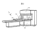
医療コスト低減に最も効果的な方法は入院期間を短縮することである。内視鏡下手術,超音波加熱凝固治療等の低侵襲手術の普及により入院期間の劇的な短縮が期待されている。特に,開口部が広く多方向から患者にアクセスできるMRI装置(例えば,特開平10−57344号公報,特開平10−57345号公報,特開平10−57346号公報:従来技術−1)は,放射線被曝の問題がないことから低侵襲手術実現のための最有力機器と目され,インターベンショナルMRI装置(術中MRI装置)装置の実用化が期待されている。図2は,広い開口部をもつ従来技術のMRI装置の例を示す斜視図であり,上下の方向で対向する,上方に配置される静磁場発生手段210と下方に配置される静磁場発生手段200を示している。
【0004】
従来技術のMRI装置で要求されている静磁場均一度のレベルは,30cm程度の領域で10ppm以下である。一方,不均一な静磁場下でMR画像を取得することを目的として,事前に計測した磁場マップを利用し画像歪みを低減する方法(K.Sekihara:"NMR Imaging for Magnets with Large Nonuniformities",IEEE Trans.Med.Imag.,vol.MI-4,no.4,pp.193-199(1985):従来技術−2)や,RF磁場の動的制御により位置情報を付与する方法(特開平8−322814号公報:従来技術−3,特開平9−019410号公報:従来技術−4)が知られている。
【0005】
【発明が解決しようとする課題】
図2に示す従来技術のMRI装置は,トンネル型の空間に静磁場が形成される一般のMRI装置と比較すると開放度は高いものの,大型の手術道具や超音波加熱凝固治療装置を上方,及び下方に配置されるの静磁場発生手段の間に搬入することは困難であり,さらなる開放度の向上がユーザー(医師)から要求されている。仮りに,図2に示す上方に配置される静磁場発生手段210のない形状とし,下方にのみ配置されるマグネット(静磁場発生手段200)(以下,オープン型マグネットという)を使用して,開放度がより向上したMRI装置(以下,オープン型MRI装置という)が実現すると,大型の手術道具や超音波加熱凝固治療装置の使用が容易となる。
【0006】
オープン型マグネットを使用する場合の最大の課題は,従来技術のMRI装置で要求されているレベルの静磁場均一度(鉛直方向での30cm程度の領域で10ppm以下)を実現する点にある。床上に置かれる下方のマグネットのみを用いるオープン型マグネットでは,静磁場均一度は鉛直方向での20cmの領域でも10%程度となり,現状のMRI装置の約10000倍(4桁)の劣化となる。
【0007】
一般に,静磁場の分布に不均一があると,MR画像の歪みやボケや信号欠落につながるが,静磁場均一度が現状のMRI装置の10000倍に劣化した場合は,核磁気共鳴信号の取得そのものが困難である。従来技術−2,−3,−4の方法を用いれば,現状のMRI装置よりも1桁以上静磁場均一度が劣化しても歪みの小さい画像を取得可能である。しかし,現状のMRI装置よりも4桁静磁場均一度が劣化する場合には,従来技術−2,−3,−4の方法は適用困難である。
【0008】
従来技術−2に示された磁場マップを利用し画像歪みを低減する補正技術は,リードアウト傾斜磁場強度が静磁場の不均一に対して十分大きいことを前提とした補正技術である。このため,傾斜磁場強度を現状と同等とする場合,補正適用の限界は現状よりも1桁程度の静磁場均一度の劣化までである。傾斜磁場強度を強化すれば,より大きな静磁場の不均一を有するマグネットにも適用可能であるが,リードアウト傾斜磁場強度を大きくすると信号受信時に広い計測帯域が必要となる。計測信号のS/Nは計測帯域の0.5乗に比例して劣化する。
【0009】
オープン型マグネットの鉛直方向の静磁場均一度は,現状のMRI装置の静磁場均一度よりも4桁程度劣化するため,オープン型マグネットを使用するオープン型MRI装置では,鉛直方向の位置情報の取得は困難である。オープン型マグネットを使用するオープン型MRI装置では,鉛直方向での静磁場の分布の不均一の改善が課題である。
【0010】
従来技術−3,又は従来技術−4に示されたRF磁場の動的制御により位置情報を付与する方法では,傾斜磁場を用いないため1軸方向については,現状よりも2桁以上静磁場均一度が劣化しても位置情報を取得可能である。しかし,残りの2軸方向については傾斜磁場による位置情報付与が必要であり,残りの2軸方向の位置情報には歪みが生じる。オープン型マグネットを使用するオープン型MRI装置では,正確に位置情報を付与することが大きな課題である。
【0011】
本発明の目的は,上記の課題を解決し,静磁場均一度が劣化しても,S/Nが大きく劣化せず歪みの小さい画像の撮影を可能とし,検査対象が搭載されるベットの下方にのみ配置されるオープン型の磁場発生装置,及び,これを用いるオープン型MRI装置を提供することにある。
【0012】
【課題を解決するための手段】
本発明の磁場発生装置は,MRI装置に於いて検査対象が搭載されるベットの下方にのみ配置され使用される。磁場発生装置は,静磁場を発生する手段として,水平方向の静磁場を発生する,水平方向で対向し磁気的に結合されるマグネット又はコイルの面が水平方向で対向するコイルを具備し,あるいは,鉛直方向の静磁場を発生するマグネット又は静磁場発生コイルを具備する。また,磁場発生装置は,鉛直方向の傾斜磁場を発生する傾斜磁場コイルを具備する。傾斜磁場コイルは,第1のコイルと第1のコイルを取り囲む第2のコイルとから構成され,第1及び第2のコイルは平面上又は曲面上に配置される。傾斜磁場コイルは,静磁場を発生する手段の上又は上方に配置される。
【0013】
第1及び第2のコイルには逆方向の電流が流され,第1のコイルが発生する磁場の方向は,第2のコイルが発生する磁場の方向と逆方向である。第1及び第2のコイルに逆方向の電流を流すことにより,静磁場を発生する手段により発生される静磁場の均一度を改善し,静磁場と鉛直方向の傾斜磁場との合成磁場の均一度を,現状のMRI装置の静磁場均一度に対して2桁以下の劣化に抑える。
【0014】
第1及び第2のコイルは同一の平面上又は同一の曲面上(凹状の曲面又は凸状の曲面)に配置され,あるいは,第1及び第2のコイルの各コイルはそれぞれ異なる平面上又は異なる曲面上に配置される。第1及び第2のコイルは円の形状,あるいは,変形した8の字の形状を有し一方向に不連続部をもつ円の形状をもち,第1及び第2のコイルは同心に配置される。第1及び第2のコイルの半径は15cm以上,35cm以下とする。
【0015】
本発明の磁場発生装置を使用するMRI装置では,各方向に関する位置情報の付与を次のように行なう。受信RFコイルを動的に制御し,受信RFコイルの感度分布を時間軸に沿って複数回変化させて,リードアウト方向に関する位置情報を付与する。静磁場の不均一よりも十分大きい強度(静磁場の不均一よりも少なくとも2桁以上大きな傾き)をもつ傾斜磁場の印加により,残りの2方向(スライス方向,位相エンコード方向)に関する位置情報を付与する。より詳細に説明すると,本発明のMRI装置は,鉛直方向に静磁場を発生する手段と,静磁場が発生された空間で検査対象が搭載されるベットと,第1のコイルと第1のコイルを取り囲む第2のコイルとが平面上又は曲面上に配置され,鉛直方向の傾斜磁場を発生する第1の傾斜磁場コイルと,静磁場の不均一よりも大きい強度をもつスライス方向の傾斜磁場を発生する第2の傾斜磁場コイルと,静磁場の不均一よりも大きい強度をもつ位相エンコード方向の傾斜磁場を発生する第3の傾斜磁場コイルと,感度分布を時間軸に沿って複数回変化させてリードアウト方向に関する位置情報を付与する受信RFコイルとを具備する。本発明のMRI装置では,第1の傾斜磁場コイル及び静磁場を発生する手段はベットの下方に配置され,第1及び第2のコイルには逆方向の電流が流され,第1のコイルが発生する磁場の方向は,第2のコイルが発生する磁場の方向と逆方向である。また,第1及び第2のコイルの半径が15cm以上,35cm以下である。
【0016】
【発明の実施の形態】
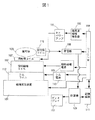
MRI装置は,核磁気共鳴を利用して検査対象の断層像を計測する装置である。図1は,本発明のMRI装置の構成の一例を示す図である。図1に於いて,検査対象(被写体)103は,静磁場を発生する手段及び鉛直方向の傾斜磁場を発生するコイルを具備する磁場発生装置101,及び,鉛直方向に直交する2方向の傾斜磁場を発生する傾斜磁場コイル102の上方に設置される。傾斜磁場コイル102の上方に,検査対象103が搭載されるベッド220,230が配置される。静磁場を発生する手段は,水平方向の静磁場を発生する,水平方向で対向し磁気的に結合されるマグネット又はコイルのなす面が水平方向で対向する1対のコイル,あるいは,鉛直方向の静磁場を発生する,床上に置かれるマグネット又は静磁場発生コイルである。
【0017】
シーケンサ104は,傾斜磁場電源105,RFパルス発生器106に命令を送り,鉛直方向に直交する2方向の傾斜磁場を傾斜磁場コイル102より発生させ,RFパルスを照射用コイル107より発生させる。また,シーケンサ104は,図示しない傾斜磁場電源に命令を送り,鉛直方向の傾斜磁場をコイル41−1,41−2,41’−1,41’−2より発生させる。さらに,シーケンサ104は,図示しない磁場電源に命令を送り,静磁場を1対の静磁場発生コイル91−1,91ー2により発生させる場合もある。
【0018】
通常,RFパルスは,RFパルス発生器106の出力をRFパワーアンプ115により増幅し,照射用コイル107を通じて検査対象103に印加される。検査対象103から発生した核磁気共鳴信号は受信用コイル116により受波される。照射用コイル107は,検査対象103が搭載されるベッド220,230とマグネット300,301(又は,1対の静磁場発生コイル91−1,91ー2)との間の空間,あるいは,ベッド220,230の内部に配置される。受信用コイル116は,検査対象103の検査対象部位(撮影部位)に近接する空間に配置される。
【0019】
受信用コイル116は検査対象103の内部に挿入される場合もある。受信用コイル116により受波された信号は,受信器108により,A/D変換(サンプリング),検波が行われる。検波の基準とする中心周波数(磁気共鳴周波数)は,シーケンサ104によりセットされる。検波された信号は計算機109に送られ,ここでリサンプリング処理された後,画像再構成等の信号処理が行われる。画像再構成等の結果はディスプレイ110に表示される。
【0020】
必要に応じて,記憶媒体111に信号や測定条件を記憶させることもできる。静磁場均一度を調整する必要がある時は,シムコイル112を使う。シムコイル112は複数のチャネルからなり,シム電源113により電流が供給される。静磁場均一度の調整時には,複数のチャネルの各コイルに流れる電流をシーケンサ104により制御する。シーケンサ104はシム電源113に命令を送り,静磁場の不均一を補正する付加的な磁場をシムコイル112より発生させる。
【0021】
なお,シーケンサ104は,各装置がプログラムされたタイミング,強度で動作するように制御を行なう。このプログラムのうち,特にRFパルスの印加,傾斜磁場の印加,核磁気共鳴信号の受信のタイミングや,RFパルスと傾斜磁場の強度を記述したものは撮影シーケンスと呼ばれている。
(第1の実施例)
第1の実施例では,鉛直方向の静磁場を発生するオープン型マグネットを使用する磁場発生装置とこれを用いるオープンMRI装置について説明する。
【0022】
図3は,本発明のオープン型MRI装置の例を示す斜視図である。図3に示すオープンMRI装置では,図2に示す上方の上方に配置される静磁場発生手段210を取り外した外観をもち,床上に置かれ,鉛直方向の静磁場を発生するオープン型マグネット300を磁場発生装置101として使用している。
【0023】
図3に示すように,オープン型マグネット300の鉛直方向の上方に,xy面にフラットな形状をもち検査対象が置かれるベッド220が設置されており,検査対象103の検査対象部位はオープン型マグネット300の上方の5cm〜25cmの空間に配置されている。検査対象103が搭載されるベッド220の天板は天板支持台の上でx,y方向で移動可能である。
【0024】
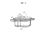
マグネットは検査対象103の下方にのみ存在するため,図11に示すように検査対象103の上方に大型の超音波加熱凝固治療装置999を配置することが可能となる。同様に,レーザー治療装置,手術用ロボットマニュピュレータなどを検査対象103の上方に配置することも可能である。また,オープン型マグネット300とベッド220の位置関係を図12に示すように配置にすれば,装置全体の寸法をよりコンパクトにすることができる。図11,図12に示す構成では,ベッド220に検査対象103は横たわり,オープン型マグネット300の上方の空間に検査対象の検査対象部位が配置される。ベッド220は非磁性体から構成される。検査対象103が搭載されるベッド220の天板は天板支持台の上でx,y方向で移動可能である。
【0025】
ここで,鉛直方向をz軸方向とし,検査対象103の体軸方向をy軸方向とする。オープン型マグネット300のxy面の形状は円形とし,円の半径は50cmとする。円の中心をx=y=0,z方向にはオープン型マグネット300の上端をz=0とし,オープン型マグネット300の上方をz軸の正の方向とする。
【0026】
このオープン型マグネット300では,xy面の中心付近の半径10cmの範囲に於いて,5cm<z<25cmの範囲では,静磁場強度はz軸方向に沿って線形に低下する(z=5cmの位置の静磁場強度が1Tであるとする)。この時,z=25cmの位置の静磁場強度は約0.7Tとなる。z軸方向の静磁場均一度は±約18%であり,現状のMRI装置の静磁場均一度が±10ppmであるとすると,静磁場均一度が4桁以上劣化する。
【0027】
図4は,本発明の第1の実施例の磁場発生装置の構成を示す図であり,円形マグネットと鉛直方向(z軸方向)の傾斜磁場コイルの配置例を示す図である。図4(A)は斜視図,図4(B)は上面図である。
【0028】
z軸方向の静磁場均一度を改善するため,図4に示すように,z軸方向の傾斜磁場コイルを半径の異なる2つのコイル41−1と41−2で構成し,2つのコイルには逆方向の電流を流す。2つのコイルは同心円形であり,コイル41−1の半径は30cm,コイル41−2の半径は20cmとする。2つのコイル41−1,41−2の中心は,円筒形のオープン型マグネット300は円筒の中心軸に一致するように配置されている。z軸方向の傾斜磁場コイル41−1,41−2の上方にベッド220が配置される。
【0029】
図5は,本発明の第1の実施例に於いて,オープン型マグネット300及びコイル41−1,41−2を有する磁場発生装置により生成される磁場の計算例を示す図である。xy面の中心付近の半径10cmの範囲に於いて,5cm<z<25cmの範囲では,2つのコイル41−1,41−2がそれぞれ生成する磁場強度は,z軸方向に沿ってほぼ線形に変化する。コイル41−1の生成する磁場の極性は正であり,コイル41−2の生成する磁場の極性は負であり,コイル41−1,41−2の生成する磁場強度は何れも低下する。この時,コイル41−1がz=5cmの位置で生成する磁場強度が0.43T,コイル41−2がz=5cmの位置で生成する磁場強度が−0.58Tとなるように,コイルに流れる電流を設定する。コイル41−1の巻数を540,コイル41−2の巻数を505とすると,コイル41−1とコイル41−2に流す電流値はいずれも約400Aとなる。
【0030】
オープン型マグネット300の生成する磁場と,コイル41−1,41−2が生成する磁場とを合成した合成磁場について考える。xy面の中心付近の半径10cmの範囲に於いて,5cm<z<25cmの範囲では,合成磁場均一度が向上し,0.85Tを中心として合成磁場均一度は±1000ppm以下となる。この値は,現状のMRI装置の静磁場均一度よりも2桁劣化している。図5に示すように,コイルの生成する磁場は,z軸方向に沿って最初は線形に変化していき,やがてゼロに漸近していく。変曲点のz座標はコイルの寸法が小さいほど小さい。コイル41−1の生成する磁場の極性は正であり,コイル41−2の生成する磁場の極性は負であり,コイル41−1,41−2の生成する磁場強度は何れも低下する。
【0031】
検査対象がベッド220に寝ているとき,検査対象103の厚みは20cm程度であることから,少なくともz<20cmの範囲では合成磁場均一度を向上させたいことから,コイル41−1,41−2の半径の望ましい値は15cmから35cmの範囲である。合成磁場が最も均一な状態を定常状態とし,コイル41−1,41−2に流れる電流を増減させることにより,鉛直方向の傾斜磁場を生成できる。例えば,コイル41−1,41−2に流れる電流をゼロとした場合は,合成磁場はオープン型マグネット300の生成する磁場と等価となる。この時の鉛直方向の傾斜磁場強度は約1500mT/mとなり,現状のMRI装置で用いられている傾斜磁場強度よりも約2桁大きな値である。なお,図4に示したコイル41−1,41−2の形状は円形でなく多角形でも良い。
【0032】
図6は,本発明の第1の実施例に於ける撮影シーケンスの例を示す図である。ここでは,z方向をスライス方向,x方向をリードアウト方向,y方向を位相エンコード方向として選択する。傾斜磁場として,スライス傾斜磁場Gs(z軸方向の傾斜磁場)4と位相エンコード傾斜磁場Ge(y軸方向の傾斜磁場)2を用いる。まず,スライス傾斜磁場4と同時に励起RF磁場1を照射し,所望の厚さを持ったスライス断面の内部に存在する原子核を励起する。
【0033】
上述したように,オープンMRI装置で使用する磁場発生装置による合成磁場均一度は,現状のMRI装置よりも2桁劣化している。このため,現状のMRI装置で用いられているスライス傾斜磁場強度を用いて撮影を行なうと,スライス断面が平面とならず曲面となってしまう。この曲面は不均一な合成磁場の分布に沿った形となる。このことは医師による検査対象の内部の位置情報の把握を著しく阻害する。スライス傾斜磁場強度を現状のMRI装置で用いられている強度よりも2桁増加させることにより,現状のMRI装置で得られるスライス断面と同程度の歪みのスライスを設定できる。
【0034】
2次元画像を取得する方法について説明する。従来技術−3,又は従来技術−4に開示されたRF磁場の動的制御(受信RFコイルの感度分布を時間軸に沿って変化させる動的制御)により,検査対象のリードアウト方向(x方向)の位置情報(プロジェクション)を得る。即ち,受信RFコイル(プローブ)の感度分布を時間軸に沿って複数回変化させながら,FID(free induction decay)信号96を複数回計測して1次元像再構成を行なう。図6では,信号計測の時刻t1,t2,…,tNに於いて,プローブの感度分布を予め設定された関数f1,f2,…,fNとなるように変化させることを示している。受信RFコイルの感度分布に傾斜をもたせるとともにその感度分布を変化させることにより,この感度分布の傾斜方向(リードアウト方向)の位置情報を付与する制御をできる。時間的に変化するプローブの感度分布を表わす関数f1,f2,…,fNにより定義される感度マトリックスの行列式がゼロとならないように感度分布を変化させことにより(従来技術−3),又は,受信RFコイル(プローブ)の感度分布をWavelet基底関数に従って複数回時間的に変化させることにより(従来技術−4),検査対象の特定方向のプロジェクションを再構成できる。
【0035】
傾斜磁場によりリードアウト方向の位置情報を付与する撮影法では,リードアウト傾斜磁場強度を大きくすると信号受信時に広い計測帯域が必要となる。計測信号のS/Nは計測帯域の0.5乗に比例して劣化する。本発明では,リードアウトの位置情報はRF磁場の動的制御(受信RFコイルの感度分布の動的制御)により取得するため,リードアウト傾斜磁場が不要であり,計測帯域を狭くできるため傾斜磁場強度強化に伴うS/N劣化が少ない。
【0036】
再構成される2次元画像の位相エンコード方向の画素数を128とすると,位相エンコード傾斜磁場Ge(2)の印加量を128回ステップ状に変化させ,受信RFコイル(プローブ)の感度分布を時間軸に沿って変化させながら,前述のプロジェクションを求める手順を繰り返す。得られた128個のプロジェクションを位相エンコード傾斜磁場印加方向にフーリエ変換することにより,2次元画像を得る。本発明では3軸方向のうち1軸方向については,RF磁場の動的制御(受信RFコイルの感度分布の動的制御)により位置情報を取得する。その他の2軸方向については,オープン型マグネットを使用する磁場発生装置による合成磁場均一度が現状のMRI装置の静磁場均一度に対して2桁劣化していても,傾斜磁場強度を2桁強化すれば,画像歪みは現状のMRI装置と同程度である。傾斜磁場電源の容量を小さく抑えたい等の理由により,傾斜磁場強度を1桁程度しか強化できない場合は画像に歪みが生じるが,この歪みは従来技術−2により,除去あるいは低減できる。従来技術−2では,まず,不均一な静磁場の分布を事前に計測しておく。不均一な静磁場下で取得したMR画像は,磁場不均一性による画像の歪みと濃度値の変化を含んでいる。静磁場の分布(磁場マップ)を利用し,磁場不均一性の影響(磁場不均一性による画像の歪みと濃度値の変化)を補正し,磁場不均一性の影響を含んだ画像からこれらの影響を除去する。
【0037】
照射RF磁場1のフリップ角を10度以下に設定し,TR(繰り返し時間)を2ミリ秒にすると,256ミリ秒で2次元画像が得られる。あるGe印加量について新たに計測したデータを,1巡前の同じGe印加量のデータと入れ替えながら撮影すれば,リアルタイムに動画を表示することもできる。
【0038】
図6に示す例では,RF磁場の動的制御(受信RFコイルの感度分布の動的制御)により,検査対象のリードアウト方向の位置情報(プロジェクション)を得たが,関心領域(視野)を10cm以下に限れば,従来技術−2に示された磁場マップを利用し画像歪みを低減する補正技術を用いて,歪みの小さい画像を取得可能である。これは関心領域(視野)を小さくすれば,オープン型マグネットを使用する磁場発生装置による合成磁場均一度を現状のMRI装置の静磁場均一度に対して1桁以下の劣化に抑えることが可能なためである。この場合,視野が小さくなるという欠点があるが,感度分布の動的制御が可能な特殊な受信RFコイルが不要となるという効果がある。
【0039】
また,図4に示す例では,上面(xy面)にフラットな形状をもつオープン型マグネット300の上方の空間に検査対象が横たわる例について説明したが,図7に示すように,磁場発生装置101に使用する鉛直方向の静磁場を発生するオープン型マグネット301の上面の形状を凹曲面71の形状とすることにより,合成磁場の均一な空間の領域や,傾斜磁場の線形な空間の領域を広げることが可能である。この場合,先に説明した,磁場発生装置101を構成するマグネット要素,傾斜磁場コイルともに凹曲面71に沿って曲面上に構成する。凹曲面71にフイットする凹曲面をもつベッド230に検査対象103は横たわり,オープン型マグネット301の上方の空間に検査対象の検査対象部位が配置される。ベッド220,230は非磁性体から構成される。検査対象103が搭載されるベッド230の天板は天板支持台の上でx,y方向で移動可能である。
(第2の実施例)
第2の実施例では,水平方向の静磁場を発生する磁場発生装置101について説明する。
【0040】
図8は,本発明の第2の実施例に於ける磁場発生装置101に使用するオープン型マグネットの形状例を示す図である。水平方向の静磁場を発生するオープン型マグネットとしては,図8に示すように,水平方向で対向し磁気的に結合される2つの永久磁石を用いる。永久磁石は,図示しない筐体に囲まれており,その筐体の上方の空間にベッド230を配置する。
【0041】
図9は,本発明の第2の実施例に於ける磁場発生装置に使用する1対の静磁場発生コイル91−1,91−2の配置の例を示す図である。静磁場発生コイル91−1,91−2は,図示しない筐体に囲まれ,かつ,その筐体に支持されており,その筐体の上方の空間にベッド230を配置する。
【0042】
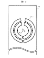
第2の実施例の磁場発生装置101に使用するオープン型マグネット(図8)又は静磁場発生コイル(図9)により発生される静磁場に於いても,鉛直方向(z軸方向)での静磁場均一度は,現状のMRI装置での静磁場の均一度よりも4桁以上劣化する。z軸方向での静磁場均一度を改善するため,図10に示すように,z軸方向の傾斜磁場コイルを半径の異なる2つのコイル41’−1,41’−2で構成し,2つのコイル41’−1,41’−2には逆方向の電流を流す。2つのコイル41’−1,41’−2はそれぞれ,y方向に不連続部をもつ変形した8の字型のコイルであり,全体として円形の形状をもち同心に配置される。コイル41’−1の直径は30cm,コイル41’−2の直径は20cmとする。
【0043】
xy面の中心付近の半径10cmの範囲に於いて,コイル41’−1,41’−2はそれぞれ,x方向と−x方向の磁場を生成する。5cm<z<25cmの範囲では2つのコイル41’−1,41’−2がそれぞれ生成するx方向と−x方向の磁場の強度は,z軸方向に沿ってほぼ線形に変化する。コイル41’−2が生成する磁場の強度は,コイル41’−1が生成する磁場の強度と比較して,z軸方向に沿ってより急峻に変化する。
【0044】
第1の実施例に於ける説明と同様に,2つのコイル41’−1,41’−2に流れる電流を適切に設定することにより,xy面の中心付近の半径10cmの範囲に於いて,5cm<z<25cmの範囲で,マグネット,又は,静磁場発生コイルが生成する磁場と,コイル41’−1,41’−2とが生成する磁場を合成した磁場の均一度,即ち,合成磁場均一度を向上できる。また,この合成磁場が最も均一な状態を定常状態とし,コイル41’−1,41’−2に流れる電流を増減させることにより,鉛直方向の傾斜磁場を生成できる。なお,図10に示したコイル41’−1,41’−2の形状は8の字型であれば良く,全体としての形状は円形でなく多角形でも良い。
【0045】
図8,図9に示す磁場発生装置を用いるオープンMRI装置では,図8に示すように,水平方向で対向する2つの永久磁石の上方の空間,あるいは,図9に示す1対の静磁場発生コイル91−1と91−2の上方の空間に,検査対象103を搭載するベッド230が配置される。磁場発生装置により合成磁場が発生されている空間に検査対象の検査対象部位が配置される。検査対象103が搭載されるベッド230の天板は天板支持台の上で少なくともy方向で移動可能である。
【0046】
水平方向で対向する2つの永久磁石,1対の静磁場発生コイル91−1,91−2は,ベッド230の長軸方向に直交する方向に配置される。図3に示す第1の実施例のオープン型マグネット300を使用する磁場発生装置101と比較すると,図8,図9に示す第2の実施例の磁場発生装置101は,フラットな形状を両側面にもつので,医師は検査対象の側面からのアプローチが容易となるという効果がある。即ち,医師は検査対象の体軸に直交する方向から検査対象にアプローチできる。
【0047】
図8〜図10に示す例では,検査対象103は,図7に示す凹曲面をもつベッド230に横たわるが,図3に示すフラットな形状ベッド220に横たわる構成としても良い。
【0048】
また,第1の実施例に於ける説明と同様に,リードアウト方向についてはRF磁場の動的制御により位置情報を付与する方法により位置情報を取得し,残りの2方向については静磁場の不均一よりも十分大きい強度(静磁場の不均一よりも少なくとも2桁以上大きな傾き)をもつ傾斜磁場により位置情報を付与することにより,2次元画像を得ることができる。
【0049】
以上,本発明を特定の形態について説明したが,上記以外の形態についても同様に,リードアウト方向についてはRF磁場の動的制御により位置情報を付与する方法により位置情報を取得し,残りの2方向については静磁場の不均一よりも十分大きい強度(静磁場の不均一よりも少なくとも2桁以上大きな傾き)をもつ傾斜磁場により位置情報を付与することにより,オープン型MRI装置により検査対象の断層像を得ることができる。
【0050】
また,水平方向又は鉛直方向の静磁場を発生させるマグネットとして,永久磁石,電磁石,超電導磁石を使用できることはいうまでもない。更に,静磁場を発生する手段として,常電導コイル又は超電導コイルが鉛直方向の軸を取り囲み巻かれて構成される,鉛直方向の静磁場を発生する静磁場発生コイルを,ベットの下方の床上に配置して,使用できることはいうまでもない。
【0051】
検査対象の上方に静磁場を発生する手段がないため,大型の手術道具や超音波加熱凝固治療装置を検査対象の上方に設置可能という効果がある。即ち,インターベンショナルMRI装置(術中MRI装置)に於いて,ユーザーニーズに適った装置を提供できるという効果がある。例えば,図6に示した撮影シーケンスでは,2次元画像の取得方法について述べているが,MRI装置の分野で公知の技術により,容易に3次元画像撮影に拡張することが可能である。
【0052】
【発明の効果】
検査対象の下方のみ置かれる磁場発生装置により得られる合成磁場の均一度が劣化しても,S/Nが大きく劣化せず歪みの小さい画像(検査対象の断層像)の撮影を可能とするオープン型MRI装置を提供できる。検査対象の上方に静磁場を発生する手段がないため,大型の手術道具,治療のための装置を検査対象の上方に配置できる。
【図面の簡単な説明】
【図1】本発明のMRI装置の構成の一例を示す図。
【図2】広い開口部をもつ従来技術のMRI装置の例を示す斜視図。
【図3】本発明のオープン型MRI装置の例を示す斜視図。
【図4】本発明の第1の実施例の磁場発生装置の構成を示す図であり,円形マグネットと傾斜磁場コイルの配置例を示す図。
【図5】本発明の第1の実施例に於いて,オープン型マグネット及びコイルを有する磁場発生装置により生成される磁場の計算例を示す図。
【図6】本発明の第1の実施例に於ける撮影シーケンスの例を示す図。
【図7】本発明の第1の実施例に於ける磁場発生装置に使用するオープン型マグネットの形状例を示す図。
【図8】本発明の第2の実施例に於ける磁場発生装置に使用するオープン型マグネットの形状例を示す図。
【図9】本発明の第2の実施例に於ける磁場発生装置に使用する1対の静磁場発生コイルの配置の例を示す図。
【図10】本発明の第2の実施例に適用される傾斜磁場コイルの例を示す図。
【図11】本発明のオープン型MRI装置に超音波加熱凝固治療装置を配置した構成例を示す図。
【図12】本発明のオープン型MRI装置の他の例を示す斜視図。
【符号の説明】
1…励起RFパルス,2…位相エンコード方向の傾斜磁場,4…スライス方向の傾斜磁場,41−1,41−2,41’−1,41’−2…傾斜磁場コイル,71…凹曲面,91−1,91−2…静磁場発生コイル,96…信号,101…磁場発生装置,102…傾斜磁場を発生するコイル,103…検査対象,104…シーケンサ,105…傾斜磁場電源,106…RFパルス発生器,116…プローブ,115…RFパワーアンプ,108…受信器,109…計算機,110…ディスプレイ,111…記憶媒体,112…シムコイル,113…シム電源,200…下方に配置される静磁場発生手段,210…上方に配置される静磁場発生手段,220,230…ベッド,300…上部にフラットな形状をもつオープン型マグネット,301…上部に凹曲面をもつオープン型マグネット。[0001]
BACKGROUND OF THE INVENTION
The present invention relates to an open-type magnetic field generation apparatus disposed only below a bed on which an inspection object is mounted, and an MRI (Magnetic Resonance Imaging) apparatus using the same, and particularly to generation of a magnetic field suitable for an interventional MRI apparatus. It relates to a device and a device.
[0002]
[Prior art]
Terms used in the following description are defined as follows.
“Synthetic magnetic field”: A magnetic field obtained by synthesizing a static magnetic field generated by a means for generating a static magnetic field and a gradient magnetic field in the vertical direction.
“Static magnetic field inhomogeneity”: The difference between the maximum magnetic field strength and the minimum magnetic field strength in the imaging region.
“Static magnetic field homogeneity”: A value obtained by dividing “static magnetic field non-uniformity” by the average magnetic field strength of the static magnetic field in the imaging region.
“Non-uniform composite magnetic field”: The difference between the maximum magnetic field strength and the minimum magnetic field strength of the composite magnetic field in the imaging region.
“Composite magnetic field uniformity”: A value obtained by dividing “composite magnetic field inhomogeneity” by the average magnetic field strength of the composite magnetic field in the imaging region.
[0003]
The most effective way to reduce medical costs is to shorten hospital stays. With the spread of minimally invasive surgery such as endoscopic surgery and ultrasonic heat coagulation, hospitalization is expected to be dramatically shortened. In particular, an MRI apparatus (for example, JP-A-10-57344, JP-A-10-57345, JP-A-10-57346: Prior Art-1), which has a wide opening and allows access to a patient from multiple directions, Since there is no problem of exposure, it is regarded as the most powerful device for realizing minimally invasive surgery, and the practical application of an interventional MRI apparatus (intraoperative MRI apparatus) is expected. FIG. 2 is a perspective view showing an example of a prior art MRI apparatus having a wide opening. The static magnetic field generating means 210 disposed above and the static magnetic field generating means disposed below facing each other in the vertical direction. 200 is shown.
[0004]
The level of static magnetic field homogeneity required in the conventional MRI apparatus is 10 ppm or less in a region of about 30 cm. On the other hand, for the purpose of acquiring MR images under a non-uniform static magnetic field, a method for reducing image distortion using a magnetic field map measured in advance (K.Sekihara: "NMR Imaging for Magnets with Large Nonuniformities", IEEE Trans.Med.Imag., Vol.MI-4, no.4, pp.193-199 (1985): Prior Art-2) and a method for providing position information by dynamic control of an RF magnetic field (Japanese Patent Laid-Open No. 8) No. 322814: Prior Art-3, Japanese Patent Laid-Open No. 9-019410: Prior Art-4) are known.
[0005]
[Problems to be solved by the invention]
The conventional MRI apparatus shown in FIG. 2 has a high degree of openness compared with a general MRI apparatus in which a static magnetic field is formed in a tunnel-type space, but a large surgical tool and an ultrasonic heating coagulation treatment apparatus are located above, and It is difficult to carry in between the static magnetic field generating means disposed below, and further improvement in the degree of openness is demanded by the user (doctor). Temporarily, it is made into the shape without the static magnetic field generation means 210 arrange | positioned upwards shown in FIG. 2, and it opens using the magnet (static magnetic field generation means 200) (henceforth an open type magnet) arrange | positioned only below. When an improved MRI apparatus (hereinafter referred to as an open type MRI apparatus) is realized, it becomes easy to use a large surgical tool and an ultrasonic heat coagulation treatment apparatus.
[0006]
The biggest problem when using an open-type magnet is to achieve the level of static magnetic field homogeneity (10 ppm or less in a region of about 30 cm in the vertical direction) required by a conventional MRI apparatus. In the open type magnet using only the lower magnet placed on the floor, the static magnetic field uniformity is about 10% even in the 20 cm region in the vertical direction, which is about 10000 times (four digits) degradation of the current MRI apparatus.
[0007]
In general, if the distribution of the static magnetic field is not uniform, the MR image may be distorted, blurred, or missing a signal. However, if the static magnetic field uniformity deteriorates 10,000 times that of the current MRI apparatus, the acquisition of nuclear magnetic resonance signals That is difficult. By using the methods of the prior art-2, -3, and -4, it is possible to acquire an image with a small distortion even if the static magnetic field uniformity is deteriorated by one digit or more as compared with the current MRI apparatus. However, when the 4-digit static magnetic field uniformity is deteriorated as compared with the current MRI apparatus, it is difficult to apply the methods of the prior art-2, -3, and -4.
[0008]
The correction technique for reducing the image distortion using the magnetic field map shown in the prior art-2 is a correction technique based on the premise that the readout gradient magnetic field strength is sufficiently large against the non-uniformity of the static magnetic field. For this reason, when the gradient magnetic field strength is made equal to the current level, the limit of the application of correction is to the degradation of the static magnetic field uniformity by about an order of magnitude from the current level. If the gradient magnetic field strength is strengthened, it can be applied to a magnet having a larger static magnetic field inhomogeneity, but if the readout gradient magnetic field strength is increased, a wide measurement band is required for signal reception. The S / N of the measurement signal deteriorates in proportion to the 0.5th power of the measurement band.
[0009]
Since the static magnetic field uniformity in the vertical direction of open magnets is about four orders of magnitude worse than the static magnetic field uniformity of current MRI devices, the open MRI device that uses open magnets acquires vertical position information. It is difficult. In an open MRI apparatus using an open magnet, improvement of non-uniform distribution of the static magnetic field in the vertical direction is a problem.
[0010]
In the method of assigning position information by dynamic control of the RF magnetic field shown in the prior art-3 or the prior art-4, the gradient magnetic field is not used, so that the static magnetic field uniformity is more than two orders of magnitude in the uniaxial direction. Even if it deteriorates once, the position information can be acquired. However, it is necessary to provide position information by a gradient magnetic field for the remaining two-axis directions, and the remaining two-axis direction position information is distorted. In an open type MRI apparatus using an open type magnet, it is a big problem to provide position information accurately.
[0011]
The object of the present invention is to solve the above-mentioned problems, and even if the static magnetic field uniformity is deteriorated, the S / N is not greatly deteriorated and an image with a small distortion can be taken. It is an object to provide an open type magnetic field generation apparatus arranged only in the above and an open type MRI apparatus using the same.
[0012]
[Means for Solving the Problems]
The magnetic field generator of the present invention is used by being disposed only below the bed on which the inspection object is mounted in the MRI apparatus. The magnetic field generator includes, as means for generating a static magnetic field, a horizontal static magnetic field, a horizontally opposed and magnetically coupled magnet or a coil whose coil faces are horizontally opposed, or , A magnet for generating a vertical static magnetic field or a static magnetic field generating coil is provided. The magnetic field generator includes a gradient magnetic field coil that generates a vertical gradient magnetic field. The gradient coil is composed of a first coil and a second coil surrounding the first coil, and the first and second coils are arranged on a plane or a curved surface. The gradient coil is arranged above or above the means for generating a static magnetic field.
[0013]
A current in the opposite direction is passed through the first and second coils, and the direction of the magnetic field generated by the first coil is opposite to the direction of the magnetic field generated by the second coil. By flowing currents in opposite directions through the first and second coils, the uniformity of the static magnetic field generated by the means for generating the static magnetic field is improved, and the uniformity of the combined magnetic field of the static magnetic field and the vertical gradient magnetic field is improved. Once, the deterioration of the static magnetic field uniformity of the current MRI apparatus is reduced to two orders of magnitude or less.
[0014]
The first and second coils are arranged on the same plane or on the same curved surface (concave curved surface or convex curved surface), or the coils of the first and second coils are on different planes or different from each other. Arranged on a curved surface. The first and second coils have a circular shape or a circular shape with a deformed figure 8 shape and a discontinuity in one direction, and the first and second coils are arranged concentrically. The The radius of the first and second coils is 15 cm or more and 35 cm or less.
[0015]
In the MRI apparatus using the magnetic field generation apparatus of the present invention, position information regarding each direction is given as follows. The receiving RF coil is dynamically controlled, the sensitivity distribution of the receiving RF coil is changed a plurality of times along the time axis, and position information regarding the readout direction is given. Position information on the remaining two directions (slice direction and phase encoding direction) is applied by applying a gradient magnetic field having a strength sufficiently larger than the non-uniformity of the static magnetic field (at least two orders of magnitude greater than the non-uniformity of the static magnetic field). To do. More specifically, the MRI apparatus of the present invention includes means for generating a static magnetic field in the vertical direction, a bed on which an inspection object is mounted in a space where the static magnetic field is generated, a first coil, and a first coil. A second coil that surrounds the first gradient coil that generates a vertical gradient magnetic field and a gradient magnetic field in the slice direction that has a strength greater than the static magnetic field non-uniformity. A second gradient coil that is generated, a third gradient coil that generates a gradient magnetic field in the phase encoding direction having a strength greater than the non-uniformity of the static magnetic field, and the sensitivity distribution is changed a plurality of times along the time axis. And a receiving RF coil for providing position information regarding the lead-out direction. In the MRI apparatus of the present invention, the first gradient coil and the means for generating the static magnetic field are arranged below the bed, and a current in the reverse direction is passed through the first and second coils, The direction of the generated magnetic field is opposite to the direction of the magnetic field generated by the second coil. Further, the radius of the first and second coils is 15 cm or more and 35 cm or less.
[0016]
DETAILED DESCRIPTION OF THE INVENTION
The MRI apparatus is an apparatus that measures a tomographic image to be examined using nuclear magnetic resonance. FIG. 1 is a diagram showing an example of the configuration of the MRI apparatus of the present invention. In FIG. 1, an inspection object (subject) 103 includes a magnetic field generator 101 having means for generating a static magnetic field, a coil for generating a vertical gradient magnetic field, and a two-direction gradient magnetic field orthogonal to the vertical direction. Is installed above the gradient
[0017]
The
[0018]
Normally, the RF pulse is amplified by the
[0019]
The receiving
[0020]
If necessary, signals and measurement conditions can be stored in the
[0021]
The
(First embodiment)
In the first embodiment, a magnetic field generator using an open magnet that generates a vertical static magnetic field and an open MRI apparatus using the magnetic field generator will be described.
[0022]
FIG. 3 is a perspective view showing an example of the open type MRI apparatus of the present invention. The open MRI apparatus shown in FIG. 3 has an appearance in which the static magnetic field generating means 210 disposed above the upper part shown in FIG. 2 is removed, and an
[0023]
As shown in FIG. 3, a
[0024]
Since the magnet exists only below the
[0025]
Here, the vertical direction is the z-axis direction, and the body axis direction of the
[0026]
In the
[0027]
FIG. 4 is a diagram showing the configuration of the magnetic field generator of the first embodiment of the present invention, and is a diagram showing an arrangement example of a circular magnet and a gradient magnetic field coil in the vertical direction (z-axis direction). 4A is a perspective view, and FIG. 4B is a top view.
[0028]
In order to improve the static magnetic field uniformity in the z-axis direction, the gradient magnetic field coil in the z-axis direction is composed of two coils 41-1 and 41-2 having different radii as shown in FIG. Apply current in the reverse direction. The two coils are concentric circles, and the radius of the coil 41-1 is 30 cm and the radius of the coil 41-2 is 20 cm. The centers of the two coils 41-1 and 41-2 are arranged so that the cylindrical
[0029]
FIG. 5 is a diagram showing a calculation example of the magnetic field generated by the magnetic field generator having the
[0030]
Consider a synthesized magnetic field obtained by synthesizing the magnetic field generated by the
[0031]
Since the thickness of the
[0032]
FIG. 6 is a diagram showing an example of a photographing sequence in the first embodiment of the present invention. Here, the z direction is selected as the slice direction, the x direction is selected as the readout direction, and the y direction is selected as the phase encoding direction. As the gradient magnetic field, a slice gradient magnetic field Gs (gradient magnetic field in the z-axis direction) 4 and a phase encode gradient magnetic field Ge (gradient magnetic field in the y-axis direction) 2 are used. First, the excitation RF
[0033]
As described above, the synthesized magnetic field uniformity by the magnetic field generator used in the open MRI apparatus is deteriorated by two orders of magnitude compared to the current MRI apparatus. For this reason, when imaging is performed using the slice gradient magnetic field strength used in the current MRI apparatus, the slice cross-section becomes a curved surface instead of a flat surface. This curved surface follows a non-uniform distribution of the synthetic magnetic field. This significantly hinders the grasp of the position information inside the examination object by the doctor. By increasing the slice gradient magnetic field strength by two orders of magnitude over the strength used in the current MRI apparatus, a slice having the same degree of distortion as the slice cross section obtained by the current MRI apparatus can be set.
[0034]
A method for acquiring a two-dimensional image will be described. The readout direction (x direction) of the inspection object by the dynamic control of the RF magnetic field (dynamic control for changing the sensitivity distribution of the reception RF coil along the time axis) disclosed in the prior art-3 or the prior art-4. ) Position information (projection). That is, one-dimensional image reconstruction is performed by measuring a FID (free induction decay) signal 96 a plurality of times while changing the sensitivity distribution of the reception RF coil (probe) a plurality of times along the time axis. FIG. 6 shows that the sensitivity distribution of the probe is changed to become preset functions f1, f2,..., FN at signal measurement times t1, t2,. By giving a gradient to the sensitivity distribution of the reception RF coil and changing the sensitivity distribution, it is possible to control to give position information in the gradient direction (lead-out direction) of the sensitivity distribution. By changing the sensitivity distribution so that the determinant of the sensitivity matrix defined by the functions f1, f2,..., FN representing the sensitivity distribution of the probe that changes with time is not zero (prior art-3), or By changing the sensitivity distribution of the reception RF coil (probe) over time according to the Wavelet basis function (prior art-4), the projection in a specific direction to be inspected can be reconstructed.
[0035]
In an imaging method in which position information in the readout direction is given by a gradient magnetic field, if the readout gradient magnetic field strength is increased, a wide measurement band is required at the time of signal reception. The S / N of the measurement signal deteriorates in proportion to the 0.5th power of the measurement band. In the present invention, since the readout position information is obtained by dynamic control of the RF magnetic field (dynamic control of the sensitivity distribution of the receiving RF coil), the readout gradient magnetic field is unnecessary and the measurement band can be narrowed, so that the gradient magnetic field can be reduced. There is little S / N deterioration accompanying strength reinforcement.
[0036]
Assuming that the number of pixels in the phase encoding direction of the reconstructed two-dimensional image is 128, the application amount of the phase encoding gradient magnetic field Ge (2) is changed 128 times stepwise, and the sensitivity distribution of the reception RF coil (probe) is changed over time. Repeat the procedure for finding the projection as it varies along the axis. A two-dimensional image is obtained by Fourier transforming the obtained 128 projections in the phase encoding gradient magnetic field application direction. In the present invention, position information is acquired for one of the three axes by dynamic control of the RF magnetic field (dynamic control of the sensitivity distribution of the reception RF coil). For the other two-axis directions, the gradient magnetic field strength is enhanced by two orders of magnitude even if the synthesized magnetic field uniformity by the magnetic field generator using open magnets deteriorates by two orders of magnitude compared to the static magnetic field uniformity of the current MRI equipment. If so, the image distortion is comparable to that of the current MRI apparatus. If the gradient magnetic field strength can be enhanced only by an order of magnitude for the purpose of reducing the capacity of the gradient magnetic field power source or the like, the image will be distorted, but this distortion can be removed or reduced by Conventional Technique-2. In the prior art-2, first, the distribution of the non-uniform static magnetic field is measured in advance. An MR image acquired under a non-uniform static magnetic field includes image distortion and density value change due to magnetic field non-uniformity. Using the distribution of the static magnetic field (magnetic field map), the effects of magnetic field inhomogeneities (image distortion and changes in density values due to magnetic field inhomogeneities) are corrected, and images containing the effects of magnetic field inhomogeneities are used to correct these. Remove the effect.
[0037]
When the flip angle of the irradiation RF
[0038]
In the example shown in FIG. 6, positional information (projection) in the readout direction of the inspection object is obtained by dynamic control of the RF magnetic field (dynamic control of the sensitivity distribution of the reception RF coil). If it is limited to 10 cm or less, it is possible to acquire an image with small distortion by using a correction technique for reducing image distortion by using the magnetic field map shown in Conventional Technique-2. If the region of interest (field of view) is reduced, the synthesized magnetic field uniformity by the magnetic field generator using an open magnet can be suppressed to one order of magnitude or less compared to the static magnetic field uniformity of the current MRI apparatus. Because. In this case, there is a disadvantage that the field of view becomes small, but there is an effect that a special reception RF coil capable of dynamic control of the sensitivity distribution becomes unnecessary.
[0039]
In the example shown in FIG. 4, the example in which the inspection object lies in the space above the
(Second embodiment)
In the second embodiment, a magnetic field generator 101 that generates a horizontal static magnetic field will be described.
[0040]
FIG. 8 is a diagram showing an example of the shape of an open magnet used in the magnetic field generator 101 in the second embodiment of the present invention. As an open type magnet for generating a static magnetic field in the horizontal direction, as shown in FIG. 8, two permanent magnets facing each other in the horizontal direction and magnetically coupled are used. The permanent magnet is surrounded by a casing (not shown), and the
[0041]
FIG. 9 is a diagram showing an example of the arrangement of a pair of static magnetic field generating coils 91-1 and 91-2 used in the magnetic field generator in the second embodiment of the present invention. The static magnetic field generating coils 91-1 and 91-2 are surrounded by a casing (not shown) and supported by the casing, and the
[0042]
Even in the static magnetic field generated by the open-type magnet (FIG. 8) or the static magnetic field generating coil (FIG. 9) used in the magnetic field generator 101 of the second embodiment, static in the vertical direction (z-axis direction) is also obtained. The magnetic field uniformity is deteriorated by four orders of magnitude or more than the static magnetic field uniformity in the current MRI apparatus. In order to improve the static magnetic field uniformity in the z-axis direction, the gradient magnetic field coil in the z-axis direction is composed of two coils 41'-1 and 41'-2 having different radii as shown in FIG. A current in the reverse direction is passed through the coils 41'-1 and 41'-2. Each of the two
[0043]
In the range of a radius of 10 cm near the center of the xy plane, the coils 41'-1 and 41'-2 generate magnetic fields in the x direction and the -x direction, respectively. In the range of 5 cm <z <25 cm, the magnetic field strengths in the x and −x directions generated by the two
[0044]
Similar to the description in the first embodiment, by appropriately setting the currents flowing through the two
[0045]
In the open MRI apparatus using the magnetic field generator shown in FIGS. 8 and 9, as shown in FIG. 8, the space above two permanent magnets facing each other in the horizontal direction, or a pair of static magnetic fields generated in FIG. A
[0046]
Two permanent magnets and a pair of static magnetic field generating coils 91-1 and 91-2 that face each other in the horizontal direction are arranged in a direction orthogonal to the major axis direction of the
[0047]
In the example shown in FIGS. 8 to 10, the
[0048]
Similarly to the description in the first embodiment, in the readout direction, the position information is obtained by the method of providing the position information by dynamic control of the RF magnetic field, and the static magnetic field is not obtained in the remaining two directions. A two-dimensional image can be obtained by providing position information with a gradient magnetic field having a strength sufficiently larger than uniform (a gradient larger by at least two orders of magnitude than non-uniformity of a static magnetic field).
[0049]
As described above, the present invention has been described with respect to a specific form. Similarly, with respect to other forms than the above, the position information is obtained by a method of assigning position information by dynamic control of the RF magnetic field in the readout direction, and the remaining two. By applying position information with a gradient magnetic field that has a strength sufficiently greater than the non-uniformity of the static magnetic field (at least two orders of magnitude greater than the non-uniformity of the static magnetic field), the tomographic object to be inspected by an open MRI system An image can be obtained.
[0050]
Needless to say, a permanent magnet, an electromagnet, or a superconducting magnet can be used as a magnet for generating a horizontal or vertical static magnetic field. Furthermore, as a means for generating a static magnetic field, a static magnetic field generating coil for generating a static magnetic field in the vertical direction, in which a normal conducting coil or a superconducting coil is wrapped around a vertical axis, is provided on the floor below the bed. Needless to say, it can be deployed and used.
[0051]
Since there is no means for generating a static magnetic field above the inspection object, there is an effect that a large surgical tool or an ultrasonic heating coagulation treatment apparatus can be installed above the inspection object. In other words, the interventional MRI apparatus (intraoperative MRI apparatus) can provide an apparatus suitable for user needs. For example, although the imaging sequence shown in FIG. 6 describes a method for acquiring a two-dimensional image, it can be easily extended to three-dimensional imaging by a technique known in the field of MRI apparatuses.
[0052]
【The invention's effect】
Open that enables to take images with small distortion (tomographic image to be inspected) without greatly degrading S / N even if the uniformity of the synthetic magnetic field obtained by the magnetic field generator placed only under the inspection target is deteriorated A type MRI apparatus can be provided. Since there is no means for generating a static magnetic field above the inspection object, a large surgical tool and a treatment device can be arranged above the inspection object.
[Brief description of the drawings]
FIG. 1 is a diagram showing an example of the configuration of an MRI apparatus of the present invention.
FIG. 2 is a perspective view showing an example of a prior art MRI apparatus having a wide opening.
FIG. 3 is a perspective view showing an example of an open type MRI apparatus of the present invention.
FIG. 4 is a diagram showing the configuration of the magnetic field generator of the first embodiment of the present invention, and is a diagram showing an arrangement example of a circular magnet and a gradient magnetic field coil.
FIG. 5 is a diagram showing a calculation example of a magnetic field generated by a magnetic field generator having an open magnet and a coil in the first embodiment of the present invention.
FIG. 6 is a diagram showing an example of a photographing sequence in the first embodiment of the present invention.
FIG. 7 is a view showing an example of the shape of an open magnet used in the magnetic field generator in the first embodiment of the present invention.
FIG. 8 is a view showing an example of the shape of an open type magnet used in a magnetic field generator in a second embodiment of the present invention.
FIG. 9 is a diagram showing an example of the arrangement of a pair of static magnetic field generating coils used in the magnetic field generation apparatus according to the second embodiment of the present invention.
FIG. 10 is a diagram showing an example of a gradient magnetic field coil applied to the second embodiment of the present invention.
FIG. 11 is a diagram showing a configuration example in which an ultrasonic heating coagulation treatment apparatus is arranged in the open type MRI apparatus of the present invention.
FIG. 12 is a perspective view showing another example of the open type MRI apparatus of the present invention.
[Explanation of symbols]
DESCRIPTION OF
Claims (13)
前記静磁場を発生する手段と,前記傾斜磁場コイルとは , 前記ベットの下方のみに配置され,前記第1のコイルが発生する磁場の方向が前記第2のコイルが発生する磁場の方向と逆方向であり , 前記静磁場を発生する手段の上面の形状は凹曲面であり , 前記傾斜磁場コイルは前記凹曲面に沿って配置されることを特徴とする磁場発生装置。It means for generating a static magnetic field, a first coil and a gradient coil comprises a second coil surrounding a first coil generating a gradient magnetic field in the vertical direction, and the bed is mounted inspected Possess ,
And means for generating the static magnetic field, the gradient magnetic field coil is arranged only below the bet, the direction opposite to the magnetic field direction of the magnetic field which the first coil generates said second coil generates is the direction, the shape of the upper surface of the means for generating the static magnetic field is concavely curved surface, the magnetic field generating apparatus wherein the gradient coil is characterized in that it is arranged along the concave curved surface.
前記静磁場を発生する手段と,前記傾斜磁場コイルとは,前記ベットの下方のみに配置され,前記2つのコイルが発生する磁場の方向が逆方向であり, 前記静磁場を発生する手段の上面の形状は凹曲面であり,前記傾斜磁場コイルは前記凹曲面に沿って配置されることを特徴とする磁場発生装置。A means for generating a horizontal or vertical static magnetic field, a gradient magnetic field coil having two circular coils having different radii and generating a gradient magnetic field in the vertical direction, and a bed on which an inspection object is mounted,
The means for generating the static magnetic field and the gradient magnetic field coil are arranged only below the bed, the direction of the magnetic field generated by the two coils is opposite, and the upper surface of the means for generating the static magnetic field Is a concave curved surface, and the gradient magnetic field coil is arranged along the concave curved surface.
Priority Applications (2)
| Application Number | Priority Date | Filing Date | Title |
|---|---|---|---|
| JP2001312117A JP4045769B2 (en) | 2001-10-10 | 2001-10-10 | Magnetic field generator and MRI apparatus using the same |
| US10/242,442 US7358726B2 (en) | 2001-10-10 | 2002-09-13 | System of generating a magnetic field and MRI system using the system of generating a magnetic field |
Applications Claiming Priority (1)
| Application Number | Priority Date | Filing Date | Title |
|---|---|---|---|
| JP2001312117A JP4045769B2 (en) | 2001-10-10 | 2001-10-10 | Magnetic field generator and MRI apparatus using the same |
Publications (3)
| Publication Number | Publication Date |
|---|---|
| JP2003116812A JP2003116812A (en) | 2003-04-22 |
| JP2003116812A5 JP2003116812A5 (en) | 2005-05-26 |
| JP4045769B2 true JP4045769B2 (en) | 2008-02-13 |
Family
ID=19130828
Family Applications (1)
| Application Number | Title | Priority Date | Filing Date |
|---|---|---|---|
| JP2001312117A Expired - Fee Related JP4045769B2 (en) | 2001-10-10 | 2001-10-10 | Magnetic field generator and MRI apparatus using the same |
Country Status (2)
| Country | Link |
|---|---|
| US (1) | US7358726B2 (en) |
| JP (1) | JP4045769B2 (en) |
Families Citing this family (5)
| Publication number | Priority date | Publication date | Assignee | Title |
|---|---|---|---|---|
| US7343192B2 (en) * | 2003-09-23 | 2008-03-11 | Echo Medical Systems, Llc | Magnetic resonance imaging method and apparatus for body composition analysis |
| CN1934458A (en) * | 2004-03-17 | 2007-03-21 | 皇家飞利浦电子股份有限公司 | Dynamic shimset calibration for B0 offset |
| CN100563752C (en) * | 2005-01-31 | 2009-12-02 | 重庆融海超声医学工程研究中心有限公司 | The ultrasonic treatment unit of MRI guiding |
| US9766317B2 (en) * | 2011-10-25 | 2017-09-19 | New York University | Apparatus, systems and methods which are based on magnetic resonance imaging for evaluation(s) of radio frequency emitting device(s) |
| US20190099490A1 (en) * | 2017-10-04 | 2019-04-04 | Weinberg Medical Physics, Inc. | Apparatus and method for magnetic delivery of drugs deep into articular cartilage for osteoarthritis |
Family Cites Families (41)
| Publication number | Priority date | Publication date | Assignee | Title |
|---|---|---|---|---|
| GB8410972D0 (en) * | 1984-04-30 | 1984-06-06 | Oxford Magnet Tech | Magnet assembly |
| US4721914A (en) * | 1984-05-01 | 1988-01-26 | The United States Of America As Represented By The United States Department Of Energy | Apparatus for unilateral generation of a homogeneous magnetic field |
| US4714881A (en) * | 1986-07-15 | 1987-12-22 | Mobil Oil Corporation | Nuclear magnetic resonance borehole logging tool |
| US4829252A (en) * | 1987-10-28 | 1989-05-09 | The Regents Of The University Of California | MRI system with open access to patient image volume |
| GB8827271D0 (en) | 1988-11-22 | 1988-12-29 | Oxford Magnet Tech | Magnetic field generating assembly |
| DE4037894A1 (en) * | 1989-12-11 | 1991-06-13 | Siemens Ag | CORE SPIN TOMOGRAPH |
| EP0476321B1 (en) * | 1990-09-20 | 1996-10-23 | Siemens Aktiengesellschaft | Nuclear spin tomograph |
| US5245286A (en) * | 1991-04-18 | 1993-09-14 | The Regents Of The University Of California | Apparatus and method for stabilizing the background magnetic field during mri |
| GB9302837D0 (en) * | 1993-02-12 | 1993-03-31 | Oxford Instr Uk Ltd | Magnet assembly |
| US5596303A (en) * | 1993-02-22 | 1997-01-21 | Akguen Ali | Superconductive magnet system with low and high temperature superconductors |
| DE4422781C1 (en) * | 1994-06-29 | 1996-02-01 | Siemens Ag | Actively screened planar gradient coil for pole plate magnets |
| US5630415A (en) * | 1995-01-19 | 1997-05-20 | The Regents Of The University Of California | Rigidized gradient coil |
| JP3375792B2 (en) | 1995-07-03 | 2003-02-10 | 株式会社日立製作所 | RF probe and inspection apparatus using nuclear magnetic resonance using the same |
| JP3490542B2 (en) | 1995-05-31 | 2004-01-26 | 株式会社日立製作所 | Inspection device using nuclear magnetic resonance |
| US5808467A (en) | 1995-05-31 | 1998-09-15 | Hitachi, Ltd. | RF probe and inspection system using NMR using the same |
| US5842986A (en) * | 1995-08-16 | 1998-12-01 | Proton Sciences Corp. | Ferromagnetic foreign body screening method and apparatus |
| KR100311073B1 (en) * | 1996-02-26 | 2001-12-28 | 윤종용 | Magnetic resonance imaging system |
| DE19620926C2 (en) * | 1996-05-24 | 2001-08-09 | Bruker Analytik Gmbh | Magnet arrangement for an NMR tomography system, in particular for skin and surface examinations, method for producing the magnet arrangement and gradient coil system |
| US5744960A (en) * | 1996-08-08 | 1998-04-28 | Brigham And Women's Hospital | Planar open magnet MRI system |
| FR2754066B1 (en) * | 1996-10-01 | 1998-10-30 | Oreal | DEVICE FOR EXAMINING A LOW DEPTH VOLUME BY NUCLEAR MAGNETIC RESONANCE |
| US5677630A (en) * | 1996-10-21 | 1997-10-14 | General Electric Company | Planar superconducting MRI magnet |
| ATE419789T1 (en) * | 1997-05-23 | 2009-01-15 | Prorhythm Inc | HIGH INTENSITY DISPOSABLE FOCUSING ULTRASONIC APPLICATOR |
| US5914600A (en) * | 1997-06-04 | 1999-06-22 | Brigham And Women's Hospital | Planar open solenoidal magnet MRI system |
| JP3104863B2 (en) | 1997-07-11 | 2000-10-30 | 株式会社日立メディコ | Magnetic resonance imaging equipment |
| JPH1057346A (en) | 1997-07-11 | 1998-03-03 | Hitachi Medical Corp | Magnetic resonance imaging apparatus |
| JPH1057344A (en) | 1997-07-11 | 1998-03-03 | Hitachi Medical Corp | Magnetic resonance imaging apparatus |
| WO1999017656A1 (en) * | 1997-10-07 | 1999-04-15 | The Board Of Trustees Of The Leland Stanford Junior University | Methods for view angle tilt imaging of interventional devices providing adjustment of device contrast |
| US6144204A (en) * | 1997-11-28 | 2000-11-07 | Picker Nordstar Oy | Gradient coils for magnetic resonance meeting |
| IT1304768B1 (en) * | 1998-10-05 | 2001-03-29 | Esaote Spa | TABLE FOR PATIENT HOLDER OR SIMILAR, AND MACHINE, IN PARTICULAR MACHINE FOR DETECTION OF IMAGES IN NUCLEAR MAGNETIC RESONANCE IN |
| US6208142B1 (en) * | 1998-12-07 | 2001-03-27 | Transurgical, Inc. | Magnetic resonance apparatus and methods with shim adjustment |
| US6278351B1 (en) * | 1999-01-11 | 2001-08-21 | Transurgical, Inc. | Multi-coil MRI magnet |
| JP3454235B2 (en) * | 1999-10-06 | 2003-10-06 | 株式会社日立製作所 | Biomagnetic field measurement device |
| US6335670B1 (en) * | 2000-04-14 | 2002-01-01 | Marconi Medical Systems Finland, Inc. | Mri system with split rose ring with high homogeneity |
| JP3705995B2 (en) * | 2000-04-19 | 2005-10-12 | ジーイー・メディカル・システムズ・グローバル・テクノロジー・カンパニー・エルエルシー | Gradient coil manufacturing method, gradient coil, and magnetic resonance imaging apparatus |
| WO2002002010A1 (en) * | 2000-07-05 | 2002-01-10 | Hitachi Medical Corporation | Magnetic resonance imaging device and gradient magnetic field coil used for it |
| JP3712349B2 (en) * | 2000-07-18 | 2005-11-02 | 独立行政法人科学技術振興機構 | Surviving myocardial diagnostic apparatus and operating method thereof |
| JP3987686B2 (en) * | 2001-02-02 | 2007-10-10 | ジーイー・メディカル・システムズ・グローバル・テクノロジー・カンパニー・エルエルシー | Static magnetic field correction method and MRI apparatus |
| US7034537B2 (en) * | 2001-03-14 | 2006-04-25 | Hitachi Medical Corporation | MRI apparatus correcting vibratory static magnetic field fluctuations, by utilizing the static magnetic fluctuation itself |
| ITSV20020057A1 (en) * | 2002-11-28 | 2004-05-29 | Esaote Spa | COMBINATION OF NUCLEAR RESONANCE IMAGE DETECTION MACHINE AND PATIENT HOLDER TABLE |
| DE10354228B3 (en) * | 2003-11-20 | 2005-09-22 | Siemens Ag | A gradient coil radio frequency antenna unit and a magnetic resonance apparatus having a gradient coil radio frequency antenna unit |
| CN100350522C (en) * | 2004-05-18 | 2007-11-21 | 北京泰杰磁电研究所 | Magnetic resonant image-forming magnetic body and forming method thereof |
-
2001
- 2001-10-10 JP JP2001312117A patent/JP4045769B2/en not_active Expired - Fee Related
-
2002
- 2002-09-13 US US10/242,442 patent/US7358726B2/en not_active Expired - Fee Related
Also Published As
| Publication number | Publication date |
|---|---|
| JP2003116812A (en) | 2003-04-22 |
| US20030069497A1 (en) | 2003-04-10 |
| US7358726B2 (en) | 2008-04-15 |
Similar Documents
| Publication | Publication Date | Title |
|---|---|---|
| Marques et al. | Low‐field MRI: An MR physics perspective | |
| US6445182B1 (en) | Geometric distortion correction in magnetic resonance imaging | |
| US6975896B2 (en) | Fiducial markers for MRI | |
| JP4188384B2 (en) | Magnetic resonance imaging system | |
| RU2622481C2 (en) | Background removal when receiving images by using magnetic particles | |
| JP5624028B2 (en) | Magnetic resonance imaging apparatus and superconducting quantum interference device detection and method using magnetic field circulation method | |
| US6876198B2 (en) | Magnetic resonance imaging system | |
| US11660016B2 (en) | Single-sided 3D magnet and magnetic resonance imaging (MRI) system | |
| JPH0222649B2 (en) | ||
| JP4247948B2 (en) | Magnet apparatus and MRI apparatus | |
| JP2019512083A (en) | MRI imaging system using permanent magnet array | |
| JP2015500725A (en) | Use of gradient coils to correct higher order BO field inhomogeneities in MR imaging | |
| US11243277B2 (en) | Passive field camera and method for operating the passive field camera | |
| GB2445759A (en) | Magnetic resonance imaging scanner | |
| JP4045769B2 (en) | Magnetic field generator and MRI apparatus using the same | |
| US20210116525A1 (en) | Hybrid mpi and mri/ct imaging apparatus and method | |
| JP4651315B2 (en) | Magnetic resonance imaging system | |
| KR20110044161A (en) | Method for magnetic resonance temperature imaging using keyhole method | |
| US6717409B2 (en) | Method for calculating conductor paths in a switched gradient coil system, and magnetic resonance tomography apparatus employing such a switched gradient coil system | |
| JPH09173315A (en) | Magnetic resonance imaging method | |
| EP0422396A1 (en) | Apparatus and method for calculating coordinate data of desired point in subject to be examined | |
| JPH02261430A (en) | Magnetic resonance-imaging apparatus | |
| JP5149004B2 (en) | Magnetic resonance imaging system | |
| Schwerter et al. | Advanced software and hardware control methods for improved static and dynamic B0 shimming in magnetic resonance imaging | |
| JPS63109847A (en) | Nuclear magnetic resonance imaging apparatus |
Legal Events
| Date | Code | Title | Description |
|---|---|---|---|
| A521 | Request for written amendment filed |
Free format text: JAPANESE INTERMEDIATE CODE: A523 Effective date: 20040723 |
|
| A621 | Written request for application examination |
Free format text: JAPANESE INTERMEDIATE CODE: A621 Effective date: 20040723 |
|
| RD01 | Notification of change of attorney |
Free format text: JAPANESE INTERMEDIATE CODE: A7421 Effective date: 20060419 |
|
| A131 | Notification of reasons for refusal |
Free format text: JAPANESE INTERMEDIATE CODE: A131 Effective date: 20070731 |
|
| A521 | Request for written amendment filed |
Free format text: JAPANESE INTERMEDIATE CODE: A523 Effective date: 20070928 |
|
| TRDD | Decision of grant or rejection written | ||
| A01 | Written decision to grant a patent or to grant a registration (utility model) |
Free format text: JAPANESE INTERMEDIATE CODE: A01 Effective date: 20071030 |
|
| A61 | First payment of annual fees (during grant procedure) |
Free format text: JAPANESE INTERMEDIATE CODE: A61 Effective date: 20071112 |
|
| FPAY | Renewal fee payment (event date is renewal date of database) |
Free format text: PAYMENT UNTIL: 20101130 Year of fee payment: 3 |
|
| LAPS | Cancellation because of no payment of annual fees |