EP0160340A2 - X-ray apparatus provided with a component slidably carried thereon - Google Patents
X-ray apparatus provided with a component slidably carried thereon Download PDFInfo
- Publication number
- EP0160340A2 EP0160340A2 EP85200612A EP85200612A EP0160340A2 EP 0160340 A2 EP0160340 A2 EP 0160340A2 EP 85200612 A EP85200612 A EP 85200612A EP 85200612 A EP85200612 A EP 85200612A EP 0160340 A2 EP0160340 A2 EP 0160340A2
- Authority
- EP
- European Patent Office
- Prior art keywords
- cylinder
- piston
- pressure
- membrane
- counterweight
- Prior art date
- Legal status (The legal status is an assumption and is not a legal conclusion. Google has not performed a legal analysis and makes no representation as to the accuracy of the status listed.)
- Granted
Links
- 239000012528 membrane Substances 0.000 claims abstract description 54
- 239000007788 liquid Substances 0.000 claims description 35
- 238000005096 rolling process Methods 0.000 claims description 19
- 230000005540 biological transmission Effects 0.000 claims description 17
- 239000012530 fluid Substances 0.000 claims description 11
- 238000006073 displacement reaction Methods 0.000 claims description 8
- 230000001133 acceleration Effects 0.000 abstract description 4
- 230000006835 compression Effects 0.000 description 8
- 238000007906 compression Methods 0.000 description 8
- PEDCQBHIVMGVHV-UHFFFAOYSA-N Glycerine Chemical compound OCC(O)CO PEDCQBHIVMGVHV-UHFFFAOYSA-N 0.000 description 3
- 230000008901 benefit Effects 0.000 description 3
- 230000008859 change Effects 0.000 description 3
- 239000004744 fabric Substances 0.000 description 3
- 238000007789 sealing Methods 0.000 description 3
- IJGRMHOSHXDMSA-UHFFFAOYSA-N Atomic nitrogen Chemical compound N#N IJGRMHOSHXDMSA-UHFFFAOYSA-N 0.000 description 2
- 230000001419 dependent effect Effects 0.000 description 2
- 230000000694 effects Effects 0.000 description 2
- 239000007789 gas Substances 0.000 description 2
- 238000004519 manufacturing process Methods 0.000 description 2
- 230000001360 synchronised effect Effects 0.000 description 2
- 235000014676 Phragmites communis Nutrition 0.000 description 1
- 230000009471 action Effects 0.000 description 1
- 230000001154 acute effect Effects 0.000 description 1
- 230000015572 biosynthetic process Effects 0.000 description 1
- 239000000356 contaminant Substances 0.000 description 1
- 230000008878 coupling Effects 0.000 description 1
- 238000010168 coupling process Methods 0.000 description 1
- 238000005859 coupling reaction Methods 0.000 description 1
- 230000002950 deficient Effects 0.000 description 1
- 238000009792 diffusion process Methods 0.000 description 1
- 230000008030 elimination Effects 0.000 description 1
- 238000003379 elimination reaction Methods 0.000 description 1
- 230000009969 flowable effect Effects 0.000 description 1
- 230000006870 function Effects 0.000 description 1
- 238000010438 heat treatment Methods 0.000 description 1
- 239000002184 metal Substances 0.000 description 1
- 238000000034 method Methods 0.000 description 1
- 229910052757 nitrogen Inorganic materials 0.000 description 1
- 230000035515 penetration Effects 0.000 description 1
- 230000036316 preload Effects 0.000 description 1
- 230000008569 process Effects 0.000 description 1
- 230000037303 wrinkles Effects 0.000 description 1
Images

Classifications
-
- A—HUMAN NECESSITIES
- A61—MEDICAL OR VETERINARY SCIENCE; HYGIENE
- A61B—DIAGNOSIS; SURGERY; IDENTIFICATION
- A61B6/00—Apparatus or devices for radiation diagnosis; Apparatus or devices for radiation diagnosis combined with radiation therapy equipment
- A61B6/44—Constructional features of apparatus for radiation diagnosis
- A61B6/4429—Constructional features of apparatus for radiation diagnosis related to the mounting of source units and detector units
Definitions
- the invention relates to an X-ray device with a device part that can be moved thereon and a counterweight that is hydraulically coupled to it and that can be moved in the opposite direction to the device part, and with a cylinder arrangement that serves to transmit hydraulic power.
- Such an X-ray device is known from DE-GM 172 886.
- the counterweight is connected to the piston and the device part - an X-ray target device - to the cylinder.
- the piston divides the cylinder into two parts, which are connected via lines to a liquid pump or the like, so that liquid can be pumped from one part of the piston to the other, with the result that the piston inside the cylinder or the x-ray target device is moved.
- the x-ray target device is held in its position by the counterweight in the idle state, ie when no force acts on it. When a force acts on the target device, the counterweight and the target device first move in opposite directions to one another, so that the user only has to do work at this stage to overcome the acceleration and friction forces.
- X-ray devices are also known in which the device part can be moved by the user by hand (DBP 23 24 699) because the counterweight is always moved in the opposite direction to the X-ray target device.
- the power transmission takes place with the help of ropes that are guided over a number of rollers.
- the forces required to overcome the friction in the ropes can reach unreasonably high values if the device part is heavy.
- the object of the present invention is to design a device of the type mentioned at the outset in such a way that the displacement can be carried out by hand without a pump.
- both the device part and the counterweight are each assigned a cylinder and a piston, of which one part is fixed and the other part is connected to the device part or the counterweight, and that of a piston and a cylinder-enclosed liquid space is connected via a hydraulic connection to the corresponding space enclosed by the other cylinder and the other piston.
- the device part is thus coupled to one of the cylinders or one of the pistons; the same applies to the counterweight.
- the volume enclosed by the associated cylinder and the associated piston changes. This change in volume forces an equal but opposite change in volume in the other cylinder and piston system. If, for example, the volume becomes larger in one system, it becomes smaller in the other system to the same extent. This change in the opposite direction of the liquid volumes enclosed by the cylinders and the pistons enables the device part and counterweight to move in opposite directions.
- piston is to be interpreted broadly in connection with the invention. It is not necessary for the piston, as in the known device, to divide the cylinder into two subspaces; rather, the piston can also have the shape of a tube. It is only important that the piston and the cylinder together close off a volume of liquid to the outside, apart from the opening contained therein for the hydraulic connection between the two systems consisting of cylinder and piston.
- the tension of the membrane could be caused by the fluid pressure of the fluid used for power transmission be generated. However, this presupposes that the liquid is always under pressure.
- this requirement is not met, however, if the X-ray examination device is vertical, so that the compression direction runs horizontally.
- a prestressing of the roller membranes of the two cylinder-piston systems could be generated in that both the device part (X-ray target device) and the counterweight under the action of equally large, mutually canceling forces, which are generated, for example, by means of a spring arrangement and possibly could be transmitted by a thin rope.
- a preferred development of the invention provides that the roller membrane is formed on two sides and is filled with a liquid or gaseous medium, the internal pressure of which is greater than the pressure in the liquid volume used for power transmission.
- the preload of the double-sided roller membrane is generated by the increased pressure in the medium it contains.
- a liquid medium is preferable to a gaseous medium because there is less diffusion loss.
- there is a constant pressure i.e. a constant tension of the roller membrane not to be maintained under all circumstances; A heating of the liquid contained in the rolling membrane could lead to an increase in pressure due to its coefficient of thermal expansion.
- this can be avoided in that the medium is coupled to a memory which is closed off by a membrane and contains gas under pressure.
- the forces that the user must exert in the case of an X-ray device designed in this way depend on the difference in the pressure in the roller membrane on the one hand and in the liquid used for power transmission on the other. The greater this difference, the more forces the user has to apply to move the device part. Since the pressure in the power transmission fluid depends on the inclination of the X-ray examination device in the case of a X-ray examination device which can be folded around a horizontal axis, the pressure difference or the force to be applied by the user to move the device part is also - with constant pressure in the pressure accumulator depending on the respective inclination.
- this dependency can be avoided by providing a container divided by a membrane, one part of which is connected to the liquid used for power transmission and the other part of which is connected to the medium inside the roller membrane, and by means for An additional force is exerted on the membrane in such a way that the pressure in the medium in the rolling membrane is greater than the pressure in the liquid used to transmit the force.
- the pressure difference is determined solely by the additional e.g. force applied to the membrane by means of a spring. By suitably dimensioning this force, the effort required for moving the device part can therefore be kept particularly small for the user.
- the cylinder-piston system In order to achieve a certain displacement between the cylinder and piston with a weight balance, the cylinder-piston system must have a length in the expanded state point that corresponds to around 2.5 times this shift. In order not to let the length of the cylinder-piston system become too long on the one hand and on the other hand to achieve a sufficient displacement path for the device part, a further development of the invention provides that the device part and / or the counterweight with the associated cylinder (piston) a lever arrangement is connected, which is designed such that when the device part or the counterweight is displaced, the cylinder (piston) coupled therewith is displaced to a lesser extent.
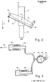
- Fig. 1, 1 denotes the frame of an X-ray examination apparatus which is mounted on the base 2 so as to be pivotable about a horizontal axis.
- a longitudinal carriage 3 can be moved within the frame 1 in its longitudinal direction.
- the longitudinal carriage 3 carries a transverse carriage 4 which can be moved on the longitudinal carriage transversely to the longitudinal direction of the device, ie in the direction of the arrow 5.
- On the cross carriage 4 is an X-ray tube, not shown, on the one hand and on the other hand, an X-ray target device 6 is arranged, which can be moved in the direction of arrow 7, ie perpendicular to the longitudinal and transverse directions - in the so-called compression direction.
- the weight of the longitudinal carriage together with the components carried by it is compensated for with the aid of a main counterweight 8 which can be moved in the longitudinal direction in the frame 1 and which is connected to the longitudinal carriage by means of ropes which are guided over rollers.
- the x-ray target device is coupled to a cylinder 9a, which, together with a piston 10a attached to the transverse carriage 4, encloses a volume of liquid.
- a compression counterweight 12 is coupled in the foot of the device to a cylinder 9b, which together with a piston 10b encloses a liquid volume which communicates with the liquid in the piston 10a and in the cylinder 9a via a hydraulic line in the form of a hose 11.
- the product of the weight 12 and the stroke of this counterweight is equal to the product of the weight of the target device 6 and the stroke of the target device.
- the target device 6 or the counterweight 12 is not coupled directly to the associated cylinder 9a or 9b, but via a lever arrangement in FIG Form of a parallelogram linkage which surrounds the cylinder 10 on two sides, one of which is shown in more detail in FIG. 3.
- the parallelogram linkage comprises a lever 13 which is articulated in the middle at 14 on the cylinder 9 and is articulated at one end to the end of a rod 15 and at the other end to the center of a rod 16.
- a rod 17 is articulated, which has the same length as the lever 13 and the other end of which is articulated to one end of the rod 16 such that the lever 13 and the rods 15, 16 and 17 form a parallelogram form.
- the free end of the rod 16 is articulated at a fixed point on the cross carriage 4 or in the frame 1, in such a way that this articulation point, the point 14 and the point of articulation between the rods 15 and 17 lie in one plane.
- the load i.e.
- the parallelogram linkage causes the cylinder 9 to experience half the stroke when the load is displaced relative to the fixed piston 10, like the load. As already mentioned, this allows the overall length of the cylinder 9-piston 10 system to be kept small.
- the described configuration of the parallelogram linkage also ensures that the articulation point 14 on the cylinder and the point at which the load is articulated always move on parallel (vertical in FIG. 3) straight lines which run in the direction of compression (arrow 7).
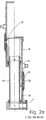
- the structure of a system consisting of cylinder and piston is shown in more detail in FIG. 2a, the system being shown on the right of the center line in a fully compressed state and on the left of the center line in a fully expanded state.
- the piston 10 consists of a Tube, which is provided at its lower end with a connection for the hose 11 (Fig. 1).
- the cylinder 9, which surrounds the piston 10, is closed at its upper end by an end face. Its inside diameter (eg 62 mm) is significantly larger than the outside diameter of the piston 10 (eg 46 mm), so that a relatively large space remains between the piston and the cylinder. This is sealed with the aid of a double-sided roller membrane 18 which surrounds the piston 10.
- the center of this rolling diaphragm is connected to the piston at 19 over the entire circumference.
- Their ends are connected by means of a press ring 20 to the lower end of the cylinder 9 and to a cylinder part 21, which serves only as a guide element and whose inside and outside diameters correspond to the corresponding dimensions of the cylinder 9.
- the two-sided roller membrane 18 thus seals on the one hand the space between the cylinder 9 and the piston 10 and on the other hand delimits a preferably liquid medium, for example glycerol.
- the pressure in this liquid is greater than the pressure in the liquid used for power transmission, the volume of which is limited by the cylinder 9 including its end face on one side of the roller membrane 18 and the piston 10.
- the roller membrane swells outwards and rolls on the inner surfaces and on the outer surface of the piston without wrinkles when the cylinder is displaced.
- the pressure inside the roller membrane also ensures that the cylinder 9 is aligned coaxially with the piston 10.
- the rolling diaphragm would form sharp folds on its side facing this fluid, which would practically block a displacement between the piston and the cylinder.
- the rolling membrane the elasticity of which should be as low as possible at least in the axial direction, can consist of a fabric of threads running in the axial direction, which is sealed on both sides by a rubber skin.
- the flex losses are also determined by the diameter of the inner surface of the cylinder on the one hand and the outer surface of the piston on the other. The greater the difference in diameter, the larger the diameter of the carded fold of the roll membrane and the smaller the flex losses.
- the load on the fabric increases with the size of the annular surface between the piston and the cylinder, so that thicker roller membranes may be required for larger diameter differences.
- the internal pressure in the rolling membrane must be greater than the pressure in the fluid for power transmission. This increased internal pressure can be maintained by hermetically sealing the inside of the rolling membrane from the outside. However, undesirable pressure fluctuations can still occur due to thermal expansion and the low flexibility of the roller membrane. However, these pressure fluctuations can be avoided if the inside of the rolling membrane is connected to a pressure accumulator via an opening 22 provided in the press ring 20. This pressure accumulator is shown schematically in Fig. 2b.
- It consists of a metal vessel 23, which is divided by an elastic membrane 24 into two chambers, of which the chamber 25 is filled with the liquid also in the rolling membrane and via the Outlet 22 communicates with it, while the second chamber, which is hermetically sealed to the outside, contains a pressurized gas, for example nitrogen.
- a pressurized gas for example nitrogen.
- the flex losses are the greater, the greater the pressure difference between the liquid in the rolling membrane and the atmospheric pressure on the one hand or the pressure in the liquid used for power transmission on the other.
- the greatest flexing losses therefore arise in an embodiment with constant pressure in the roll membrane when the table of the X-ray examination apparatus is vertical, because then the pressure in the fluid used for the power transmission is practically zero, so that there is a large pressure difference.
- This disadvantage can be avoided if, instead of a constant (maximum) pressure-generating accumulator, there is a pressure generator that only ever delivers the pressure difference required to maintain the tension of the roller membrane.
- This pressure generator shown in Fig. 2c consists of a vessel 28, which in turn is divided into two parts by a membrane 29, each of which has an outlet 30 and 31, respectively.
- the outlet 31 is connected to the outlet 22 and the outlet 30 to an outlet 32 in the vicinity of the end face of the cylinder 10 by means of a hose, not shown in each case.
- a compression spring 33 is additionally provided, which exerts a pressure on part of the membrane surface. Without this spring, this membrane would always be in such a position that the pressure inside the rolling membrane would be equal to the pressure in the fluid used for power transmission.
- the spring 33 By means of the spring 33, however, the pressure on the chamber provided with the outlet 31 is increased, so that the pressure in the rolling diaphragm is increased by a predetermined one, by the spring force dependent value is greater than the pressure in the fluid used for power transmission.
- the diaphragm 29 In the event of a leak in the roller diaphragm, the diaphragm 29 would be pushed all the way to the right by the spring force. If a suitable switch is placed there, e.g. a reed contact, which is actuated by a magnet on the membrane pushed into the extreme position, can generate an alarm signal.
- a suitable switch e.g. a reed contact, which is actuated by a magnet on the membrane pushed into the extreme position, can generate an alarm signal.
- the pressure in the fluid used for power transmission disappears when the X-ray examination device is pivoted into its vertical position. If the X-ray target device is pulled with little effort in this position, the counterweight can follow this movement. However, if the force acting on the target device 6 exceeds a critical value which corresponds to the product of the atmospheric pressure and the effective piston area, a vacuum or a vacuum is created, so that vapor is formed in the liquid; the counterweight then does not move as quickly as the target device, but follows with a delay and causes an annoyingly noticeable blow when the vapor bubble collapses.
- the desired function of the counterweight is only to support the x-ray target device 6 in the direction 7a (upward).
- a force effect. against this direction is not necessary and its elimination is even an advantage when operating the device vertically, because when the x-ray target device is moved in direction 7, the counterweight 12, once it has moved into its end position, does not participate in the movement and therefore also requires no acceleration forces to be applied by the operator.
- This decoupling in one direction is shown in FIG. 4, which on the one hand achieves the mentioned operating advantage and on the other hand eliminates the blow after vacuum formation mentioned above.
- the hose 11 is connected to an elastic bladder 34, which is located inside a rigid housing 35, which is provided with an opening or with a valve arrangement 36, so that air can flow into the housing and - possibly damped - out of the housing can.
- a force is now exerted in the direction of the arrow 37 or 7a, ie a tensile force on the target device 6 or the cylinder 9a connected to it, the cylinder 9a follows this force, with the increasing volume in the system 9a, 10a resulting from the liquid flowing after the elastic bubble 34 is filled.
- the cylinder 9b does not move relative to the cylinder 10b, ie the counterweight is then no longer coupled to the movements of the target device, which, as mentioned, has the advantage that in this position the user only has to move the mass of the target device.
- Cylinder-piston systems have identical dimensions. With different dimensions of the two systems, different transmission ratios can be achieved (that is, when the cylinder 9a is displaced, the cylinder 9b does not move the same distance), which can be used, if necessary, to counterbalance the weight with smaller counterweights or with smaller cylinder strokes to reach.
- the cylinder surround the piston. Rather, the cylinder could be arranged inside the tubular piston and connected to the piston via a rolling membrane.
- two pistons preferably of different diameters, could also be immersed in opposite directions from one cylinder so that they can penetrate one another.
- the pistons would then have to be closed on both sides by an end face and the cylinder diameter would have to be adjusted in the axial direction so that the center between the inner wall of the cylinder and the outer wall of the piston has the same distance from the cylinder axis.
- a system with more than two collapsible parts with stepped diameters could also be used, between each of which a roller membrane would be arranged. These parts would then be pushed apart or pushed together telescopically during a displacement, with a suitable synchronous selection making it possible to achieve a uniform, synchronous displacement of all the telescopic parts.
Landscapes
- Health & Medical Sciences (AREA)
- Life Sciences & Earth Sciences (AREA)
- Medical Informatics (AREA)
- Engineering & Computer Science (AREA)
- Radiology & Medical Imaging (AREA)
- Molecular Biology (AREA)
- Biophysics (AREA)
- Nuclear Medicine, Radiotherapy & Molecular Imaging (AREA)
- Optics & Photonics (AREA)
- Pathology (AREA)
- Physics & Mathematics (AREA)
- Biomedical Technology (AREA)
- Heart & Thoracic Surgery (AREA)
- High Energy & Nuclear Physics (AREA)
- Surgery (AREA)
- Animal Behavior & Ethology (AREA)
- General Health & Medical Sciences (AREA)
- Public Health (AREA)
- Veterinary Medicine (AREA)
- Actuator (AREA)
- Apparatus For Radiation Diagnosis (AREA)
Abstract
Bei dem Röntgengerät nach der Erfindung erfolgt ein Gegengewichtsausgleich hydraulisch mit Hilfe zweier Zylinder-Kolben-Systeme, die über eine hydraulische Verbindung miteinander in Verbindung stehen und von denen das eine mit dem zu verschiebenden Geräteteil, beispielsweise einem Röntgenzielgerät, und das andere mit einem Gegengewicht gekoppelt ist. Bei einer Verschiebung des Geräteteils wird das Gegengewicht in der entgegengesetzten Richtung bewegt, so daß bei der Bewegung des Geräteteils lediglich Beschleunigungs- und Reibungskräfte aufzubringen sind Vorzugsweise befindet sich zwischen Kolben und Zylinder ein ringförmiger Zwischenraum, in dem eine flexible Rollmembran, die sowohl am Kolben als auch am Zylinder eingespannt ist, die Abdichtung nach außen bewirkt.In the X-ray device according to the invention, a counterbalance is carried out hydraulically with the aid of two cylinder-piston systems which are connected to one another via a hydraulic connection and of which one is coupled to the part of the device to be moved, for example an X-ray target device, and the other is coupled to a counterweight is. When the part of the device is moved, the counterweight is moved in the opposite direction, so that only acceleration and frictional forces are to be applied when the part of the device is moved.There is preferably an annular space between the piston and cylinder, in which a flexible roller membrane, both on the piston and is also clamped on the cylinder, causing the seal to the outside.
Description
Die Erfindung betrifft ein Röntgengerät mit einem daran verfahrbaren Geräteteil und einem damit hydraulisch gekoppelten, gegensinnig zu dem Geräteteil bewegbaren Gegengewicht sowie mit einer der hydraulischen Kraftübertragung dienenden Zylinderanordnung.The invention relates to an X-ray device with a device part that can be moved thereon and a counterweight that is hydraulically coupled to it and that can be moved in the opposite direction to the device part, and with a cylinder arrangement that serves to transmit hydraulic power.
Ein solches Röntgengerät ist aus dem DE-GM 172 886 bekannt. Dabei ist das Gegengewicht mit dem Kolben und das Geräteteil - ein Röntgenzielgerät - mit dem Zylinder verbunden. Der Kolben unterteilt den Zylinder in zwei Teile, die über Leitungen mit einer Flüssigkeitspumpe oder dergleichen verbunden sind, so daß Flüssigkeit von dem einen Teil des Kolbens in den anderen gepumpt werden kann, was zur Folge hat, daß der Kolben im Innern des Zylinders bzw. das Röntgenzielgerät verschoben wird. Das Röntgenzielgerät wird im Ruhezustand, d.h. wenn keine Kraft darauf einwirkt, von dem Gegengewicht in seiner Lage gehalten. Wenn eine Kraft auf das Zielgerät einwirkt, bewegen sich zunächst das Gegengewicht und das Zielgerät gegensinnig zueinander, so daß der Benutzer in diesem Stadium Arbeit lediglich zur Überwindung der Beschleunigungs- und Reibungskräfte zu leisten hat. Sobald aber das Gegengewicht um eine bestimmte Strecke aus seiner Ruhelage ausgelenkt ist, wird ein Schieber geöffnet, der die Pumpe in der gewünschten Weise mit den beiden durch den Kolben voneinander getrennten Zylinderteilen verbindet, und das Röntgenzielgerät wird durch den Pumpendruck verschoben. Da sich nach Abschluß dieses Vorganges das Gegengewicht wieder in seiner Ausgangslage befindet, muß die Arbeit, d.h. beispielsweise das Anheben des Röntgenzielgerätes, durch die Pumpe geleistet werden. Bei einem Defekt der Pumpe oder der Pumpensteuerung ist eine Verschiebung des Röntgenzielgerätes praktisch nicht möglich.Such an X-ray device is known from DE-GM 172 886. The counterweight is connected to the piston and the device part - an X-ray target device - to the cylinder. The piston divides the cylinder into two parts, which are connected via lines to a liquid pump or the like, so that liquid can be pumped from one part of the piston to the other, with the result that the piston inside the cylinder or the x-ray target device is moved. The x-ray target device is held in its position by the counterweight in the idle state, ie when no force acts on it. When a force acts on the target device, the counterweight and the target device first move in opposite directions to one another, so that the user only has to do work at this stage to overcome the acceleration and friction forces. However, as soon as the counterweight is deflected from its rest position by a certain distance, a slide is opened which connects the pump in the desired manner to the two cylinder parts separated by the piston, and the X-ray target device is displaced by the pump pressure. Since after this process the counterweight is back in its starting position, the work, ie for example lifting the X-ray target device, be done by the pump. If the pump or the pump control is defective, it is practically impossible to move the X-ray target device.
Auf der anderen Seite sind zwar auch Röntgengeräte bekannt, bei denen das Geräteteil durch den Benutzer von Hand bewegt werden kann (DBP 23 24 699), weil das Gegengewicht dabei stets gegensinnig zum Röntgenzielgerät bewegt wird. Die Kraftübertragung erfolgt dabei mit Hilfe von Seilen, die über eine Anzahl von Rollen geführt sind. Die Kräfte, die zur Überwindung der Reibung in den Seilen erforderlich sind, können bei einem großen Gewicht des Geräteteils jedoch unzumutbar hohe Werte erreichen.On the other hand, X-ray devices are also known in which the device part can be moved by the user by hand (DBP 23 24 699) because the counterweight is always moved in the opposite direction to the X-ray target device. The power transmission takes place with the help of ropes that are guided over a number of rollers. However, the forces required to overcome the friction in the ropes can reach unreasonably high values if the device part is heavy.
Aufgabe der vorliegenden Erfindung ist es, ein Gerät der eingangs genannten Art so auszugestalten, daß die Verschiebung ohne Pumpe allein von Hand erfolgen kann.The object of the present invention is to design a device of the type mentioned at the outset in such a way that the displacement can be carried out by hand without a pump.
Diese Aufgabe wird erfindungsgemäß dadurch gelöst, daß sowohl dem Geräteteil als auch dem Gegengewicht je ein Zylinder und ein Kolben zugeordnet sind, von denen der eine Teil fest und der andere Teil mit dem Geräteteil bzw. dem Gegengewicht verbunden ist, und daß der von einem Kolben und einem Zylinder umschlossene Flüssigkeitsraum über eine hydraulische Verbindung mit dem entsprechenden von dem anderen Zylinder und dem anderen Kolben umschlossenen Raum verbunden ist.This object is achieved in that both the device part and the counterweight are each assigned a cylinder and a piston, of which one part is fixed and the other part is connected to the device part or the counterweight, and that of a piston and a cylinder-enclosed liquid space is connected via a hydraulic connection to the corresponding space enclosed by the other cylinder and the other piston.
Bei der Erfindung ist der Geräteteil also mit einem der Zylinder oder einem der Kolben gekoppelt; das gleiche gilt für das Gegengewicht. Wenn das Geräteteil bewegt wird, ändert sich das von dem zugehörigen Zylinder und dem zugehörigen Kolben umschlossene Volumen. Diese Volumenänderung erzwingt in dem anderen System aus Zylinder und Kolben eine qleich große aber entgegengesetzte Volumenänderung. Wird beispielsweise in dem einen System das Volumen größer, dann wird es in dem anderen System im gleichen Maße kleiner. Durch diese gegensinnige Änderung der von den Zylindern und den Kolben umschlossenen Flüssigkeitsvolumina läßt sich eine gegensinnige Bewegung von Geräteteil und Gegengewicht erreichen.In the invention, the device part is thus coupled to one of the cylinders or one of the pistons; the same applies to the counterweight. When the device part is moved, the volume enclosed by the associated cylinder and the associated piston changes. This change in volume forces an equal but opposite change in volume in the other cylinder and piston system. If, for example, the volume becomes larger in one system, it becomes smaller in the other system to the same extent. This change in the opposite direction of the liquid volumes enclosed by the cylinders and the pistons enables the device part and counterweight to move in opposite directions.
Der Begriff "Kolben" ist im Zusammenhang mit der Erfindung weit zu interpretieren. Es ist nicht erforderlich, daß der Kolben wie bei der bekannten Einrichtung den Zylinder in zwei Teilräume unterteilt; vielmehr kann der Kolben auch die Form eines Rohres haben. Wesentlich ist nur, daß der Kolben und der Zylinder zusammen ein Flüssigkeitsvolumen nach außen hin abschließen, wenn man einmal von der darin enthaltenen Öffnung für die hydraulische Verbindung zwischen den beiden aus Zylinder und Kolben bestehenden Systemen absieht.The term "piston" is to be interpreted broadly in connection with the invention. It is not necessary for the piston, as in the known device, to divide the cylinder into two subspaces; rather, the piston can also have the shape of a tube. It is only important that the piston and the cylinder together close off a volume of liquid to the outside, apart from the opening contained therein for the hydraulic connection between the two systems consisting of cylinder and piston.
Da Kolben und Zylinder leicht gegeneinander verschiebbar sein, andererseits aber das Flüssigkeitsvolumen nach außen hin dicht abschließen müssen, ist eine entsprechende Dichtung erforderlich. Eine extrem genaue Abstimmung der Durchmesser aufeinander könnte zwar eine leicht verschiebbare Dichtung bilden, bedingte jedoch einen hohen Fertigungsaufwand und wäre empfindlich gegen feinste körnige Verunreinigungen. Zudem wäre ein geringer Flüssigkeitsdurchtritt unvermeidlich. Ein solcher Flüssigkeitsaustritt kann bekanntlich auch bei weniger genauer Abstimmung der Durchmesser fast völlig vermieden werden durch Einfügen von elastischen Dichtungsringen oder Dichtungsmanschetten. Diese jedoch bewirken durch ihren Anpreßdruck Reibung, die für den hier verfolgten Einsatzzweck zu hohe Werte annimmt (ca. 6 bis 10 % der Nutzkraft je Zylinder).Since the piston and cylinder can be easily moved against one another, but on the other hand must seal off the liquid volume tightly from the outside, a corresponding seal is required. An extremely precise matching of the diameters to one another could form an easily displaceable seal, but it required a lot of production and would be sensitive to the finest granular contaminants. In addition, a low liquid penetration would be inevitable. Such a leakage of liquid can, as is known, be almost completely avoided even with less precise adjustment of the diameters by inserting elastic sealing rings or sealing sleeves. However, due to their contact pressure, these cause friction which takes on values that are too high for the purpose pursued here (approx. 6 to 10% of the useful force per cylinder).
Diese Nachteile lassen sich nach einer Weiterbildung der Erfindung dadurch vermeiden, daß der Außendurchmesser jedes der beiden Kolben (bzw. Zylinder) deutlich kleiner ist als der Innendurchmesser der Zylinder (bzw. Kolben) und daß der Zwischenraum zwischen diesen beiden Teilen durch eine Rollmembran abgedichtet ist, die unter einer Spannung steht.According to a development of the invention, these disadvantages can be avoided by the fact that the outside diameter of each of the two pistons (or cylinders) is significantly smaller than the inside diameter of the cylinders (or pistons) and that the intermediate space between these two parts is sealed by a roller membrane that is under tension.
Bei Rollmembranen wird der äußere Rand am Zylinder eingespannt und durch einen gegenüber dem Zylinder wesentlich kleineren Kolben der Boden der Membran in den übrigen Teil durchgestülpt. Dabei legt sich der annähernd zylindrische Mantel der Membran in dem durchgestülpten Teil an den Kolben, im übrigen Teil an den Zylinder an. Der Zwischenraum wird durch eine sich beim Bewegen abrollende Falte überbrückt. Diese Rollmembranen haben wegen ihrer Herstellung aus ebenem Gewebe eine auf den Durchmesser bezogen beschränkte Höhe und deshalb einen vom Durchmesser abhängigen Hub (Höhe nicht größer als Durchmesser).In the case of rolling diaphragms, the outer edge is clamped on the cylinder and the bottom of the diaphragm is pushed into the remaining part by means of a piston which is considerably smaller than the cylinder. The approximately cylindrical mantle of the membrane lies against the piston in the slipped part, and against the cylinder in the remaining part. The gap is bridged by a fold that rolls off when moving. Because of their manufacture from flat fabric, these roll membranes have a height that is limited by diameter and therefore have a stroke that is dependent on the diameter (height not greater than diameter).
Diese Einschränkung wird vermieden, wenn die Membran in rohrförmiger Gestalt mit einer im wesentlichen nur axial oder unter einem spitzen Winkel zur Achse verlaufenden Fadenlage hergestellt wird. Dadurch ist die Elastizität in Umfangsrichtung wesentlich größer als in Längsrichtung. Eine solche Membran wird sich bei Einwirkung einer Druckspannung durch ein fließfähiges Medium von der Innenseite der durchgestülpten Falte her einerseits an den Kolben und andererseits an den Zylinder anlegen, ohne in Längsrichtung auszuweichen. Die Druckspannung bewirkt außerdem, daß beim relativen Verschieben von Kolben und Zylinder die Membran keine die Bewegung behindernden Querfalten bildet.This restriction when the membrane adenlage in a tubular shape with a substantially extends only axially or at an acute angle to the axis F is produced is avoided. As a result, the elasticity in the circumferential direction is significantly greater than in the longitudinal direction. When a compressive stress is applied by a flowable medium, such a membrane will contact the piston and the cylinder on the one hand from the inside of the folded fold, without deviating in the longitudinal direction. The compressive stress also has the effect that when the piston and cylinder are displaced relative to one another, the membrane does not form any transverse folds which hinder the movement.
Die Spannung der Membran könnte durch den Flüssigkeitsdruck der zur Kraftübertragung dienenden Flüssigkeit erzeugt werden. Dies setzt allerdings voraus, daß die Flüssigkeit immer unter Druck steht. Bei einem um eine horizontale Achse schwenkbaren Röntgenuntersuchungsgerät, dessen Röntgenzielgerät für die Kompressionsbewegung mit einem derartigen Gewichtsausgleich versehen ist, ist diese Voraussetzung jedoch dann nicht erfüllt, wenn das Röntgenuntersuchungsgerät senkrecht steht, so daß die Kompressionsrichtung waagerecht verläuft. In diesem Fall könnte eine Vorspannung der Rollenmembranen der beiden Zylinder-Kolben-Systeme dadurch erzeugt werden, daß sowohl das Geräteteil (Röntgenzielgerät) als auch das Gegengewicht unter der Einwirkung von gleich großen, einander aufhebenden Kräften, die beispielweise mittels einer Federanordnung erzeugt und ggf. von einem dünnen Seil übertragen werden könnten, stehen.The tension of the membrane could be caused by the fluid pressure of the fluid used for power transmission be generated. However, this presupposes that the liquid is always under pressure. In the case of an X-ray examination device which can be pivoted about a horizontal axis and whose X-ray target device for the compression movement is provided with such a weight compensation, this requirement is not met, however, if the X-ray examination device is vertical, so that the compression direction runs horizontally. In this case, a prestressing of the roller membranes of the two cylinder-piston systems could be generated in that both the device part (X-ray target device) and the counterweight under the action of equally large, mutually canceling forces, which are generated, for example, by means of a spring arrangement and possibly could be transmitted by a thin rope.
Statt dessen sieht eine bevorzugte Weiterbildung der Erfindung vor, daß die Rollenmembran zweiseitig ausgebildet und mit einem flüssigen oder gasförmigen Medium gefüllt ist, dessen Innendruck größer ist als der Druck in dem der Kraftübertragung dienenden Flüssigkeitsvolumen. Hier wird die Vorspannung der zweiseitig ausgebildeten Rollenmembran also durch den erhöhten Druck in dem darin enthaltenen Medium erzeugt. Im allgemeinen ist ein flüssiges Medium einem gasförmigen Medium vorzuziehen, weil es damit weniger Diffusionsverluste gibt. Auch hierbei ist ein konstanter Druck, d.h. eine konstante Spannung der Rollenmembran, nicht unter allen Umständen aufrechtzuerhalten; eine Erwärmung der in der Rollmembran enthaltenen Flüssigkeit könnte infolge ihres thermischen Ausdehnungskoeffizienten zu einer Erhöhung des Druckes führen. Dies läßt sich jedoch nach einer Weiterbildung der Erfindung dadurch vermeiden, daß das Medium mit einem Speicher gekoppelt ist, der durch eine Membran abgeschlossen ist und unter Druck stehendes Gas enthält.Instead, a preferred development of the invention provides that the roller membrane is formed on two sides and is filled with a liquid or gaseous medium, the internal pressure of which is greater than the pressure in the liquid volume used for power transmission. Here, the preload of the double-sided roller membrane is generated by the increased pressure in the medium it contains. In general, a liquid medium is preferable to a gaseous medium because there is less diffusion loss. Here too there is a constant pressure, i.e. a constant tension of the roller membrane not to be maintained under all circumstances; A heating of the liquid contained in the rolling membrane could lead to an increase in pressure due to its coefficient of thermal expansion. However, according to a further development of the invention, this can be avoided in that the medium is coupled to a memory which is closed off by a membrane and contains gas under pressure.
Die Kräfte, die der Benutzer bei einem derart ausgebildeten Röntgengerät aufbringen muß, hängen von der Differenz des Druckes in der Rollenmembran einerseits und in der der Kraftübertragung dienenden Flüssigkeit andererseits ab. Je größer diese Differenz ist, desto mehr Kräfte muß der Benutzer zur Verschiebung des Geräteteils aufbringen. Da bei einem um eine horizontale umlegbaren Röntgenuntersuchungsgerät der Druck in der der Kraftübertragung dienenden Flüssigkeit wie bereits erläutert von der Neigung des Röntgenuntersuchungsgerätes abhängt, ist - bei konstantem Druck in dem Druckspeicher - auch die Druckdifferenz bzw. die vom Benutzer zur Verschiebung des Geräteteils aufzubringende Kraft von der jeweiligen Neigung abhängig.The forces that the user must exert in the case of an X-ray device designed in this way depend on the difference in the pressure in the roller membrane on the one hand and in the liquid used for power transmission on the other. The greater this difference, the more forces the user has to apply to move the device part. Since the pressure in the power transmission fluid depends on the inclination of the X-ray examination device in the case of a X-ray examination device which can be folded around a horizontal axis, the pressure difference or the force to be applied by the user to move the device part is also - with constant pressure in the pressure accumulator depending on the respective inclination.
Diese Abhängigkeit läßt sich nach einer Weiterbildung der Erfindung dadurch vermeiden, daß ein durch eine Membran unterteilter Behälter vorgesehen ist, dessen eines Teilvolumen mit der der Kraftübertragung dienenden Flüssigkeit und dessen anderes Teilvolumen mit dem Medium im Innern der Rollenmembran in Verbindung steht, und daß Mittel zur Ausübung einer zusätzlichen Kraft auf die Membran vorgesehen sind derart, daß der Druck in dem Medium in der Rollmembran größer ist als der Druck in der der Kraftübertragung dienenden Flüssigkeit. Bei dieser Ausführung wird die Druckdifferenz allein durch die zusätzliche z.B. mittels einer Feder aufgebrachte Kraft auf die Membran hervorgerufen. Durch geeignete Bemessung dieser Kraft läßt sich daher der zum Bewegen des Geräteteils erforderliche Kraftaufwand für den Benutzer besonders klein halten.According to a development of the invention, this dependency can be avoided by providing a container divided by a membrane, one part of which is connected to the liquid used for power transmission and the other part of which is connected to the medium inside the roller membrane, and by means for An additional force is exerted on the membrane in such a way that the pressure in the medium in the rolling membrane is greater than the pressure in the liquid used to transmit the force. In this version, the pressure difference is determined solely by the additional e.g. force applied to the membrane by means of a spring. By suitably dimensioning this force, the effort required for moving the device part can therefore be kept particularly small for the user.
Um mit einem Gewichtsausgleich eine bestimmte Verschiebung zwischen Zylinder und Kolben zu erreichen, muß das System Zylinder - Kolben in expandiertem Zustand eine Länge aufweisen, die dem rund 2,5-fachen dieser Verschiebung entspricht. Um nun einerseits die Länge des Systems Zylinder - Kolben nicht zu groß werden zu lassen und andererseits eine ausreichenden Verschiebeweg für das Geräteteil zu erreichen, sieht eine Weiterbildung der Erfindung vor, daß das Geräteteil und/oder das Gegengewicht mit dem zugehörigen Zylinder (Kolben) über eine Hebelanordnung verbunden sind, die so ausgebildet ist, daß bei einer Verschiebung des Geräteteils bzw. des Gegengewichtes der damit gekoppelte Zylinder (Kolben) in geringerem Maße verschoben wird.In order to achieve a certain displacement between the cylinder and piston with a weight balance, the cylinder-piston system must have a length in the expanded state point that corresponds to around 2.5 times this shift. In order not to let the length of the cylinder-piston system become too long on the one hand and on the other hand to achieve a sufficient displacement path for the device part, a further development of the invention provides that the device part and / or the counterweight with the associated cylinder (piston) a lever arrangement is connected, which is designed such that when the device part or the counterweight is displaced, the cylinder (piston) coupled therewith is displaced to a lesser extent.
Die Erfindung wird nachstehend anhand der Zeichnung näher erläutert. Es zeigen
- Fig. 1 ein Ausführungsbeispiel,
- Fig. 2a einen Querschnitt durch ein Zylinder-Kolben-System,
- Fig. 2b die Erzeugung eines konstanten Innendruckes in der Rollenmembran,
- Fig. 2c die Erzeugung einer konstanten Druckdifferenz,
- Fig. 3 ein Parallelogrammgestänge zur Umsetzung der Bewegung in eine verringerte Zylinderverschiebung, und
- Fig. 4 eine weitere Ausgestaltung des Gerätes nach Fig. 1.
- 1 shows an embodiment,
- 2a shows a cross section through a cylinder-piston system,
- 2b the generation of a constant internal pressure in the roller membrane,
- 2c the generation of a constant pressure difference,
- Fig. 3 is a parallelogram linkage to implement the movement in a reduced cylinder displacement, and
- 4 shows a further embodiment of the device according to FIG. 1.
In Fig. 1 ist mit 1 der Rahmen eines Röntgenuntersuchungsgerätes bezeichnet, das an dem Fuß 2 um eine horizontale Achse schwenkbar gelagert ist. Ein Längswagen 3 kann innerhalb des Rahmens 1 in dessen Längsrichtung verschoben werden. Der Längswagen 3 trägt einen Querwagen 4, der auf dem Längswagen quer zur Längsrichtung des Gerätes, d.h. in Richtung des Pfeiles 5, verfahrbar ist. An dem Querwagen 4 ist einerseits eine nicht näher dargestellte Röntgenröhre und andererseits ein Röntgenzielgerät 6 angeordnet, das in Richtung des Pfeiles 7, d.h. senkrecht zu der Längs- und Querrichtung - in der sogenannten Kompressionsrichtung - verfahrbar ist.In Fig. 1, 1 denotes the frame of an X-ray examination apparatus which is mounted on the
Das Gewicht des Längswagens mitsamt der von ihm getragenen Bauteile wird mit Hilfe eines in dem Rahmen 1 in dessen Längsrichtung verfahrbaren Hauptgegengewichtes 8 ausgeglichen, das mit dem Längswagen über Seile verbunden ist, die über Rollen geführt sind.The weight of the longitudinal carriage together with the components carried by it is compensated for with the aid of a main counterweight 8 which can be moved in the longitudinal direction in the
Zum Gewichtsausgleich in Kompressionsrichtung ist das Röntgenzielgerät mit einem Zylinder 9a gekoppelt, der zusammen mit einem an dem Querwagen 4 befestigten Kolben 10a ein Flüssigkeitsvolumen umschließt. Ebenso ist im Fuß des Gerätes ein Kompressionsgegengewicht 12 mit einem Zylinder 9b gekoppelt, der zusammen mit einem Kolben 10b ein Flüssigkeitsvolumen umschließt, das über eine hydraulische Leitung in Form eines Schlauches 11 mit der Flüssigkeit in dem Kolben 10a und im Zylinder 9a kommuniziert. Wenn das Zielgerät 6 in Kompressionsrichtung (Pfeil 7) auf den Rahmen 1 zubewegt wird, senkt sich der Zylinder 9a und das dadurch verdrängte Flüssigkeitsvolumen' hebt den Zylinder 9b mit dem damit gekoppelten Gegengewicht 12. Das Produkt aus dem Gewicht 12 und dem Hub dieses Gegengewichtes ist gleich dem Produkt aus dem Gewicht des Zielgerätes 6 und dem Hub des Zielgerätes. Daher besteht ein Gewichtsausgleich: Das Röntgenzielgerät 6 wird durch das Gegengewicht in seiner jeweiligen Position gehalten, und zur Verschiebung des Röntgenzielgerätes muß der Benutzer lediglich Beschleunigungskräfte aufbringen und die Reibung überwinden.For weight compensation in the compression direction, the x-ray target device is coupled to a
Wie aus Fig. 1 hervorgeht, ist das Zielgerät 6 bzw. das Gegengewicht 12 nicht direkt mit dem zugehörigen Zylinder 9a bzw. 9b gekoppelt, sondern über eine Hebelanordnung in Form eines Parallelogrammgestänges, das den Zylinder 10 auf zwei Seiten umgreift, von denen das eine in Fig. 3 näher dargestellt ist.As can be seen from FIG. 1, the target device 6 or the
Das Parallelogrammgestänge umfaßt einen Hebel 13, der in seiner Mitte bei 14 am Zylinder 9 angelenkt ist und an seinem einen Ende mit dem Ende einer Stange 15 und mit seinem anderen Ende mit der Mitte einer Stange 16 gelenkig verbunden ist. An das andere Ende der Stange 15 ist eine Stange 17 angelenkt, die die gleiche Länge hat wie der Hebel 13 und deren anderes Ende an ein Ende der Stange 16 angelenkt ist derart, daß der Hebel 13 und die Stangen 15, 16 und 17 ein Parallelogramm bilden. Das freie Ende der Stange 16 ist an einem festen Punkt am Querwagen 4 bzw. im Rahmen 1 angelenkt, und zwar so, daß dieser Anlenkpunkt, der Punkt 14 und der Gelenkpunkt zwischen den Stangen 15 und 17 in einer Ebene liegen. An dem Gelenkpunkt der Stangen 15 und 17 ist die Last, d.h. das Zielgerät 6, bzw. das Gegengewicht 12 befestigt. Das Parallelogrammgestänge bewirkt, daß bei einer Verschiebung der Last der Zylinder 9 gegenüber dem feststehenden Kolben 10 den halben Hub,erfährt wie die Last. Dadurch kann wie bereits erwähnt die Baulänge des Systems Zylinder 9 - Kolben 10 klein gehalten werden. Durch die beschriebene Ausbildung des Parallelogrammgestänges wird überdies erreicht, daß sich der Gelenkpunkt 14 am Zylinder und der Punkt, an dem die Last angelenkt ist, immer auf parallelen (in Fig. 3 vertikalen) Geraden bewegen, die in Kompressionsrichtung (Pfeil 7) verlaufen.The parallelogram linkage comprises a
Der Aufbau eines aus Zylinder und Kolben bestehenden Systems ist in Fig. 2a näher dargestellt, wobei das System rechts von der Mittellinie in ganz zusammengedrücktem und links von der Mittellinie in ganz auseinandergezogenem Zustand dargestellt ist. Der Kolben 10 besteht aus einem Rohr, das an seinem unteren Ende mit einem Anschluß für den Schlauch 11 (Fig. 1) versehen ist. Der Zylinder 9, der den Kolben 10 umschließt, ist an seinem oberen Ende durch eine Stirnfläche abgeschlossen. Sein Innendurchmesser (z.B. 62 mm) ist deutlich größer als der Außendurchmesser des Kolbens 10 (z.B. 46 mm), so daß zwischen Kolben und Zylinder ein relativ großer Zwischenraum verbleibt. Dieser wird mit Hilfe einer zweiseitigen Rollmembran 18 abgedichtet, die den Kolben 10 umschließt. Die Mitte dieser Rollmembran ist bei 19 auf dem ganzen Umfang mit dem Kolben verbunden. Ihre Enden sind mit Hilfe eines Preßringes 20 mit dem unteren Ende des Zylinders 9 sowie mit einem Zylinderteil 21 verbunden, der nur als Führungselement dient und dessen Innen- und Außendurchmesser mit den entsprechenden Maßen des Zylinders 9 übereinstimmen. Die zweiseitige Rollenmembran 18 dichtet also einerseits den Zwischenraum zwischen dem Zylinder 9 und dem Kolben 10 ab und begrenzt andererseits ein vorzugsweise flüssiges Medium, z.B. Glycerin.The structure of a system consisting of cylinder and piston is shown in more detail in FIG. 2a, the system being shown on the right of the center line in a fully compressed state and on the left of the center line in a fully expanded state. The
Der Druck in dieser Flüssigkeit ist größer als der Druck in der der Kraftübertragung dienenden Flüssigkeit, deren Volumen durch den Zylinder 9 einschließlich seiner Stirnfläche die eine Seite der Rollmembran 18 und den Kolben 10 begrenzt wird. Infolgedessen bläht sich die Rollenmembran nach außen hin auf und wälzt sich bei einer Verschiebung des Zylinders auf dessen Innenflächen sowie auf der Außenfläche des Kolbens faltenfrei ab. Durch den Druck im Innern der Rollmembran wird außerdem erreicht, daß der Zylinder 9 koaxial zum Kolben 10 ausgerichtet wird.The pressure in this liquid is greater than the pressure in the liquid used for power transmission, the volume of which is limited by the
wäre der Innendruck in der Rollmembran kleiner als der Druck in der der Kraftübertragung dienenden Flüssigkeit, würde die Rollmembran auf ihrer dieser Flüssigkeit zugewandten Seite scharfe Falten bilden, die eine Verschiebung zwischen Kolben und Zylinder praktisch blockieren würden.if the internal pressure in the rolling diaphragm were less than the pressure in the fluid used for power transmission, the rolling diaphragm would form sharp folds on its side facing this fluid, which would practically block a displacement between the piston and the cylinder.
Die Rollmembran, deren Elastizität zumindest in axialer Richtung möglichst gering sein sollte, kann aus einem Gewebe von in axialer Richtung verlaufenden Fäden bestehen, das beidseitig durch eine Gummihaut abgedichtet ist. Je dünner die Rollmembran ist, desto geringer sind die bei einer Verschiebung des Zylinders auftretenden Walkverluste in der Membran und damit letztlich die vom Benutzer zur Bewegung des Zielgerätes aufzubringenden Kräfte. Die Walkverluste werden aber auch durch den Durchmesser der Innenfläche des Zylinders einerseits und der Außenfläche des Kolbens andererseits bestimmt. Je größer der Durchmesserunterschied ist, desto größer ist der Durchmesser der Krempelfalte der Rollmembran und desto kleiner sind die Walkverluste. Auf der anderen Seite steigt die Belastung des Gewebes mit der Größe der Kreisringfläche zwischen Kolben und Zylinder, so daß bei größeren Durchmesserunterschieden dickere Rollmembranen erforderlich sein können.The rolling membrane, the elasticity of which should be as low as possible at least in the axial direction, can consist of a fabric of threads running in the axial direction, which is sealed on both sides by a rubber skin. The thinner the rolling membrane, the lower the flexing losses in the membrane which occur when the cylinder is displaced, and thus ultimately the forces to be exerted by the user to move the target device. The flex losses are also determined by the diameter of the inner surface of the cylinder on the one hand and the outer surface of the piston on the other. The greater the difference in diameter, the larger the diameter of the carded fold of the roll membrane and the smaller the flex losses. On the other hand, the load on the fabric increases with the size of the annular surface between the piston and the cylinder, so that thicker roller membranes may be required for larger diameter differences.
Wie bereits erwähnt, muß der Innendruck in der Rollmembran größer sein als der Druck in der Flüssigkeit zur Kraftübertragung. Dieser erhöhte Innendruck kann dadurch aufrechterhalten werden, daß das Innere der Rollmembran hermetisch nach außen abgedichtet wird. Allerdings können sich auch dann noch aufgrund thermischer Ausdehnungungen und der geringen Nachgiebigkeit der Rollmembran unerwünschte Druckschwankungen ergeben. Diese Druckschwankungen können aber vermieden werden, wenn das Innere der Rollmembran über eine in dem Preßring 20 vorgesehene Öffnung 22 an einen Druckspeicher angeschlossen wird. Dieser Druckspeicher ist in Fig. 2bschematisch dargestellt. Er besteht aus einem Metallgefäß 23, das durch eine elastische Membran 24 in zwei Kammern unterteilt wird, von denen die Kammer 25 mit der auch in der Rollmembran befindlichen Flüssigkeit gefüllt ist und über den Auslaß 22 mit dieser in Verbindung steht, während die zweite nach außen hin hermetisch dichte Kammer ein unter Druck stehendes Gas z.B. Stickstoff enthält.As already mentioned, the internal pressure in the rolling membrane must be greater than the pressure in the fluid for power transmission. This increased internal pressure can be maintained by hermetically sealing the inside of the rolling membrane from the outside. However, undesirable pressure fluctuations can still occur due to thermal expansion and the low flexibility of the roller membrane. However, these pressure fluctuations can be avoided if the inside of the rolling membrane is connected to a pressure accumulator via an
Die Walkverluste sind um so größer, je größer der Druckunterschied zwischen der Flüssigkeit in der Rollmembran und dem Atmosphärendruck einerseits bzw. dem Druck in der der Kraftübertragung dienenden Flüssigkeit andererseits ist. Die größten Walkverluste ergeben sich daher bei einer Ausführungsform mit konstantem Druck in der Rollmembran, wenn der Tisch des Röntgenuntersuchungsgerätes senkrecht steht, weil dann der Druck in der der Kraftübertragung dienenden Flüssigkeit praktisch Null ist, so daß sich eine große Druckdifferenz ergibt. Dieser Nachteil läßt sich vermeiden, wenn anstatt eines ständig einen konstanten (maximalen) Druck erzeugenden Speichers ein Druckerzeuger tritt, der immer nur die zur Aufrechterhaltung der Spannung der Rollenmembran erforderliche Druckdifferenz liefert. Dieser in Fig. 2c dargestellte Druckerzeuger besteht aus einem Gefäß 28, das wiederum durch eine Membran 29 in zwei Teile unterteilt wird, von denen jeder einen Auslaß 30 bzw. 31 besitzt. Der Auslaß 31 ist mit dem Auslaß 22 und der Auslaß 30 mit einem Auslaß 32 in der Nähe der Stirnfläche des Zylinders 10 über je einen nicht näher dargestellten Schlauch verbunden. In der mit dem Auslaß 30 bzw. über eine nicht näher dargestellte Leitung mit dem Auslaß 32 im Zylinder 10 verbundenen Kammer ist zusätzlich eine Druckfeder 33 vorgesehen, die auf einen Teil der Membranfläche einen Druck ausübt. Ohne diese Feder würde diese Membran stets eine solche Lage einnehmen, daß der Druck im Innern der Rollmembran gleich dem Druck in der der Kraftübertragung dienenden Flüssigkeit wäre. Durch die Feder 33 jedoch wird der Druck auf die mit dem Auslaß 31 versehene Kammer erhöht, so daß der Druck in der Rollmembran um einen vorgegebenen, von der Federkraft abhängigen Wert größer ist als der Druck in der der Kraftübertragung dienenden Flüssigkeit.The flex losses are the greater, the greater the pressure difference between the liquid in the rolling membrane and the atmospheric pressure on the one hand or the pressure in the liquid used for power transmission on the other. The greatest flexing losses therefore arise in an embodiment with constant pressure in the roll membrane when the table of the X-ray examination apparatus is vertical, because then the pressure in the fluid used for the power transmission is practically zero, so that there is a large pressure difference. This disadvantage can be avoided if, instead of a constant (maximum) pressure-generating accumulator, there is a pressure generator that only ever delivers the pressure difference required to maintain the tension of the roller membrane. This pressure generator shown in Fig. 2c consists of a
Im Falle eines Lecks in der Rollenmembran würde die Membran 29 durch die Federkraft ganz nach rechts verschoben. Wenn dort ein geeigneter Schalter angeordnet wird, z.B. ein Reed-Kontakt, der durch einen Magneten an der in die Extremlage geschobene Membran betätigt wird, kann ein Alarmsignal erzeugt werden.In the event of a leak in the roller diaphragm, the
Wie bereits erwähnt, verschwindet der Druck in der der Kraftübertragung dienenden Flüssigkeit, wenn das Röntgenuntersuchungsgerät in seine senkrechte Stellung geschwenkt ist. Wenn in dieser Stellung mit geringem Kraftaufwand am Röntgenzielgerät gezogen wird, kann das Gegengewicht dieser Bewegung folgen. Übersteigt die am Zielgerät 6 angreifende Kraft jedoch einen kritischen Wert, der dem Produkt aus dem Atmosphärendruck und der wirksamen Kolbenfläche entspricht, dann entsteht ein Vakuum bzw. ein Unterdruck, so daß in der Flüssigkeit Dampf gebildet wird; das Gegengewicht bewegt sich dann nicht genauso schnell wie das Zielgerät, sondern folgt verzögert und bewirkt beim Zusammenfall der Dampfblase einen störend spürbaren Schlag.As already mentioned, the pressure in the fluid used for power transmission disappears when the X-ray examination device is pivoted into its vertical position. If the X-ray target device is pulled with little effort in this position, the counterweight can follow this movement. However, if the force acting on the target device 6 exceeds a critical value which corresponds to the product of the atmospheric pressure and the effective piston area, a vacuum or a vacuum is created, so that vapor is formed in the liquid; the counterweight then does not move as quickly as the target device, but follows with a delay and causes an annoyingly noticeable blow when the vapor bubble collapses.
Die erwünschte Funktion des Gegengewichts ist nur, das Röntgenzielgerät 6 in Richtung 7a (aufwärts) zu stützen. Eine Kraftwirkung. entgegen dieser Richtung ist nicht erforderlich und ihr Wegfall ist sogar ein Vorteil bei der Bedienung am senkrecht stehenden Gerät, weil beim Bewegen des Röntgenzielgerätes in Richtung 7 das Gegengewicht 12, wenn es einmal in seine Endlage gefahren ist, ncht an der Bewegung teilnimmt und deshalb auch keine von der Bedienung aufzubringenden Beschleunigungskräfte erfordert. Diese Entkopplung in einer Richtung ist in Fig. 4 gezeigt, womit einerseits der erwähnte Bedienungsvorteil, andererseits der Wegfall des weiter oben aufgeführten Schlages nach Vakuumbildung erreicht wird. Danach steht der Schlauch 11 in Verbindung mit elastischen Blase 34, die sich im Innern eines starren Gehäuses 35 befindet, das mit einer Öffnung oder mit einer Ventilanordnung 36 versehen ist, so daß Luft in das Gehäuse hinein und - gegebenenfalls gedämpft - aus dem Gehäuse herausströmen kann. Wird nun eine Kraft in Richtung des Pfeiles 37 bzw. 7a, d.h. eine Zugkraft auf das Zielgerät 6 bzw. den damit verbundenen Zylinder 9a, ausgeübt, folgt der Zylinder 9a dieser Kraft, wobei das sich vergrößernde Volumen im System 9a, 10a durch die aus der elastischen Blase 34 nachströmende Flüssigkeit gefüllt wird. Der Zylinder 9b verschiebt sich dabei nicht gegenüber dem Zylinder 10b, d.h. das Gegengewicht ist dann nicht mehr mit den Bewe- gungen des Zielgerätes gekoppelt, was wie erwähnt den Vorteil hat, daß in dieser Stellung der Benutzer nur die Masse des Zielgerätes bewegen muß.The desired function of the counterweight is only to support the x-ray target device 6 in the
Wenn das Röntgenuntersuchungsgerät aus der senkrechten Stellung geschwenkt wird, gerät die Flüssigkeit wieder unter Druck, wodurch die elastische Blase 34 sich ausdehnt und damit die eingeschlossene Luft verdrängt. Gleichzeitig wird das Ventil 36 geschlossen oder nur mit einem kleinen Drosselquerschnitt geöffnet gehalten, so daß die Luft nur langsam ausströmen kann, bis die elastische Blase 34 sich überall an die Innenwände des Gehäuses 35 anschmiegt. Dadurch erfolgt die Kopplung nicht schlagartig, sondern sanft. Danach sind die Bewegungen der Zylinder 9a und 9b wieder miteinander gekoppelt.When the X-ray examination device is pivoted out of the vertical position, the liquid comes under pressure again, whereby the
Es ist nicht unbedingt erforderlich, daß die beiden mit dem Zielgerät 6 bzw. dem Gegengewicht 12 verbundenen Zylinder-Kolben-Systeme identische Abmessungen aufweisen. Bei unterschiedlichen Abmessungen beider Systeme lassen sich unterschiedliche Übersetzungsverhältnisse erreichen (d.h. daß sich dann bei einer Verschiebung des Zylinders 9a der Zylinder 9b nicht um die gleiche Strecke verschiebt), was ggf. benutzt werden kann, um mit kleineren Gegengewichten oder mit kleineren Zylinderhüben den Gewichtsausgleich zu erreichen.It is not absolutely necessary that the two are connected to the target device 6 or the
Es ist auch nicht wichtig, daß der Zylinder den Kolben umschließt. Vielmehr könnte der Zylinder im Innern des rohrförmigen Kolbens angeordnet und über eine Rollmembran mit dem Kolben verbunden sein.It is also not important that the cylinder surround the piston. Rather, the cylinder could be arranged inside the tubular piston and connected to the piston via a rolling membrane.
Zur Verringerung der Baulänge könnten in einem Zylinder auch zwei Kolben vorzugsweise mit unterschiedlichem Durchmesser aus entgegengesetzten Richtungen eintauchen, so daß sie ineinander eindringen können. Die Kolben müßten dann an beiden Seiten durch je eine Stirnfläche abgeschlossen sein und der Zylinderdurchmesser müßte in axialer Richtung so angepaßt werden, daß die Mitte zwischen der Zylinderinnenwand und der Kolbenaußenwand jeweils den gleichen Abstand von der Zylinderachse aufweist. Statt eines aus nur zwei Teilen bestehenden Zylinder-Kolben-Systems könnte auch ein System mit mehr als zwei zusammenschiebbaren Teilen mit gestuften Durchmessern verwendet werden, zwischen denen jeweils eine Rollmembran angeordnet wäre. Diese Teile würden dann bei einer Verschiebung teleskopartig auseinander- oder zusammengeschoben, wobei durch geeignete Wahl der Durchmesser eine gleichmäßige synchrone Verschiebung aller Teleskopteile erreichbar ist.To reduce the overall length, two pistons, preferably of different diameters, could also be immersed in opposite directions from one cylinder so that they can penetrate one another. The pistons would then have to be closed on both sides by an end face and the cylinder diameter would have to be adjusted in the axial direction so that the center between the inner wall of the cylinder and the outer wall of the piston has the same distance from the cylinder axis. Instead of a cylinder-piston system consisting of only two parts, a system with more than two collapsible parts with stepped diameters could also be used, between each of which a roller membrane would be arranged. These parts would then be pushed apart or pushed together telescopically during a displacement, with a suitable synchronous selection making it possible to achieve a uniform, synchronous displacement of all the telescopic parts.
Claims (9)
dadurch gekennzeichnet, daß sowohl dem Geräteteil (6) als auch dem Gegengewicht (12) je ein Zylinder (9a, 9b) und ein Kolben (10a, 10b) zugeordnet sind, von denen der eine Teil (z.B. 9a, 9b) fest und der andere Teil mit dem Geräteteil (6) bzw. dem Gegengewicht (12) verbunden ist, und daß der von einem Kolben und einem Zylinder (9a, 10a) umschlossene Plüssigkeitsraum über eine hydraulische Verbindung (11) mit dem entsprechenden von dem anderen Zylinder und dem anderen Kolben (9b, 10b) umschlossenen Raum verbunden ist.1. X-ray device with a device part that can be moved there and with a hydraulically coupled counterweight that can be moved in the opposite direction to the device part, and with a cylinder arrangement that serves to transmit the hydraulic power.
characterized in that both the device part (6) and the counterweight (12) are each assigned a cylinder (9a, 9b) and a piston (10a, 10b), of which one part (eg 9a, 9b) is fixed and the other part is connected to the device part (6) or the counterweight (12), and that the fluid chamber enclosed by a piston and a cylinder (9a, 10a) is connected via a hydraulic connection (11) to the corresponding one from the other cylinder and the other piston (9b, 10b) enclosed space.
dadurch gekennzeichnet, daß der Außendurchmesser eines Kolbens (9a, 9b) bzw. eines Zylinders deutlich kleiner ist als der Innendurchmesser des zugehörigen Zylinders (10a, 10b) bzw. Kolbens und daß der Zwischenraum zwischen diesen beiden-Teilen durch eine Rollmembran (18) abgedichtet ist, die unter einer Spannung steht.2. X-ray device according to claim 1,
characterized in that the outer diameter of a piston (9a, 9b) or of a cylinder is significantly smaller than the inner diameter of the associated cylinder (10a, 10b) or piston and that the space between these two parts is sealed by a roller membrane (18) that is under tension.
dadurch gekennzeichnet, daß die Rollmembran (18) zweiseitig ausgebildet und mit einem flüssigen oder gasförmigen Medium gefüllt ist, dessen Innendruck größer ist als der Druck in dem der Kraftübertragung dienenden Flüssigkeitsvolumen.3. X-ray device according to claim 2,
characterized in that the rolling membrane (18) is double-sided and is filled with a liquid or gaseous medium, the internal pressure of which is greater than the pressure in the liquid volume used for power transmission.
dadurch gekennzeichnet, daß das flüssige oder gasförmige Medium mit einem Druckspeicher (23, 28) gekoppelt ist, der durch eine Membran abgeschlossen ist und unter Druck stehendes Gas enthält.4. X-ray device according to claim 3,
characterized in that the liquid or gaseous medium is coupled to a pressure accumulator (23, 28) which is closed off by a membrane and contains gas under pressure.
dadurch gekennzeichnet, daß ein durch eine Membran (29) unterteilter Behälter vorgesehen ist, dessen eines Teilvolumen mit der der Kraftübertragung dienenden Flüssigkeit und dessen anderes Teilvolumen mit dem Medium im Innern der Rollmembran (18) in Verbindung steht, und daß Mittel (33) zur Ausübung einer zusätzlichen Kraft auf die Membran vorgesehen sind derart, daß der Druck in dem Medium in der Rollmembran größer ist als der Druck in der der Kraftübertragung dienenden Flüssigkeit.5. X-ray device according to claim 3,
characterized in that a container divided by a membrane (29) is provided, one part of which is connected to the liquid used for the transmission of force and the other part of which is connected to the medium inside the rolling membrane (18), and that means (33) for An additional force is exerted on the membrane in such a way that the pressure in the medium in the rolling membrane is greater than the pressure in the liquid used to transmit the force.
dadurch gekennzeichnet, daß mit der hydraulischen Verbindung (11) bzw. mit dem Arbeitsraum in den beiden Zylindern ein Behälter mit veränderbarem Volumen gekoppelt ist.6. X-ray device according to one of the preceding claims,
characterized in that a container with variable volume is coupled to the hydraulic connection (11) or to the working space in the two cylinders.
dadurch gekennzeichnet, daß eine mit der Flüssigkeit in den Zylindern in Verbindung stehende elastische Blase (34) im Innern eines starren Gehäuses (35) angeordnet ist, das mit einer Öffnung versehen ist, so daß der atmoshärische Druck auf die Blase mit veränderbarem Volumen einwirken kann.7. X-ray device according to claim 6,
characterized in that an elastic bladder (34) communicating with the liquid in the cylinders is arranged inside a rigid housing (35) which is provided with an opening so that the atmospheric pressure can act on the bladder with a variable volume .
(36) versehen ist, durch das die Luft aus dem Raum zwischen den beiden Behältern wahlweise gesteuert ungedämpft oder gedämpft ausströmen kann.8. X-ray device according to claim 7, characterized in that the housing with a valve
(36) is provided, through which the air can flow out of the space between the two containers in a controlled, undamped or damped manner.
dadurch gekennzeichnet, daß das Geräteteil (6) und/oder das Gegengewicht (12) mit dem zugehörigen Zylinder (9a, 9b) (Kolben) über eine Hebelanordnung (13...17) verbunden ist, die so ausgebildet ist, daß bei einer Verschiebung des Geräteteils (6) bzw. des Gegengewichtes (12) der damit gekoppelte Zylinder (9a, 9b) (Kolben) in geringerem Maße verschoben wird.9. X-ray device according to one of the preceding claims,
characterized in that the device part (6) and / or the counterweight (12) with the associated cylinder (9a, 9b) (piston) is connected via a lever arrangement (13 ... 17) which is designed so that at a Displacement of the device part (6) or the counterweight (12) of the cylinder (9a, 9b) (piston) coupled therewith is displaced to a lesser extent.
Applications Claiming Priority (2)
| Application Number | Priority Date | Filing Date | Title |
|---|---|---|---|
| DE19843416000 DE3416000A1 (en) | 1984-04-30 | 1984-04-30 | X-RAY DEVICE WITH A REVERSIBLE DEVICE PART |
| DE3416000 | 1984-04-30 |
Publications (3)
| Publication Number | Publication Date |
|---|---|
| EP0160340A2 true EP0160340A2 (en) | 1985-11-06 |
| EP0160340A3 EP0160340A3 (en) | 1987-04-22 |
| EP0160340B1 EP0160340B1 (en) | 1988-09-07 |
Family
ID=6234670
Family Applications (1)
| Application Number | Title | Priority Date | Filing Date |
|---|---|---|---|
| EP85200612A Expired EP0160340B1 (en) | 1984-04-30 | 1985-04-19 | X-ray apparatus provided with a component slidably carried thereon |
Country Status (4)
| Country | Link |
|---|---|
| US (1) | US4630796A (en) |
| EP (1) | EP0160340B1 (en) |
| JP (1) | JPS61330A (en) |
| DE (2) | DE3416000A1 (en) |
Cited By (2)
| Publication number | Priority date | Publication date | Assignee | Title |
|---|---|---|---|---|
| WO1989009921A1 (en) * | 1988-04-08 | 1989-10-19 | L.K. Tool Company Limited | Component control apparatus in measuring machines |
| US5497408A (en) * | 1993-10-16 | 1996-03-05 | U.S. Philips Corporation | X-ray examination apparatus |
Families Citing this family (4)
| Publication number | Priority date | Publication date | Assignee | Title |
|---|---|---|---|---|
| US4964149A (en) * | 1987-02-09 | 1990-10-16 | Picker International, Inc. | Fluid controlled counterbalance and power-assist for radiation imaging |
| SE457744B (en) * | 1987-05-29 | 1989-01-23 | Asea Ab | BALANCING UNIT FOR EXACTLY A MOVABLE ARM IN AN INDUSTRIAL ROBOT |
| DE4240791A1 (en) * | 1992-12-04 | 1994-06-09 | Philips Patentverwaltung | X-ray machine with a hydraulic system |
| DE102012100179B4 (en) * | 2012-01-11 | 2013-07-18 | Leica Microsystems (Schweiz) Ag | Stand for holding at least one medical device, in particular a microscope, as well as an arrangement of such a stand and at least one medical device attached thereto |
Citations (6)
| Publication number | Priority date | Publication date | Assignee | Title |
|---|---|---|---|---|
| FR324518A (en) * | 1902-09-17 | 1903-04-03 | Bonnechose Gaston Charles Emil | Piston seal |
| FR1151677A (en) * | 1956-06-18 | 1958-02-04 | Siegener Eisenbahnbedarf Ag | Tilting device with hydropneumatic pressure accumulator for vehicles |
| FR1307731A (en) * | 1961-12-08 | 1962-10-26 | Philips Nv | Device supporting a load that can be moved vertically by hand |
| GB1057600A (en) * | 1964-08-31 | 1967-02-01 | Gen Electric Co Ltd | Improvements in or relating to counterbalancing arrangements |
| FR1520875A (en) * | 1966-03-22 | 1968-04-12 | Philips Nv | Device comprising at least one seal produced in the form of a rolling membrane |
| FR1558920A (en) * | 1967-07-18 | 1969-03-07 |
Family Cites Families (8)
| Publication number | Priority date | Publication date | Assignee | Title |
|---|---|---|---|---|
| DE1728886U (en) * | 1955-04-18 | 1956-08-30 | Siemens Reiniger Werke Ag | ROENTGEN DEVICE. |
| US2866101A (en) * | 1955-08-29 | 1958-12-23 | Westinghouse Electric Corp | X-ray apparatus |
| US3644735A (en) * | 1969-12-31 | 1972-02-22 | Litton Medical Products | Leveling mechanism for x-ray machines |
| BE815016A (en) * | 1973-05-16 | 1974-11-14 | X-RAY EXAMINATION DEVICE | |
| US4166602A (en) * | 1978-05-18 | 1979-09-04 | Pennwalt Corporation | Counterbalancing mechanism for X-ray tubeheads |
| US4241891A (en) * | 1979-04-06 | 1980-12-30 | Unirad Corporation | Overhead arm assembly |
| GB2074337B (en) * | 1980-04-15 | 1983-11-16 | Univ Technology | Adjustable support for an optical or other instrument |
| FR2536733B1 (en) * | 1982-11-26 | 1986-03-07 | Mongon Systemes | CRANE BOOM WITH VARIABLE RANGE, WITH AUTOMATIC BALANCING DEVICE |
-
1984
- 1984-04-30 DE DE19843416000 patent/DE3416000A1/en not_active Ceased
-
1985
- 1985-04-19 DE DE8585200612T patent/DE3564759D1/en not_active Expired
- 1985-04-19 EP EP85200612A patent/EP0160340B1/en not_active Expired
- 1985-04-22 US US06/725,881 patent/US4630796A/en not_active Expired - Fee Related
- 1985-04-27 JP JP60089952A patent/JPS61330A/en active Granted
Patent Citations (6)
| Publication number | Priority date | Publication date | Assignee | Title |
|---|---|---|---|---|
| FR324518A (en) * | 1902-09-17 | 1903-04-03 | Bonnechose Gaston Charles Emil | Piston seal |
| FR1151677A (en) * | 1956-06-18 | 1958-02-04 | Siegener Eisenbahnbedarf Ag | Tilting device with hydropneumatic pressure accumulator for vehicles |
| FR1307731A (en) * | 1961-12-08 | 1962-10-26 | Philips Nv | Device supporting a load that can be moved vertically by hand |
| GB1057600A (en) * | 1964-08-31 | 1967-02-01 | Gen Electric Co Ltd | Improvements in or relating to counterbalancing arrangements |
| FR1520875A (en) * | 1966-03-22 | 1968-04-12 | Philips Nv | Device comprising at least one seal produced in the form of a rolling membrane |
| FR1558920A (en) * | 1967-07-18 | 1969-03-07 |
Cited By (2)
| Publication number | Priority date | Publication date | Assignee | Title |
|---|---|---|---|---|
| WO1989009921A1 (en) * | 1988-04-08 | 1989-10-19 | L.K. Tool Company Limited | Component control apparatus in measuring machines |
| US5497408A (en) * | 1993-10-16 | 1996-03-05 | U.S. Philips Corporation | X-ray examination apparatus |
Also Published As
| Publication number | Publication date |
|---|---|
| JPH0529457B2 (en) | 1993-04-30 |
| DE3564759D1 (en) | 1988-10-13 |
| JPS61330A (en) | 1986-01-06 |
| US4630796A (en) | 1986-12-23 |
| EP0160340A3 (en) | 1987-04-22 |
| EP0160340B1 (en) | 1988-09-07 |
| DE3416000A1 (en) | 1985-11-07 |
Similar Documents
| Publication | Publication Date | Title |
|---|---|---|
| EP0579037B2 (en) | Hydropneumatic pressure intensifier | |
| WO1988003610A1 (en) | Cylinder | |
| DE4034518A1 (en) | PRESS ARRANGEMENT AND OPERATING PROCEDURE | |
| DE2631479A1 (en) | WORKING PISTON DEVICE | |
| DE2411025A1 (en) | PRESSURE ACTUATED SERVO MOTOR WITH PERMANENT SEALS | |
| DE1080876B (en) | Brake force regulator for the compressed air braking device on vehicles, especially motor vehicles, with air suspension | |
| DE2750666C3 (en) | Air springs, especially for cushioning the unsprung masses of vehicles | |
| CH620277A5 (en) | ||
| EP0363788A2 (en) | Pump unit | |
| DE2320363C3 (en) | calender | |
| EP0160340B1 (en) | X-ray apparatus provided with a component slidably carried thereon | |
| DE2105236A1 (en) | Double acting hydraulic servo motor | |
| DE60116552T2 (en) | Gas spring with controlled withdrawal behavior and device with such a gas spring | |
| DE2431745A1 (en) | ROLLING DIAPHRAGM SEAL | |
| DE2937300A1 (en) | DEEP DRAW PRESS WITH CUTTING AND DRAWING CUSHION PRESSURE CONTROL | |
| DE3444978A1 (en) | Device for storing or transmitting energy | |
| DE3126206A1 (en) | Device for damping crane load oscillations | |
| EP0233500B1 (en) | Pressure fluid driven actuator | |
| DE2147827B2 (en) | Device for generating acoustic waves | |
| DE3915860C2 (en) | ||
| DE3329832A1 (en) | Single-acting working cylinder | |
| DE2318545A1 (en) | DEVICE FOR THE MULTIPLE FORCE | |
| DE2336211B2 (en) | Single-acting pneumatic working cylinder | |
| DE2227905A1 (en) | Compensation system for power cables impregnated with insulating oil | |
| DE1555082A1 (en) | Hydraulically acting double control device for a brake valve with several pneumatic brake circuits |
Legal Events
| Date | Code | Title | Description |
|---|---|---|---|
| PUAI | Public reference made under article 153(3) epc to a published international application that has entered the european phase |
Free format text: ORIGINAL CODE: 0009012 |
|
| AK | Designated contracting states |
Designated state(s): DE FR GB IT |
|
| PUAL | Search report despatched |
Free format text: ORIGINAL CODE: 0009013 |
|
| AK | Designated contracting states |
Kind code of ref document: A3 Designated state(s): DE FR GB IT |
|
| 17P | Request for examination filed |
Effective date: 19870720 |
|
| RAP1 | Party data changed (applicant data changed or rights of an application transferred) |
Owner name: N.V. PHILIPS' GLOEILAMPENFABRIEKEN Owner name: PHILIPS PATENTVERWALTUNG GMBH |
|
| 17Q | First examination report despatched |
Effective date: 19871103 |
|
| GRAA | (expected) grant |
Free format text: ORIGINAL CODE: 0009210 |
|
| AK | Designated contracting states |
Kind code of ref document: B1 Designated state(s): DE FR GB IT |
|
| ITF | It: translation for a ep patent filed | ||
| REF | Corresponds to: |
Ref document number: 3564759 Country of ref document: DE Date of ref document: 19881013 |
|
| ET | Fr: translation filed | ||
| GBT | Gb: translation of ep patent filed (gb section 77(6)(a)/1977) | ||
| PLBE | No opposition filed within time limit |
Free format text: ORIGINAL CODE: 0009261 |
|
| STAA | Information on the status of an ep patent application or granted ep patent |
Free format text: STATUS: NO OPPOSITION FILED WITHIN TIME LIMIT |
|
| 26N | No opposition filed | ||
| PGFP | Annual fee paid to national office [announced via postgrant information from national office to epo] |
Ref country code: GB Payment date: 19930401 Year of fee payment: 9 |
|
| PGFP | Annual fee paid to national office [announced via postgrant information from national office to epo] |
Ref country code: FR Payment date: 19930428 Year of fee payment: 9 |
|
| ITTA | It: last paid annual fee | ||
| PGFP | Annual fee paid to national office [announced via postgrant information from national office to epo] |
Ref country code: DE Payment date: 19930628 Year of fee payment: 9 |
|
| PG25 | Lapsed in a contracting state [announced via postgrant information from national office to epo] |
Ref country code: GB Effective date: 19940419 |
|
| GBPC | Gb: european patent ceased through non-payment of renewal fee |
Effective date: 19940419 |
|
| PG25 | Lapsed in a contracting state [announced via postgrant information from national office to epo] |
Ref country code: FR Effective date: 19941229 |
|
| PG25 | Lapsed in a contracting state [announced via postgrant information from national office to epo] |
Ref country code: DE Effective date: 19950103 |
|
| REG | Reference to a national code |
Ref country code: FR Ref legal event code: ST |