EP0160225B1 - Verfahren zur Wärmeabfuhr aus einem bzw. zur Wärmezufuhr in ein senkrecht angeordnetes Rohr - Google Patents
Verfahren zur Wärmeabfuhr aus einem bzw. zur Wärmezufuhr in ein senkrecht angeordnetes Rohr Download PDFInfo
- Publication number
- EP0160225B1 EP0160225B1 EP85103977A EP85103977A EP0160225B1 EP 0160225 B1 EP0160225 B1 EP 0160225B1 EP 85103977 A EP85103977 A EP 85103977A EP 85103977 A EP85103977 A EP 85103977A EP 0160225 B1 EP0160225 B1 EP 0160225B1
- Authority
- EP
- European Patent Office
- Prior art keywords
- sheath
- pipe
- heat
- gas stream
- temperature range
- Prior art date
- Legal status (The legal status is an assumption and is not a legal conclusion. Google has not performed a legal analysis and makes no representation as to the accuracy of the status listed.)
- Expired
Links
Images

Classifications
-
- C—CHEMISTRY; METALLURGY
- C01—INORGANIC CHEMISTRY
- C01B—NON-METALLIC ELEMENTS; COMPOUNDS THEREOF; METALLOIDS OR COMPOUNDS THEREOF NOT COVERED BY SUBCLASS C01C
- C01B3/00—Hydrogen; Gaseous mixtures containing hydrogen; Separation of hydrogen from mixtures containing it; Purification of hydrogen; Reversible storage of hydrogen
- C01B3/02—Production of hydrogen; Production of gaseous mixtures containing hydrogen
- C01B3/32—Production of hydrogen; Production of gaseous mixtures containing hydrogen by reaction of gaseous or liquid organic compounds with gasifying agents, e.g. water, carbon dioxide or air
- C01B3/34—Production of hydrogen; Production of gaseous mixtures containing hydrogen by reaction of gaseous or liquid organic compounds with gasifying agents, e.g. water, carbon dioxide or air by reaction of hydrocarbons with gasifying agents
- C01B3/36—Production of hydrogen; Production of gaseous mixtures containing hydrogen by reaction of gaseous or liquid organic compounds with gasifying agents, e.g. water, carbon dioxide or air by reaction of hydrocarbons with gasifying agents using oxygen; using mixtures containing oxygen as gasifying agents
-
- F—MECHANICAL ENGINEERING; LIGHTING; HEATING; WEAPONS; BLASTING
- F16—ENGINEERING ELEMENTS AND UNITS; GENERAL MEASURES FOR PRODUCING AND MAINTAINING EFFECTIVE FUNCTIONING OF MACHINES OR INSTALLATIONS; THERMAL INSULATION IN GENERAL
- F16L—PIPES; JOINTS OR FITTINGS FOR PIPES; SUPPORTS FOR PIPES, CABLES OR PROTECTIVE TUBING; MEANS FOR THERMAL INSULATION IN GENERAL
- F16L53/00—Heating of pipes or pipe systems; Cooling of pipes or pipe systems
- F16L53/30—Heating of pipes or pipe systems
- F16L53/32—Heating of pipes or pipe systems using hot fluids
-
- F—MECHANICAL ENGINEERING; LIGHTING; HEATING; WEAPONS; BLASTING
- F16—ENGINEERING ELEMENTS AND UNITS; GENERAL MEASURES FOR PRODUCING AND MAINTAINING EFFECTIVE FUNCTIONING OF MACHINES OR INSTALLATIONS; THERMAL INSULATION IN GENERAL
- F16L—PIPES; JOINTS OR FITTINGS FOR PIPES; SUPPORTS FOR PIPES, CABLES OR PROTECTIVE TUBING; MEANS FOR THERMAL INSULATION IN GENERAL
- F16L53/00—Heating of pipes or pipe systems; Cooling of pipes or pipe systems
- F16L53/70—Cooling of pipes or pipe systems
-
- F—MECHANICAL ENGINEERING; LIGHTING; HEATING; WEAPONS; BLASTING
- F28—HEAT EXCHANGE IN GENERAL
- F28D—HEAT-EXCHANGE APPARATUS, NOT PROVIDED FOR IN ANOTHER SUBCLASS, IN WHICH THE HEAT-EXCHANGE MEDIA DO NOT COME INTO DIRECT CONTACT
- F28D1/00—Heat-exchange apparatus having stationary conduit assemblies for one heat-exchange medium only, the media being in contact with different sides of the conduit wall, in which the other heat-exchange medium is a large body of fluid, e.g. domestic or motor car radiators
- F28D1/02—Heat-exchange apparatus having stationary conduit assemblies for one heat-exchange medium only, the media being in contact with different sides of the conduit wall, in which the other heat-exchange medium is a large body of fluid, e.g. domestic or motor car radiators with heat-exchange conduits immersed in the body of fluid
- F28D1/0233—Heat-exchange apparatus having stationary conduit assemblies for one heat-exchange medium only, the media being in contact with different sides of the conduit wall, in which the other heat-exchange medium is a large body of fluid, e.g. domestic or motor car radiators with heat-exchange conduits immersed in the body of fluid with air flow channels
- F28D1/024—Heat-exchange apparatus having stationary conduit assemblies for one heat-exchange medium only, the media being in contact with different sides of the conduit wall, in which the other heat-exchange medium is a large body of fluid, e.g. domestic or motor car radiators with heat-exchange conduits immersed in the body of fluid with air flow channels with an air driving element
-
- F—MECHANICAL ENGINEERING; LIGHTING; HEATING; WEAPONS; BLASTING
- F28—HEAT EXCHANGE IN GENERAL
- F28D—HEAT-EXCHANGE APPARATUS, NOT PROVIDED FOR IN ANOTHER SUBCLASS, IN WHICH THE HEAT-EXCHANGE MEDIA DO NOT COME INTO DIRECT CONTACT
- F28D7/00—Heat-exchange apparatus having stationary tubular conduit assemblies for both heat-exchange media, the media being in contact with different sides of a conduit wall
- F28D7/16—Heat-exchange apparatus having stationary tubular conduit assemblies for both heat-exchange media, the media being in contact with different sides of a conduit wall the conduits being arranged in parallel spaced relation
-
- F—MECHANICAL ENGINEERING; LIGHTING; HEATING; WEAPONS; BLASTING
- F28—HEAT EXCHANGE IN GENERAL
- F28F—DETAILS OF HEAT-EXCHANGE AND HEAT-TRANSFER APPARATUS, OF GENERAL APPLICATION
- F28F19/00—Preventing the formation of deposits or corrosion, e.g. by using filters or scrapers
- F28F19/002—Preventing the formation of deposits or corrosion, e.g. by using filters or scrapers by using inserts or attachments
-
- F—MECHANICAL ENGINEERING; LIGHTING; HEATING; WEAPONS; BLASTING
- F28—HEAT EXCHANGE IN GENERAL
- F28F—DETAILS OF HEAT-EXCHANGE AND HEAT-TRANSFER APPARATUS, OF GENERAL APPLICATION
- F28F21/00—Constructions of heat-exchange apparatus characterised by the selection of particular materials
- F28F21/08—Constructions of heat-exchange apparatus characterised by the selection of particular materials of metal
- F28F21/081—Heat exchange elements made from metals or metal alloys
-
- F—MECHANICAL ENGINEERING; LIGHTING; HEATING; WEAPONS; BLASTING
- F28—HEAT EXCHANGE IN GENERAL
- F28F—DETAILS OF HEAT-EXCHANGE AND HEAT-TRANSFER APPARATUS, OF GENERAL APPLICATION
- F28F21/00—Constructions of heat-exchange apparatus characterised by the selection of particular materials
- F28F21/08—Constructions of heat-exchange apparatus characterised by the selection of particular materials of metal
- F28F21/081—Heat exchange elements made from metals or metal alloys
- F28F21/082—Heat exchange elements made from metals or metal alloys from steel or ferrous alloys
-
- F—MECHANICAL ENGINEERING; LIGHTING; HEATING; WEAPONS; BLASTING
- F28—HEAT EXCHANGE IN GENERAL
- F28F—DETAILS OF HEAT-EXCHANGE AND HEAT-TRANSFER APPARATUS, OF GENERAL APPLICATION
- F28F9/00—Casings; Header boxes; Auxiliary supports for elements; Auxiliary members within casings
- F28F9/02—Header boxes; End plates
- F28F9/0229—Double end plates; Single end plates with hollow spaces
-
- Y—GENERAL TAGGING OF NEW TECHNOLOGICAL DEVELOPMENTS; GENERAL TAGGING OF CROSS-SECTIONAL TECHNOLOGIES SPANNING OVER SEVERAL SECTIONS OF THE IPC; TECHNICAL SUBJECTS COVERED BY FORMER USPC CROSS-REFERENCE ART COLLECTIONS [XRACs] AND DIGESTS
- Y10—TECHNICAL SUBJECTS COVERED BY FORMER USPC
- Y10S—TECHNICAL SUBJECTS COVERED BY FORMER USPC CROSS-REFERENCE ART COLLECTIONS [XRACs] AND DIGESTS
- Y10S165/00—Heat exchange
- Y10S165/921—Dew point
Definitions
- the invention relates to a method for dissipating heat from a vertically arranged tube or for supplying heat into a vertically arranged tube of any cross-section, through which a high-temperature fluid flows and which is surrounded by a coaxial envelope through which a gas stream is passed.
- a method for dissipating heat from a vertically arranged tube or for supplying heat into a vertically arranged tube of any cross-section through which a high-temperature fluid flows and which is surrounded by a coaxial envelope through which a gas stream is passed.
- a method is known from US-A-2 937 923.
- double tubes are used as tubes, the transport of the hot reaction gas taking place in the inner tubes, and the outer tubes being designed as pressure-absorbing elements.
- the annular space between the two pipes is filled with thermal insulation materials in order to prevent the outer pipes from heating up excessively and the temperature of the reaction gas from falling.
- This object is achieved in that, in order to maintain a predetermined temperature range on the outer wall of the tube, the amount of gas flow is changed by opening or closing openings arranged in the casing.
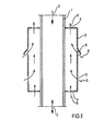
- the gas 6 entering or exiting through the openings flows due to convection or forced conveyance - by means of a fan - along the outer jacket of tube 1 through the gap between tube 1 and casing 3.
- By opening or closing the openings it is possible for the To change the gas flow rate 6 as a function of the tube wall temperature so that it neither exceeds nor falls below a predetermined temperature range.
- the connecting tubes 12 - designed as double tubes consist of the inner tubes 12a, in which the reaction gases, which are approx. 750-900 ° C., are transported from the reaction tubes to the collector, and the outer tubes 12b.
- the annular space between the inner and outer tubes is filled with thermal insulation materials 14.
- an intermediate pipe section 15 made of ferritic steel is welded in at the transition from the outer pipes 12b made of austenitic steel to the collector 13 made of ferritic steel, the resulting mixed weld seams 16 falling below the dew point ( ⁇ approx. 140 ° C.) of the reaction gas located in the annular space between the outer and inner tube, damage may occur due to corrosion.
- the individual outer tubes 12b are each surrounded with a coaxial sheath 17, which is connected to the outer tube 12b by an upper and lower end 18 and 19. In these closures, each evenly distributed, there are openings 20 and 21 which can be closed or opened by means of devices.
- gas 22, preferably air, is passed through these openings through the gap between the outer tube and the sheath for heat removal from the outer tube or for the supply of heat into the outer tube.
- gas 22 preferably air
- the flowing gas volume flow can be controlled as a function of the tube wall temperature in such a way that the tube wall temperature of the outer tubes is kept within the predetermined temperature range of approximately 400-140 ° C.
Landscapes
- Engineering & Computer Science (AREA)
- General Engineering & Computer Science (AREA)
- Mechanical Engineering (AREA)
- Physics & Mathematics (AREA)
- Thermal Sciences (AREA)
- Chemical & Material Sciences (AREA)
- Chemical Kinetics & Catalysis (AREA)
- Organic Chemistry (AREA)
- General Health & Medical Sciences (AREA)
- Combustion & Propulsion (AREA)
- Inorganic Chemistry (AREA)
- Health & Medical Sciences (AREA)
- Hydrogen, Water And Hydrids (AREA)
- Devices And Processes Conducted In The Presence Of Fluids And Solid Particles (AREA)
- Cooling Or The Like Of Electrical Apparatus (AREA)
- Heat-Exchange Devices With Radiators And Conduit Assemblies (AREA)
Description
- Die Erfindung betrifft ein Verfahren zur Wärmeabfuhr aus einem senkrecht angeordneten bzw. zur Wärmezufuhr in ein senkrecht angeordnetes Rohr beliebigen Querschnitts, das von einem Fluid hoher Temperatur durchströmt wird und von einer koaxialen Umhüllung umgeben ist, durch die ein Gasstrom geleitet wird. Ein derartiges Verfahren ist nach der US-A-2 937 923 bekannt.
- Bei einer häufig angewandten Ausführungsform werden als Rohre Doppelrohre verwendet, wobei in den Innenrohren der Transport des heißen Reaktionsgases stattfindet, und wobei die Außenrohre als druckaufnehmende Elemente ausgeführt sind. Der Ringraum zwischen beiden Rohren ist mit Wärmedämmstoffen ausgefüllt, um eine starke Erwärmung der Außenrohre und eine Temperaturerniedrigung des Reaktionsgases zu verhindern. Einerseits aufgrund von Werkstoffkennwerten, beispielsweise maximal zulässigen Festigkeitswerten, andererseits aufgrund von eventuellen Beschädigungen von Schweißverbindungen ausgelöst durch unterschiedliche Mechanismen ist es eine absolute Notwendigkeit, die Außenrohre in einem vorgegebenen Temperaturbereich von ca. 400 - 140° C zu halten. Einerseits sind solche Rohre häufig sich ändernden Witterungsbedingungen, wie Temperaturschwankungen, verschiedenen Windgeschwindigkeiten, Sonneneinstrahlung, etc. ausgesetzt, andererseits ändert sich der Wärmetransport pro Zeiteinheit in den Innenrohren wie beispielsweise bei hohem Durchsatz - also bei Vollast - oder bei geringem Durchsatz durch die Innenrohre oder während des Anfahrens oder Abstellens des Steamreformers. Eine Abkühlung unter beispielsweise ca. 140° C des im Ringraum zwischen Außen- und Innenrohr befindlichen Gases hat Taupunktunterschreitung desselben zur Folge, was aufgrund von Korrosion zu Schäden an den Außenrohren führt. Das Einhalten des Temperaturbereichs von ca. 400 - 140°C bei Änderung der oben erwähnten Wittetungsverhältnisse und bei Änderung der Bedingungen in den Innnenrohren war in der Vergangenheit nicht immer ausreichend gewährleistet; so kam es beispielsweise zu den beschriebenen Schäden, bevorzugt an Schweißnähten, was Undichtigkeiten der Außenrohre und damit längeren Ausfall des Steamreformers aufgrund aufwendiger Reparaturen zur Folge hatte.
- Ähnlich gelagerte Probleme können auch in Rohren, in denen chemische Reaktionen ablaufen, auftreten.
- Es stellte sich daher die Aufgabe, mittels einfacher und wirtschaftlicher Maßnahmen zu gewährleisten, daß ein vorgegebener Temperaturbereich an der Außenwand eines Rohres eingehalten wird.
- Diese Aufgabe wird erfindungsgemäß dadurch gelöst, daß zur Einhaltung eines vorgegebenen Temperaturbereiches an der Außenwand des Rohres die Menge des Gasstroms durch öffnen oder Schließen von in der Umhüllung angeordneten Öffnungen geändert wird.
- Weitere Merkmale des erfindungsgemäßen Verfahrens sind Gegenstand der abhängigen Ansprüche.
- Es versteht sich von selbst, daß die in den Patentansprüchen genannten erfinderischen Merkmale auch für ein Einzelrohr beliebigen Querschnitts - ohne Umhüllung durch Wärmedämmstoffe und ein zweites Rohr - Gültigkeit haben, und nicht speziell auf Rohre eines Steamreformers bzw. Reaktors beschränkt sind.
- Ein Ausführungsbeispiel der Erfindung mit den wesentlichen erfinderischen Merkmalen ist in der Zeichnung dargestellt und wird im folgenden näher beschrieben.
- Es zeigen
- Figur 1 einen Schnitt durch ein Einzelrohr
- Figur 2 einen Teilschnitt durch ein aus mehreren Einzelrohren bestehenden Rohrsystem eines Steamreformers (stark vereinfacht).
- Gemäß Figur 1 ist ein Rohr 1, durch das ein Fluid 2 mit hoher Temperatur und unterschiedlicher Strömungsgeschwindigkeit hindurchströmt, mit einer koaxialen Umhüllung 3 vergehen, die sowohl mit Öffnungen 4 im oberen und unteren Abschluß als auch mit Öffnungen 5 am Umfang der Umhüllung ausgestattet Ist. Das durch die Öffnungen ein- bzw. austretende Gas 6 strömt aufgrund von Konvektion oder Zwangsförderung - mittels eines Ventilators - entlang des Außenmantels des Rohres 1 durch den Spalt zwischen Rohr 1 und Umhüllung 3. Durch Öffnen bzw. Schließen der Öffnungen ist es möglich, den Gasmengenstrom 6 in Abhängigkeit der Rohrwandtemperatur so zu verändern, daß dieselbe einen vorgegebenen Temperaturbereich weder über- noch unterschreitet.
- Bei dem in Figur 2 vereinfacht dargestellten Ausschnitt aus einem Steamreformer müden eine Vielzahl von parallel und senkrecht verlaufenden Reaktionsrohren 11 - ausgelegt für Reaktionsabläufe bis ca. 10 bis 60 bar - über Verbindungsrohre 12 in einen Sammler 13. Die Verbindungsrohre 12 - ausgeführt als Doppelrohre bestehen aus den Innenrohren 12a, in denen der Transport der ca. 750 - 900° C heißen Reaktionsgase von den Reaktionsrohren zu dem Sammler erfolgt, und den Außenrohren 12b. Der Ringraum zwischen den Innen- und den Außenrohren ist mit Wärmedämmstoffen 14 ausgefüllt. Aus Fertigungsgründen wird beim Übergang der aus austenitischem Stahl bestehenden Außenrohre 12b zu dem aus ferritischem Stahl gefertigen Sammler 13 ein aus ferritischem Stahl bestehendes Zwischenrohrstück 15 eingeschweißt, wobei bei den daraus resultierenden Mischschweißnähten 16 bei Taupunktunterschreitung (< ca. 140°C) des im Ringraum zwischen Außen- und Innenrohr befindlichen Reaktionsgases, durch Korrosion Schäden auftreten. Um dies zu verhindern, werden die einzelnen Außenrohre 12b jeweils mit einer koaxialen Umhüllung 17 umgeben, die durch einen oberen und unteren Abschluß 18 und 19 mit dem Außenrohr 12b Verbunden ist. In diesen Abschlüssen, jeweils gleichmäßig verteilt, befinden sich Öffnungen 20 und 21, die mittels Vorrichtungen geschlossen oder geöffnet werden können. Erfindungsgemäß wird durch diese Öffnungen hindurch durch den Spalt zwischen Außenrohr und Umhüllung Gas 22, vorzugsweise Luft, zur Wärmeabfuhr aus dem Außenrohr bzw. zur Wärmezufuhr in das Außenrohr hindurchgeleitet. Durch Öffnen und Schließen und damit vermehrten bzw. verminderten Durchfluß an Gas ist der durchströmende Gasmengenstrom als Funktion der Rohrwandtemperatur derart steuerbar, daß die Rohrwandtemperatur der Außenrohre innerhalb des vorgegebenen Temperaturbereichs von ca. 400 - -140° C gehalten wird.
- In Abwandlung des oben Dargelegten ist es möglich, horizontal und parallel übereinander angeordnete Rohre, in denen heiße Gase strömen, mit einer einzigen sich über mehrere Rohre erstreckenden Umhüllung zu versehen, wobei gemäß dem erfindungsgemäßen Verfahren zur Wärmeabfuhr bzw. Wärmezufuhr, das zwischen Umhüllung und den Rohren strömende Gas nicht an einem einzigen Rohr, sondern an mehreren innerhalb einer Umhüllung angeordneten Rohren vorbeiströmt.
Claims (6)
Priority Applications (1)
| Application Number | Priority Date | Filing Date | Title |
|---|---|---|---|
| AT85103977T ATE35456T1 (de) | 1984-04-28 | 1985-04-02 | Verfahren zur waermeabfuhr aus einem bzw. zur waermezufuhr in ein senkrecht angeordnetes rohr. |
Applications Claiming Priority (2)
| Application Number | Priority Date | Filing Date | Title |
|---|---|---|---|
| DE19843415916 DE3415916A1 (de) | 1984-04-28 | 1984-04-28 | Verfahren zur waermeabfuhr aus einem bzw. zur waermezufuhr in ein senkrecht angeordnetes rohr |
| DE3415916 | 1984-04-28 |
Publications (3)
| Publication Number | Publication Date |
|---|---|
| EP0160225A2 EP0160225A2 (de) | 1985-11-06 |
| EP0160225A3 EP0160225A3 (en) | 1986-11-20 |
| EP0160225B1 true EP0160225B1 (de) | 1988-06-29 |
Family
ID=6234614
Family Applications (1)
| Application Number | Title | Priority Date | Filing Date |
|---|---|---|---|
| EP85103977A Expired EP0160225B1 (de) | 1984-04-28 | 1985-04-02 | Verfahren zur Wärmeabfuhr aus einem bzw. zur Wärmezufuhr in ein senkrecht angeordnetes Rohr |
Country Status (5)
| Country | Link |
|---|---|
| US (1) | US4830091A (de) |
| EP (1) | EP0160225B1 (de) |
| AT (1) | ATE35456T1 (de) |
| CA (1) | CA1273916A (de) |
| DE (2) | DE3415916A1 (de) |
Families Citing this family (21)
| Publication number | Priority date | Publication date | Assignee | Title |
|---|---|---|---|---|
| DE3813863A1 (de) * | 1988-04-23 | 1989-11-02 | Uhde Gmbh | Einrichtung zur aufnahme von katalysatoren, insbesondere bei der erzeugung von synthesegas |
| US5166727A (en) * | 1991-04-04 | 1992-11-24 | Konica Corporation | Structure for cooling process cartridge of image forming apparatus |
| DE4327176C1 (de) * | 1993-08-13 | 1995-01-26 | Metallgesellschaft Ag | Röhrenofen für die Erzeugung kohlenmonoxidhaltiger Gasgemische |
| US6245303B1 (en) | 1998-01-14 | 2001-06-12 | Arthur D. Little, Inc. | Reactor for producing hydrogen from hydrocarbon fuels |
| US7066973B1 (en) | 1996-08-26 | 2006-06-27 | Nuvera Fuel Cells | Integrated reformer and shift reactor |
| US6126908A (en) * | 1996-08-26 | 2000-10-03 | Arthur D. Little, Inc. | Method and apparatus for converting hydrocarbon fuel into hydrogen gas and carbon dioxide |
| US6986797B1 (en) | 1999-05-03 | 2006-01-17 | Nuvera Fuel Cells Inc. | Auxiliary reactor for a hydrocarbon reforming system |
| US6641625B1 (en) | 1999-05-03 | 2003-11-04 | Nuvera Fuel Cells, Inc. | Integrated hydrocarbon reforming system and controls |
| JP2006502938A (ja) | 2002-06-13 | 2006-01-26 | ヌヴェラ フューエル セルズ インコーポレイテッド | 優先的酸化反応装置の温度調整 |
| DE102004003003A1 (de) * | 2004-01-20 | 2005-09-01 | Basf Ag | Verfahren und Vorrichtung zur kontinuierlichen Herstellung einer chemischen Verbindung |
| KR100570752B1 (ko) * | 2004-02-26 | 2006-04-12 | 삼성에스디아이 주식회사 | 연료 전지 시스템의 개질기 및 이를 채용한 연료 전지시스템 |
| GB0513044D0 (en) | 2005-06-27 | 2005-08-03 | Saipem Uk Ltd | Pipe structure and methods of laying and use of a pipeline including such a pipe structure |
| US10760717B2 (en) | 2014-10-28 | 2020-09-01 | General Electric Technology Gmbh | Dissimilar metal connection and method for operating such a dissimilar metal connection |
| DE112017001485T5 (de) * | 2016-03-24 | 2018-12-06 | Mitsubishi Hitachi Power Systems, Ltd. | Kühlvorrichtung für Hochtemperaturrohr |
| CN106641541B (zh) * | 2016-12-21 | 2018-08-07 | 中国航天空气动力技术研究院 | 一种高温高压三通 |
| CN106895261A (zh) * | 2017-02-22 | 2017-06-27 | 峨眉山佳洁纸制品有限责任公司 | 循环蒸汽输送节能系统 |
| DE102017123606A1 (de) * | 2017-10-11 | 2019-04-11 | Norma Germany Gmbh | Verbinder |
| CN108194749A (zh) * | 2018-03-27 | 2018-06-22 | 江苏宏博机械制造有限公司 | 一种夹套式金属波纹管 |
| CN108548039B (zh) * | 2018-05-11 | 2019-10-29 | 上海科华热力管道有限公司 | 一种保温管及含有该保温管的自保温系统 |
| CN111569787B (zh) * | 2020-05-13 | 2022-04-22 | 万华化学集团股份有限公司 | 一种列管式固定床反应器及其在烯烃环氧化反应中的应用 |
| EP4628202A1 (de) | 2024-04-02 | 2025-10-08 | I.T.T. S.p.A. | Reaktorrohr mit katalysator und verfahren zum herunterladen des katalysators |
Family Cites Families (18)
| Publication number | Priority date | Publication date | Assignee | Title |
|---|---|---|---|---|
| FR421222A (fr) * | 1910-10-04 | 1911-02-17 | Alexandre Gustave Masse | Réfrigérant condenseur, refroidissant les mouts et liquides à l'abri de l'air |
| US1782435A (en) * | 1926-11-09 | 1930-11-25 | Gen Chemical Corp | Apparatus for cooling fluids |
| US2345423A (en) * | 1939-08-02 | 1944-03-28 | Pfannmuller Wilhelm | Apparatus for carrying out catalytic gas reactions |
| US2518583A (en) * | 1945-06-27 | 1950-08-15 | Universal Oil Prod Co | Catalytic reactor |
| US2937923A (en) * | 1957-10-18 | 1960-05-24 | Hercules Powder Co Ltd | Process for treatment of fluid reactants |
| US3334971A (en) * | 1964-08-18 | 1967-08-08 | Chemical Construction Corp | Catalytically reforming hydrocarbon and steam mixtures |
| US3645701A (en) * | 1967-06-19 | 1972-02-29 | Lummus Co | Reformer furnace |
| US3531263A (en) * | 1968-08-05 | 1970-09-29 | United Aircraft Corp | Integrated reformer unit |
| US3607130A (en) * | 1969-09-24 | 1971-09-21 | Exxon Research Engineering Co | Reformer furnace |
| US3656913A (en) * | 1970-01-27 | 1972-04-18 | Selas Corp Of America | Catalytic reactor |
| JPS5033977B1 (de) * | 1971-03-27 | 1975-11-05 | ||
| US3721531A (en) * | 1971-08-30 | 1973-03-20 | M Tuncer | Steam-hydrocarbon reformer with a support system for catalyst tubes therein |
| DE2509897A1 (de) * | 1975-03-07 | 1976-09-16 | Heinz Hoelter | Waermetauscher und grobstaub-abscheider fuer staubbeladenes heissgas |
| US4034803A (en) * | 1975-07-24 | 1977-07-12 | John Zink Company | Corrosion resistant tubular air preheater |
| JPS52112607A (en) * | 1976-03-09 | 1977-09-21 | Agency Of Ind Science & Technol | Reformers |
| US4203950A (en) * | 1977-12-27 | 1980-05-20 | United Technologies Corporation | Steam reforming reactor designed to reduce catalyst crushing |
| US4326582A (en) * | 1979-09-24 | 1982-04-27 | Rockwell International Corporation | Single element tube row heat exchanger |
| DE3429522C1 (de) * | 1984-08-10 | 1985-11-14 | Uhde Gmbh, 4600 Dortmund | Reaktionsrohrsystem eines Roehrenspaltofens |
-
1984
- 1984-04-28 DE DE19843415916 patent/DE3415916A1/de not_active Withdrawn
-
1985
- 1985-04-02 DE DE8585103977T patent/DE3563561D1/de not_active Expired
- 1985-04-02 EP EP85103977A patent/EP0160225B1/de not_active Expired
- 1985-04-02 AT AT85103977T patent/ATE35456T1/de not_active IP Right Cessation
- 1985-04-18 CA CA000479477A patent/CA1273916A/en not_active Expired - Lifetime
-
1988
- 1988-05-19 US US07/196,876 patent/US4830091A/en not_active Expired - Lifetime
Also Published As
| Publication number | Publication date |
|---|---|
| ATE35456T1 (de) | 1988-07-15 |
| EP0160225A2 (de) | 1985-11-06 |
| DE3563561D1 (en) | 1988-08-04 |
| EP0160225A3 (en) | 1986-11-20 |
| DE3415916A1 (de) | 1985-11-07 |
| US4830091A (en) | 1989-05-16 |
| CA1273916A (en) | 1990-09-11 |
Similar Documents
| Publication | Publication Date | Title |
|---|---|---|
| EP0160225A2 (de) | Verfahren zur Wärmeabfuhr aus einem bzw. zur Wärmezufuhr in ein senkrecht angeordnetes Rohr | |
| DE3022480C2 (de) | ||
| DE2008311C3 (de) | Wärmetauscher | |
| EP0251005B1 (de) | Gaskühler für Synthesegas | |
| DE2007528A1 (de) | Verfahren und Vorrichtung zur Gas fuhrung in Hochdruckwarmetauschern | |
| DE4128423A1 (de) | Vorrichtung zur durchfuehrung einer katalytischen reaktion | |
| DE2455508C2 (de) | Vorrichtung zum Erzeugen von Synthesegas durch Ausnutzen der in einem gasgekühlten Hochtemperaturreaktor gewonnenen Wärmeenergie | |
| DE3043853C2 (de) | Heißgaskühler mit einem Druckbehälter | |
| DE1542530C3 (de) | Röhrenspaltofen | |
| EP3032209A1 (de) | Quenchkühlsystem | |
| DE3913731A1 (de) | Waermetauscher zum kuehlen von spaltgas | |
| DE2317893A1 (de) | Vorrichtung zur durchfuehrung katalytischer endothermer reaktionen | |
| DE3538515C2 (de) | ||
| DE2459189C2 (de) | Wärmetauscher kreisförmigen Querschnitts für gasförmige Medien | |
| DE2536757C3 (de) | Dampferzeuger mit Beheizung durch Flüssigmetall | |
| EP0369556B1 (de) | Verfahren zur indirekten Erwärmung eines Prozessgasstroms in einem Reaktionsraum für eine endotherme Reaktion und Vorrichtung zu dessen Durchführung | |
| DE2624688C3 (de) | Wärmefibertraganlage für gasgekühlte Hochtemperaturreaktoren | |
| DE2431478A1 (de) | Waermetauscher zum einbau in eine atomreaktor-anlage | |
| DE3516958C2 (de) | ||
| DE3012596C2 (de) | ||
| DE2936199C2 (de) | Verfahren zur Überhitzung gasförmiger Medien | |
| DE2439224C3 (de) | Gasführungssystem für Gase hoher Temperatur und hohen Druckes | |
| DE102012008804A1 (de) | Durchlauf-Wärmebehandlungsofen mit gesteigerter Kühlleistung seiner Kühlzone und Verfahren hierzu | |
| DE2752472C2 (de) | Röhrenspaltofen zur Erzeugung von Wasserstoff mittels nuklear gewonnener Wärmeenergie | |
| EP0630397B1 (de) | Verfahren zum kühlen eines staubbeladenen rohgases aus der vergasung eines festen kohlenstoffhaltigen brennstoffes |
Legal Events
| Date | Code | Title | Description |
|---|---|---|---|
| PUAI | Public reference made under article 153(3) epc to a published international application that has entered the european phase |
Free format text: ORIGINAL CODE: 0009012 |
|
| AK | Designated contracting states |
Designated state(s): AT BE CH DE FR GB IT LI NL |
|
| PUAL | Search report despatched |
Free format text: ORIGINAL CODE: 0009013 |
|
| AK | Designated contracting states |
Kind code of ref document: A3 Designated state(s): AT BE CH DE FR GB IT LI NL |
|
| 17P | Request for examination filed |
Effective date: 19861210 |
|
| 17Q | First examination report despatched |
Effective date: 19870317 |
|
| GRAA | (expected) grant |
Free format text: ORIGINAL CODE: 0009210 |
|
| AK | Designated contracting states |
Kind code of ref document: B1 Designated state(s): AT BE CH DE FR GB IT LI NL |
|
| REF | Corresponds to: |
Ref document number: 35456 Country of ref document: AT Date of ref document: 19880715 Kind code of ref document: T |
|
| ITF | It: translation for a ep patent filed | ||
| GBT | Gb: translation of ep patent filed (gb section 77(6)(a)/1977) | ||
| REF | Corresponds to: |
Ref document number: 3563561 Country of ref document: DE Date of ref document: 19880804 |
|
| ET | Fr: translation filed | ||
| PLBE | No opposition filed within time limit |
Free format text: ORIGINAL CODE: 0009261 |
|
| STAA | Information on the status of an ep patent application or granted ep patent |
Free format text: STATUS: NO OPPOSITION FILED WITHIN TIME LIMIT |
|
| 26N | No opposition filed | ||
| ITTA | It: last paid annual fee | ||
| REG | Reference to a national code |
Ref country code: GB Ref legal event code: IF02 |
|
| PGFP | Annual fee paid to national office [announced via postgrant information from national office to epo] |
Ref country code: GB Payment date: 20040331 Year of fee payment: 20 |
|
| PGFP | Annual fee paid to national office [announced via postgrant information from national office to epo] |
Ref country code: NL Payment date: 20040406 Year of fee payment: 20 |
|
| PGFP | Annual fee paid to national office [announced via postgrant information from national office to epo] |
Ref country code: FR Payment date: 20040408 Year of fee payment: 20 |
|
| PGFP | Annual fee paid to national office [announced via postgrant information from national office to epo] |
Ref country code: DE Payment date: 20040415 Year of fee payment: 20 Ref country code: AT Payment date: 20040415 Year of fee payment: 20 |
|
| PGFP | Annual fee paid to national office [announced via postgrant information from national office to epo] |
Ref country code: CH Payment date: 20040416 Year of fee payment: 20 |
|
| PGFP | Annual fee paid to national office [announced via postgrant information from national office to epo] |
Ref country code: BE Payment date: 20040611 Year of fee payment: 20 |
|
| PG25 | Lapsed in a contracting state [announced via postgrant information from national office to epo] |
Ref country code: GB Free format text: LAPSE BECAUSE OF EXPIRATION OF PROTECTION Effective date: 20050401 |
|
| PG25 | Lapsed in a contracting state [announced via postgrant information from national office to epo] |
Ref country code: NL Free format text: LAPSE BECAUSE OF EXPIRATION OF PROTECTION Effective date: 20050402 |
|
| REG | Reference to a national code |
Ref country code: GB Ref legal event code: PE20 |
|
| REG | Reference to a national code |
Ref country code: CH Ref legal event code: PL |
|
| BE20 | Be: patent expired |
Owner name: *BASF A.G. Effective date: 20050402 |
|
| NLV7 | Nl: ceased due to reaching the maximum lifetime of a patent |
Effective date: 20050402 |
|
| BE20 | Be: patent expired |
Owner name: *BASF A.G. Effective date: 20050402 |