EP0160209A1 - Measurement of electrical signals with subpicosecond resolution - Google Patents
Measurement of electrical signals with subpicosecond resolution Download PDFInfo
- Publication number
- EP0160209A1 EP0160209A1 EP85103575A EP85103575A EP0160209A1 EP 0160209 A1 EP0160209 A1 EP 0160209A1 EP 85103575 A EP85103575 A EP 85103575A EP 85103575 A EP85103575 A EP 85103575A EP 0160209 A1 EP0160209 A1 EP 0160209A1
- Authority
- EP
- European Patent Office
- Prior art keywords
- crystal
- signal
- line
- field
- optical
- Prior art date
- Legal status (The legal status is an assumption and is not a legal conclusion. Google has not performed a legal analysis and makes no representation as to the accuracy of the status listed.)
- Granted
Links
Images


Classifications
-
- G—PHYSICS
- G01—MEASURING; TESTING
- G01R—MEASURING ELECTRIC VARIABLES; MEASURING MAGNETIC VARIABLES
- G01R13/00—Arrangements for displaying electric variables or waveforms
- G01R13/20—Cathode-ray oscilloscopes
- G01R13/22—Circuits therefor
- G01R13/34—Circuits for representing a single waveform by sampling, e.g. for very high frequencies
- G01R13/347—Circuits for representing a single waveform by sampling, e.g. for very high frequencies using electro-optic elements
-
- G—PHYSICS
- G01—MEASURING; TESTING
- G01R—MEASURING ELECTRIC VARIABLES; MEASURING MAGNETIC VARIABLES
- G01R1/00—Details of instruments or arrangements of the types included in groups G01R5/00 - G01R13/00 and G01R31/00
- G01R1/02—General constructional details
- G01R1/06—Measuring leads; Measuring probes
- G01R1/067—Measuring probes
- G01R1/07—Non contact-making probes
- G01R1/071—Non contact-making probes containing electro-optic elements
-
- G—PHYSICS
- G01—MEASURING; TESTING
- G01R—MEASURING ELECTRIC VARIABLES; MEASURING MAGNETIC VARIABLES
- G01R29/00—Arrangements for measuring or indicating electric quantities not covered by groups G01R19/00 - G01R27/00
- G01R29/02—Measuring characteristics of individual pulses, e.g. deviation from pulse flatness, rise time or duration
-
- G—PHYSICS
- G02—OPTICS
- G02F—OPTICAL DEVICES OR ARRANGEMENTS FOR THE CONTROL OF LIGHT BY MODIFICATION OF THE OPTICAL PROPERTIES OF THE MEDIA OF THE ELEMENTS INVOLVED THEREIN; NON-LINEAR OPTICS; FREQUENCY-CHANGING OF LIGHT; OPTICAL LOGIC ELEMENTS; OPTICAL ANALOGUE/DIGITAL CONVERTERS
- G02F1/00—Devices or arrangements for the control of the intensity, colour, phase, polarisation or direction of light arriving from an independent light source, e.g. switching, gating or modulating; Non-linear optics
- G02F1/01—Devices or arrangements for the control of the intensity, colour, phase, polarisation or direction of light arriving from an independent light source, e.g. switching, gating or modulating; Non-linear optics for the control of the intensity, phase, polarisation or colour
- G02F1/03—Devices or arrangements for the control of the intensity, colour, phase, polarisation or direction of light arriving from an independent light source, e.g. switching, gating or modulating; Non-linear optics for the control of the intensity, phase, polarisation or colour based on ceramics or electro-optical crystals, e.g. exhibiting Pockels effect or Kerr effect
- G02F1/0344—Devices or arrangements for the control of the intensity, colour, phase, polarisation or direction of light arriving from an independent light source, e.g. switching, gating or modulating; Non-linear optics for the control of the intensity, phase, polarisation or colour based on ceramics or electro-optical crystals, e.g. exhibiting Pockels effect or Kerr effect controlled by a high-frequency electromagnetic wave component in an electric waveguide
Definitions
- the present invention relates to methods and apparatus for measurement of electrical signals with subpicosecond resolution, and particularly to methods and apparatus for electro-optic sampling of electrical signals with the aid of an electro-optic crystal, the index of refraction of which changes in response to the electrical signalsin accordance with the Pockels effect.
- the invention makes it possible to measure transient electrical signals with subpicosecond resolution, thereby enabling the measurement of electrical signals having bandwidths in the tetrahertz range ( 10 12 Hz).
- the thickness of the crystal (h) has to be approximately of the order of 10 micrometers (about 14 micrometers when the effective dialectric constant, e * , is approximately 30). It is impractical to fabricate crystals with such a small thickness. While electro-optical sampling systems using traveling wave Pockel,cells are capable measuring signals containing frequencies up to many hundreds of gigahertz, with resolution in the picosecond range, even down to 0.5 picoseconds, it is desirable to even further extend the frequency range and the resolution of such electro-optic samplers. It is also desirable to provide electro-optic sampling where the transmission line is independent of or separate from the crystal. Then signals which are carried by lines, such as conductors on integrated circuit chip substrates, may be measured with high resolution.
- the extension of the frequency range and the temporal resolution of electro-optic sampling can be obtained through the use of the fringe field of a transmission line along which the electrical signals to be measured propagate.
- the crystal is disposed in the field and the optical beam is passed through the crystal oriented so that a component of its optical field is in parallel relationship with the field at a localized, small sampling point in the crystal.
- the transmission line may be a coplanar transmission line having a plurality of strips of conductive material disposed on a surface of the crystal.
- the optical sampling beam is focused so that its confocal region, where the optical wave front is planar, preferrably is close to the surface and perpendicular to the optical axis of the crystal.
- a sampling system of the type described in the above referenced publications is operable to measure signals with a bandwidth expanding to the tetrahertz range and with subpicosecond resolution.
- measurement of electrical signals with subpicosecond resolution in accordance with an embodiment the invention is responsive to such signals in a transmission line along which the signals propagate which creates an electric field adjacent to the line.
- An electro-optic crystal is disposed adjacent to and outside of the line so that the electrical field passes through at least a portion of the crystal and changes the index of refraction thereof in accordance with the Pockels effect.
- a beam of optical pulses is passed through the crystal to electro-optically sample the signal. The beam is passed in a direction transversely of the direction of the field to optically sample successively occurring portions of the signal as it propagates. The samples are then processed to provide a display of the signal with subpicosecond resolution.
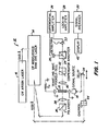
- FIG. 1 there is shown a system of the type described in the above identified publications. Reference may be had to these publications for more detailed description as to the design and operation of the system. Briefly, however, the system uses a traveling wave Pockekcell incorporating a electro-optic crystal of lithium tantalate or lithium niobate; lithium tantalate being presently preferred.
- This cell may utilize a coplanar waveguide on a surface thereof to provide a traveling wave Pockel cell, as will be described hereinafter in connection with FIGS. 2 and 3.
- the cell may also be formed by placing the electro-optic crystal adjacent to a transmission line existing on a substrate, such as the microstrip transmission line shown in FIG. 4 and the transmission lines of an integrated circuit, as shown in FIG. 5.
- the system utilizing the cell which is shown at 10 in FIG. 1 uses an optical pulse generator 12 made up of a colliding pulse mode-locked laser 14 pumped by a CW argon laser 16.
- the colliding pulse mode-locked laser is in the form of a ring dye laser.
- the laser 14 generates very short pulses, for example, 120 femto- seconds (fs) in duration at a 100 MHz rate. These pulses drive an electrical signal source 18 and also synchronously sample the electric field produced by the signal as it propagates across the crystal of the cell 10.
- TWo photodetectors 20 and 22 are used to measure the intensities of the transmitted and rejected beams at an analyzer 24.
- the signals from the detectors are processed by a differential amplifier 26, a lock-in amplifier 28 and a signal averager 30.
- the electro-optic sampling process is biased by a compensator 32 at the quarter wave point to achieve linear response and maximum voltage sensitivity.
- An optical delay device 34 enables temporal scanning of the entire electrical signal profile by the optical probe pulses of light from a polarizer 36 which is focused by a lens 38 in the crystal of the cell 10.
- Another lens 40 transmits the beam of pulses transmitted through the crystal to the compensator 32 and thence to the analyzer 24.
- a display 42 such as a CRT display, has its horizontal axis driven linearly with the delay line, and its vertical axis by the output from the signal averager 30. This results in a linear voltage versus equivalent time representation of the unknown electrical signal and requires no further processing.
- Relatively slow detectors can be used since their necessary bandwidth is dictated only by the frequency of a light chopper 44 used in conjunction with the lock-in amplifier 28.
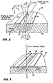
- FIG. 2 illustrates the traveling wave cell 10 provided'by an electro-optic crystal 46 with two conductive strips 48 and 50, one of which may be grounded, and both of which are disposed on a surface of the crystal 46.
- the electrical signal from the source may be applied to the coplanar parallel strip transmission line by a coaxial to strip line launcher.
- One launcher is connected to the source and the other to a terminating impedance (Z O ), as shown in FIG. 1.
- the drawing illustrates the direction of propagation of the signal which is triggered by a pulse from the laser 14 (FIG. 1).
- the drawing also shows the optical axis of the crystal.
- the optical pulse laser beam is focused by the.lens 38 so that its confocal region is adjacent to the surface of the crystal 46 on which the coplanar strip line conductors 48 and 50 are disposed.
- the conductors 48 and 50 may be very close together.
- the spacing can be extremely small. For example, less than 15 micrometers, spacing can be obtained without difficulty with conventional vapor deposition apparatus and appropriate masks.
- the beam size inside the crystal in the confocal region is less than the distance between the strip line conductors 48 and 50.
- the beam size inside the crystal therefore provides for subpicosecond temporal resolution of the signals.
- the signals have a fringe field which extends through the crystal.
- Three lines 52 show the direction of the field. These lines at the focusing point become parallel to the crystal axis 41 i.e., the optical axis of the crystal on which the strip lines are disposed.
- the strip lines are oriented so that the field due to the electrical signal is in parallel relationship with the optical axis of the crystal.
- the wavefronts in that region which are parallel to the beam axis 39 are planar. These planar wavefronts are perpendicular to the optical axis 41.
- the cell 10 shown therein is similar to the cell shown in FIG. 3 except that the coplanar waveguide is made up of three parallel conductive strips 54, 56 and 58. These strips and the crystal 46 constitute a balanced coplanar waveguide.
- the strips may be disposed close to each other so as to provide a field which is essentially parallel to the optical axis of the crystal 46 close to the surface on which the strips are deposited. Vapor deposition techniques may be used to deposit the strips so as to provide very close spacing therebetween.
- the two outer strips 54 and 56 serve as ground planes while the strip 58 carries the signal.
- Iaunchers may be used to connect the strips at one end of the crystal 46 to the source and at the other end to the terminating impedance. Further information as to such balanced coplanar waveguides may be obtained from an article by C.P. Wen, IEEE Transactions on Microwave Theory and Techniques, December 1969, pages 1087 to 1080.
- the laser probe beam is focused as by the lenses 38 and 40 (not shown in FIG. 3 to simplify the illustration) so that its confocal region is between the inner conductor 58 and one of the outer conductors, for example, the conductor 54, as shown in FIG. 3.
- FIG. 4 and 4a there is shown a cell utilizing an electro-optic crystal 60 without conductors on its surface and which is connected through a support 62 to a manipulator 64, suitably a micro-manipulator.
- The'crystal is disposed adjacent to the edge of a micro-strip conductor 66 with its end surface bearing upon a substrate 68 on which the micro-strip is deposited.
- the micro-strip conductor may work opposite a ground plane conductor 70 so as to provide a fringe field as illustrated by the lines 72 in FIG. 4a.
- the crystal 62 has a region adjacent to the edge of the micro-strip conductor 66.
- the sampling electro-optic beam is focused in the area indicated by the circle 74 in FIG.
- the optical field has a component parallel to the electric field and preferably, also to the optical axis of the crystal 60.
- the electrical signal propagates along the micro-strip and'is sampled in the crystal.
- the sampling beam goes to the compensator 32 (FIG. 1) and then to the rest of the sampling system so that the signals may be displayed. If a number of conductors are disposed on the substrate 68 the manipulator may be used to bring the crystal adjacent to the edges of these conductors so as to measure the electrical signals which propagate along such other conductors.
- FIG. 5 there is shown a substrate 76 on which integrated circuit components 78, for example active devices such as transistors and/or diodes are disposed.
- the signals are transmitted between the devices 78 by transmission lines provided by conductors 80.
- an electro-optic crystal 82 is placed with a surface thereof on the surface of the substrate 76 on which the devices 78 and the conductors 80 are disposed. The field from the conductors then penetrates the crystal.
- An optical probe beam is generated in the laser and transmits optical pulses to a polarizer 84.
- These pulses pass through a beam splitter 86 and are focused by a lens 88 to provide a confocal region 90 of the beam in the crystal where the field from one of the transmission lines 80 penetrates the crystal and produces the birefringence.
- the orientation of the beam is desirably such that a component of the optical field and a component of the electrical field are both parallel to the optical axis of the crystal 82.
- the surface of the crystal 82 which is juxtaposed on the surface of the substrate on which the devices 78 and the lines 80 are deposited, has a high reflection (HR) coating.
- the optical beam is feflected from this coating, passes back through the crystal 82, through the focusing lens 88 and is reflected by the beam splitter 86 to a polarization analyzer 92.
- the output beam then goes to the compensator 32 and the rest of the system shown in FIG. 1.
- the integrated circuit is operated in sychronism with the optical pulses through the delay 34 so as to develop outputs showing the profile of the electrical signals.
- the beam splitter 86 may be a polarization sensitive beam splitter which passes one polarization downwardly to the electro-optic crystal 82. The use of the polarizers and beam splitter may be avoided by tilting the beam with respect to the crystal 82 and the substrate 76. The reflected beam will then clear the lens 88 and go on to the compensator.
- the invention may be summarized as follows:
Abstract
Description
- The present invention relates to methods and apparatus for measurement of electrical signals with subpicosecond resolution, and particularly to methods and apparatus for electro-optic sampling of electrical signals with the aid of an electro-optic crystal, the index of refraction of which changes in response to the electrical signalsin accordance with the Pockels effect. The invention makes it possible to measure transient electrical signals with subpicosecond resolution, thereby enabling the measurement of electrical signals having bandwidths in the tetrahertz range (10 12 Hz).
- Sampling of an electrical signal with picosecond temporal resolution has been accomplished with the use of a traveling wave Pockels cell made up of an electro-optic crystal of lithium niobate or lithium tantalate on opposite surfaces of which a microwave strip, transmission line for the signals is provided. This system is described in United States Patent Application Serial No. 348,127 filed February 12, 1982 in the name of J. A. Valdmanis and G. Mourou and assigned to the same assignee as the present application. This application has been published under the Patent Cooperation Treaty as International Publication No. W083/02829 on August 18, 1983. The system is also the subject of an article entitled "Picosecond Electro-optic Sampling System" by J. A. Valdmanis et al., Appl. Phys. Lett., Vol. 41-3, 211, August 1982. It is desirable that only TEM or Qaasi-TEM modes of propagation take place in the traveling wave Pockel cell described in the above identified publications. Other modes can result in reflections which increase the noise in the sampling process in the cell and detract from the resolution of the system. The high end frequency cut-off for the TEM modes varies inversely with the thickness of the cell between the strip line conductors. The relationship is

- It has been discovered in accordance with the invention that the extension of the frequency range and the temporal resolution of electro-optic sampling can be obtained through the use of the fringe field of a transmission line along which the electrical signals to be measured propagate. The crystal is disposed in the field and the optical beam is passed through the crystal oriented so that a component of its optical field is in parallel relationship with the field at a localized, small sampling point in the crystal. The transmission line may be a coplanar transmission line having a plurality of strips of conductive material disposed on a surface of the crystal. The optical sampling beam is focused so that its confocal region, where the optical wave front is planar, preferrably is close to the surface and perpendicular to the optical axis of the crystal. Since the coplanar waveguide supports the transmission of electrical signals in the tetrahertz range and can easily be formed on the surface of the crystal, a sampling system of the type described in the above referenced publications is operable to measure signals with a bandwidth expanding to the tetrahertz range and with subpicosecond resolution.
- It is therefore an object of the present invention to provide improved methods and apparatus for the measurement of electrical signals by electro-optic sampling of the signals as they propagate along an electro-optic crystal capable of measurements in the subpicosecond range of signals having bandwidths extending to the tetrahertz range.
- It is a still further object of the present invention to provide methods and apparatus for measurement of electrical signals which propagate on lines (conductors) of integrated circuits by electro-optic sampling of the fringe field produced by such signals adjacent to the lines with the aid of electro-optic crystal.
- Briefly described, measurement of electrical signals with subpicosecond resolution in accordance with an embodiment the invention is responsive to such signals in a transmission line along which the signals propagate which creates an electric field adjacent to the line. An electro-optic crystal is disposed adjacent to and outside of the line so that the electrical field passes through at least a portion of the crystal and changes the index of refraction thereof in accordance with the Pockels effect. A beam of optical pulses is passed through the crystal to electro-optically sample the signal. The beam is passed in a direction transversely of the direction of the field to optically sample successively occurring portions of the signal as it propagates. The samples are then processed to provide a display of the signal with subpicosecond resolution.
- The foregoing and other objects, features and advantages of the invention as well as presently preferred embodiments thereof and the best modes presently known for carrying out the invention, will become more apparent from a reading of the following description in connection with the accompanying drawings in which:
- FIG. 1 is a block diagram of an electro-optic sampling system of the type described in the above referenced publications and utilizing a traveling waveguide Pocket cell so as to extend the resolution of the measurement and the high end cutoff frequency of electrical signals which can be sampled and measured;
- FIG. 2 is a perspective view, diagramatically showing a traveling wave Pockels cell which may be used in the system shown in FIG. 1, in accordance with one embodiment of the invention;
- FIG. 3 is a perspective view, diagramatically showing a traveling wave Pockels cell which may be used in the system shown in FIG. 1, in accordance with another embodiment of the invention;
- FIGS. 4 and 4a are a perspective and an enlarged sectional view illustrating the measurement of electrical signals using an electro-optic crystal in the fringe field of a micro-strip transmission line which provides a cell for electro-optic sampling of the electrical signal propagated along the micro-strip line using a sampling system such as illustrated in FIG. l; and
- FIG. 5 is a perspective view diagramatically illustrating the use of an electro-optic crystal by means of which signals propagating along lines of an integrated circuit may be sampled with the aid of a system such as shown in FIG. 1.
- Referring to FIG. 1 there is shown a system of the type described in the above identified publications. Reference may be had to these publications for more detailed description as to the design and operation of the system. Briefly, however, the system uses a traveling wave Pockekcell incorporating a electro-optic crystal of lithium tantalate or lithium niobate; lithium tantalate being presently preferred. This cell may utilize a coplanar waveguide on a surface thereof to provide a traveling wave Pockel cell, as will be described hereinafter in connection with FIGS. 2 and 3. The cell may also be formed by placing the electro-optic crystal adjacent to a transmission line existing on a substrate, such as the microstrip transmission line shown in FIG. 4 and the transmission lines of an integrated circuit, as shown in FIG. 5.
- The system utilizing the cell which is shown at 10 in FIG. 1 uses an
optical pulse generator 12 made up of a colliding pulse mode-locked laser 14 pumped by a CW argon laser 16. The colliding pulse mode-locked laser is in the form of a ring dye laser. The laser 14 generates very short pulses, for example, 120 femto- seconds (fs) in duration at a 100 MHz rate. These pulses drive an electrical signal source 18 and also synchronously sample the electric field produced by the signal as it propagates across the crystal of thecell 10.TWo photodetectors analyzer 24. The signals from the detectors are processed by adifferential amplifier 26, a lock-inamplifier 28 and a signal averager 30. The electro-optic sampling process is biased by acompensator 32 at the quarter wave point to achieve linear response and maximum voltage sensitivity. Anoptical delay device 34 enables temporal scanning of the entire electrical signal profile by the optical probe pulses of light from apolarizer 36 which is focused by alens 38 in the crystal of thecell 10. Anotherlens 40 transmits the beam of pulses transmitted through the crystal to thecompensator 32 and thence to theanalyzer 24. Adisplay 42, such as a CRT display, has its horizontal axis driven linearly with the delay line, and its vertical axis by the output from the signal averager 30. This results in a linear voltage versus equivalent time representation of the unknown electrical signal and requires no further processing. Relatively slow detectors can be used since their necessary bandwidth is dictated only by the frequency of a light chopper 44 used in conjunction with the lock-inamplifier 28. - FIG. 2 illustrates the
traveling wave cell 10 provided'by an electro-optic crystal 46 with twoconductive strips crystal 46. The electrical signal from the source may be applied to the coplanar parallel strip transmission line by a coaxial to strip line launcher. One launcher is connected to the source and the other to a terminating impedance (ZO), as shown in FIG. 1. The drawing illustrates the direction of propagation of the signal which is triggered by a pulse from the laser 14 (FIG. 1). The drawing also shows the optical axis of the crystal. The optical pulse laser beam is focused by the.lens 38 so that its confocal region is adjacent to the surface of thecrystal 46 on which the coplanarstrip line conductors conductors - The beam size inside the crystal in the confocal region is less than the distance between the
strip line conductors lines 52 show the direction of the field. These lines at the focusing point become parallel to thecrystal axis 41 i.e., the optical axis of the crystal on which the strip lines are disposed. The strip lines are oriented so that the field due to the electrical signal is in parallel relationship with the optical axis of the crystal. Cbnsidering the confocal region, the wavefronts in that region which are parallel to thebeam axis 39 are planar. These planar wavefronts are perpendicular to theoptical axis 41. - Referring to FIG. 3, the
cell 10 shown therein is similar to the cell shown in FIG. 3 except that the coplanar waveguide is made up of three parallelconductive strips crystal 46 constitute a balanced coplanar waveguide. The strips may be disposed close to each other so as to provide a field which is essentially parallel to the optical axis of thecrystal 46 close to the surface on which the strips are deposited. Vapor deposition techniques may be used to deposit the strips so as to provide very close spacing therebetween. The twoouter strips strip 58 carries the signal. Iaunchers may be used to connect the strips at one end of thecrystal 46 to the source and at the other end to the terminating impedance. Further information as to such balanced coplanar waveguides may be obtained from an article by C.P. Wen, IEEE Transactions on Microwave Theory and Techniques, December 1969, pages 1087 to 1080. - The laser probe beam is focused as by the
lenses 38 and 40 (not shown in FIG. 3 to simplify the illustration) so that its confocal region is between theinner conductor 58 and one of the outer conductors, for example, theconductor 54, as shown in FIG. 3. - Referring to FIG. 4 and 4a there is shown a cell utilizing an electro-
optic crystal 60 without conductors on its surface and which is connected through asupport 62 to amanipulator 64, suitably a micro-manipulator. The'crystal is disposed adjacent to the edge of amicro-strip conductor 66 with its end surface bearing upon asubstrate 68 on which the micro-strip is deposited. The micro-strip conductor may work opposite aground plane conductor 70 so as to provide a fringe field as illustrated by thelines 72 in FIG. 4a. Thecrystal 62 has a region adjacent to the edge of themicro-strip conductor 66. The sampling electro-optic beam is focused in the area indicated by thecircle 74 in FIG. 4a such that its optical field has a component parallel to the electric field and preferably, also to the optical axis of thecrystal 60. The electrical signal propagates along the micro-strip and'is sampled in the crystal. The sampling beam goes to the compensator 32 (FIG. 1) and then to the rest of the sampling system so that the signals may be displayed. If a number of conductors are disposed on thesubstrate 68 the manipulator may be used to bring the crystal adjacent to the edges of these conductors so as to measure the electrical signals which propagate along such other conductors. - Referring to FIG. 5 there is shown a
substrate 76 on whichintegrated circuit components 78, for example active devices such as transistors and/or diodes are disposed. The signals are transmitted between thedevices 78 by transmission lines provided byconductors 80. To make measurements of these signals an electro-optic crystal 82 is placed with a surface thereof on the surface of thesubstrate 76 on which thedevices 78 and theconductors 80 are disposed. The field from the conductors then penetrates the crystal. An optical probe beam is generated in the laser and transmits optical pulses to apolarizer 84. These pulses pass through a beam splitter 86 and are focused by a lens 88 to provide a confocal region 90 of the beam in the crystal where the field from one of thetransmission lines 80 penetrates the crystal and produces the birefringence. As in the other embodiments, the orientation of the beam is desirably such that a component of the optical field and a component of the electrical field are both parallel to the optical axis of thecrystal 82. The surface of thecrystal 82, which is juxtaposed on the surface of the substrate on which thedevices 78 and thelines 80 are deposited, has a high reflection (HR) coating. Accordingly, the optical beam is feflected from this coating, passes back through thecrystal 82, through the focusing lens 88 and is reflected by the beam splitter 86 to apolarization analyzer 92. The output beam then goes to thecompensator 32 and the rest of the system shown in FIG. 1. The integrated circuit is operated in sychronism with the optical pulses through thedelay 34 so as to develop outputs showing the profile of the electrical signals. The beam splitter 86 may be a polarization sensitive beam splitter which passes one polarization downwardly to the electro-optic crystal 82. The use of the polarizers and beam splitter may be avoided by tilting the beam with respect to thecrystal 82 and thesubstrate 76. The reflected beam will then clear the lens 88 and go on to the compensator. - From the foregoing description it will be apparent that there has been provided improved methods and apparatus for measurement of electrical signals having frequency components of very high frequency, in the tetrahertz range with temporal resolution in the subpicosecond range, both through the use of traveling wave cells having coplanar transmission lines and cells which may be placed adjacent transmission lines to detect the field therethrough. Variations and modifications in the herein described methods and apparatus, within the scope of the invention, will undoubtedly suggest themselves to those skilled in the art. Accordingly, the foregoing description should be taken as illustrative and not in a limiting sense.
- The invention may be summarized as follows:
- 1. The method of measuring an electrical signal with subpicosecond resolution which comprises the steps of propagating said signal along a transmission line which creates an electric field adjacent thereto, placing an electro-optic crystal adjacent and outside of said line so that said field passes through at least a portion of said crystal and changes the index of refraction thereof in accordance with the Pockels effect, passing a beam of optical pulses through said crystal in a direction transversely to the direction of said field to optically sample successively occurring portions of said signal, and processing said samples to provide a display of said signal.
- 2. The method according to 1 wherein said crystal has an optical axis, orienting said beam to bring a component of the optical field thereof into parallel relationship with said optical axis.
- 3. The method according to 1 including the step of orienting said beam and said line with respect to each other so that at least a component of the optical field of said beam and said electric field are in parallel relationship.
- 4. The method according to 3 including the step of orienting said crystal, beam and line with respect to each other so that the optical axis of said crystal, said electric field and a component of said optical field are in parallel relationship.
- 5. The method according to - 1 further comprising the step of focusing said beam to provide a region in said crystal where said beam is confocal.
- 6. The method according to 5 comprising the step of orienting said crystal and line with respect to each other so that said electric field and the optical field of said beam have components which are in parallel relationship.
- 7. The method according to 1 further comprising depositing the plurality of parallel strips of conductive material forming a coplanar transmission line on a surface of said crystal to place that crystal adjacent to said line, and focusing said beam in said crystal near said surface between said lines so that the confocal region where said electric field is parallel to a component of the optical field of said beam are in parallel relationship.
- 8. The method according to 7 wherein said plurality of said strips are three in number, grounding the outer ones of said strips, and applying said signal to the inner one of said strips, and said focusing step is carried out by focusing said beam in said crystal near the surface thereof between said inner and one of said outer ones of said strips.
- 9. The method according to 1 wherein said line is deposed on a substrate and said placing step is carried out by placing said crystal with one of its surfaces adjacent to said substrate and another of its surfaces adjacent to an edge of said line.
- 10. The method according to ' 1 wherein said line comprises a planar conductive element on the surface of a substrate, placing a reflective coating on a surface of said crystal, and placing said crystal with its reflective surface on said substrate, said passing step is carried out by passing said beam through a surface of said crystal opposite to the surface having said reflective coating so that said beam passes through said crystal to said reflective coating and is reflected from said coating to provide said samples for processing.
- ll. Apparatus for measuring an electrical signal with subpicosecond resolution which signal propagates said signal along a transmission line which creates an electric field adjacent thereto, said apparatus comprising an electro-optic crystal disposed adjacent and outside of said line so that said field passes through at least a portion of said crystal and changes the index of refraction thereof in accordance with the Pbckels effect, means for generating a beam of optical pulses synchronous with said signals and oriented to pass through said crystal in a direction transversely to the direction of said field to optically sample successively occurring portions of said signal, and means for processing said samples to provide a display of said signal.
- t 12. The apparatus according to 11 wherein said crystal has an optical axis, said beam having such orientation with respect to said optical axis that a component of the optical field of said beam is in parallel relationship with said optical axis.
- 13. The apparatus according to 11 including means for orienting said beam and said line with respect to each other so that at least a component of the optical field of said beam and said electric field are in parallel relationship.
- 14. The apparatus according to 13 wherein said line is in a plane parallel to said optical axis and extends in a direction perpendicular to said optical axis so that the optical axis, said electric field and a component of said optical field are in parallel relationship.
- 15. The apparatus according to 11 further comprising means for focusing said beam to provide a region in said crystal where said beam is confocal.
- 16. The apparatus according to 15 further comprising means for orienting said crystal and line and beam with respect to each other so that in said confocal region said electric field and the optical field of said beam have components which are in parallel relationship.
- 17. The apparatus according to 15 wherein said region is adjacent to the surface of said crystal on which said beam is incident.
- 18. The apparatus according to 11 wherein said line comprises plurality of parallel strips of conductive material forming a coplanar transmission line on a surface of said crystal and means for focusing said beam in said crystal near said surface between said lines so that the confocal region where said electric field is parallel to a component of the optical field of said beam are in parallel relationship.
- 19. The apparatus according to 18 wherein said plurality of said strips are three in number, the outer ones of said strips being grounded, means for applying said signal to the inner one of said strips, and said focusing means comprising means for focusing said beam in said crystal near the surface thereof between said inner and one of said outer ones of said strips.
- 20. The apparatus according to 11 wherein said line is deposed on a substrate, and said crystal is disposed with one of its surfaces adjacent to said substrate and another of its surfaces adjacent to an edge of said line.
- 21. The apparatus according to 11 wherein said line comprises a planar conductive element on the surface of a substrate, a reflective coating on a surface of said crystal, and said crystal is disposed with its reflective surface on said substrate, said beam is incident on a surface of said crystal opposite to the surface having said reflective coating so that said beam passes through said crystal to said reflective coating and is reflected from said coating to provide said samples to said processing means.
Claims (10)
Priority Applications (1)
| Application Number | Priority Date | Filing Date | Title |
|---|---|---|---|
| AT85103575T ATE46040T1 (en) | 1984-03-27 | 1985-03-26 | MEASUREMENT OF ELECTRICAL SIGNALS WITH A RESOLUTION OF SUBPICOSECONDS. |
Applications Claiming Priority (2)
| Application Number | Priority Date | Filing Date | Title |
|---|---|---|---|
| US06/593,992 US4603293A (en) | 1984-03-27 | 1984-03-27 | Measurement of electrical signals with subpicosecond resolution |
| US593992 | 1996-01-30 |
Publications (2)
| Publication Number | Publication Date |
|---|---|
| EP0160209A1 true EP0160209A1 (en) | 1985-11-06 |
| EP0160209B1 EP0160209B1 (en) | 1989-08-30 |
Family
ID=24377069
Family Applications (1)
| Application Number | Title | Priority Date | Filing Date |
|---|---|---|---|
| EP85103575A Expired EP0160209B1 (en) | 1984-03-27 | 1985-03-26 | Measurement of electrical signals with subpicosecond resolution |
Country Status (5)
| Country | Link |
|---|---|
| US (1) | US4603293A (en) |
| EP (1) | EP0160209B1 (en) |
| JP (1) | JPH0750128B2 (en) |
| AT (1) | ATE46040T1 (en) |
| DE (1) | DE3572735D1 (en) |
Cited By (11)
| Publication number | Priority date | Publication date | Assignee | Title |
|---|---|---|---|---|
| EP0197196A1 (en) * | 1985-03-08 | 1986-10-15 | The University Of Rochester | Electro-electron optical oscilloscope system for time-resolving picosecond electrical waveforms |
| EP0244248A2 (en) * | 1986-05-01 | 1987-11-04 | Tektronix, Inc. | Electro-optic sampler |
| FR2613084A1 (en) * | 1987-03-24 | 1988-09-30 | Univ Rochester | ELECTRO-OPTICAL SAMPLING DEVICE WITH POCKEL EFFECT AND METHOD FOR IMPLEMENTING THE SAME |
| EP0294817A2 (en) * | 1987-06-10 | 1988-12-14 | Hamamatsu Photonics K.K. | Voltage detecting device |
| EP0307936A1 (en) * | 1987-09-18 | 1989-03-22 | Hamamatsu Photonics K.K. | Multi-channel voltage detector |
| GB2210974A (en) * | 1987-10-13 | 1989-06-21 | Hamamatsu Photonics Kk | A voltage detector |
| GB2212265A (en) * | 1987-11-05 | 1989-07-19 | Hamamatsu Photonics Kk | A voltage detector |
| EP0346386A1 (en) * | 1987-03-03 | 1989-12-20 | The University Of Rochester | Electro-optic measurement (network analysis) system |
| FR2647551A1 (en) * | 1989-05-23 | 1990-11-30 | Univ Rochester | ELECTRO-OPTICAL PROBE FOR MEASURING SIGNALS OR ELECTRIC FIELDS AND ITS APPLICATION |
| US5055770A (en) * | 1989-04-12 | 1991-10-08 | Hamamatsu Photonics K. K. | Method and apparatus for detecting voltage |
| GB2246459A (en) * | 1988-09-03 | 1992-01-29 | Marconi Gec Ltd | Radio frequency spectrum analyser |
Families Citing this family (39)
| Publication number | Priority date | Publication date | Assignee | Title |
|---|---|---|---|---|
| US4681449A (en) * | 1984-09-07 | 1987-07-21 | Stanford University | High speed testing of electronic circuits by electro-optic sampling |
| FR2574943B1 (en) * | 1984-12-18 | 1987-05-22 | Thomson Csf | TRANSIENT ANALYZER SYSTEM |
| US4683420A (en) * | 1985-07-10 | 1987-07-28 | Westinghouse Electric Corp. | Acousto-optic system for testing high speed circuits |
| JPH0695108B2 (en) * | 1986-11-25 | 1994-11-24 | 浜松ホトニクス株式会社 | Circuit voltage detector |
| US4843586A (en) * | 1987-04-28 | 1989-06-27 | Hewlett-Packard Company | Distributed sampling of electrical and optical signals using coded switched electrode travelling wave modulators |
| JPS63292495A (en) * | 1987-05-25 | 1988-11-29 | Agency Of Ind Science & Technol | Optical-electric hybrid type associative storage device |
| JPH0695109B2 (en) * | 1987-05-30 | 1994-11-24 | 浜松ホトニクス株式会社 | Voltage detector |
| US4996475A (en) * | 1987-05-31 | 1991-02-26 | Hamamatsu Photonics Kabushiki Kaisha | Electro-optic voltage detector having a transparent electrode |
| JP2571385B2 (en) * | 1987-05-31 | 1997-01-16 | 浜松ホトニクス株式会社 | Voltage detector |
| JP2527965B2 (en) * | 1987-05-31 | 1996-08-28 | 浜松ホトニクス株式会社 | Voltage detector |
| JPH0695111B2 (en) * | 1987-06-05 | 1994-11-24 | 浜松ホトニクス株式会社 | Voltage detector |
| US4857836A (en) * | 1987-06-09 | 1989-08-15 | Siemens Aktiengesellschaft | Mechanical probe for optical measurement of electrical signals |
| JPH067240B2 (en) * | 1987-06-10 | 1994-01-26 | 浜松ホトニクス株式会社 | Optical associative memory |
| US5526298A (en) * | 1987-06-10 | 1996-06-11 | Hamamatsu Photonics K.K. | Optical associative memory |
| JPS63308572A (en) * | 1987-06-10 | 1988-12-15 | Hamamatsu Photonics Kk | Voltage detector |
| US5272434A (en) * | 1987-06-20 | 1993-12-21 | Schlumberger Technologies, Inc. | Method and apparatus for electro-optically testing circuits |
| JPH0830720B2 (en) * | 1987-06-30 | 1996-03-27 | 浜松ホトニクス株式会社 | Voltage detector |
| JPH0695114B2 (en) * | 1987-07-13 | 1994-11-24 | 浜松ホトニクス株式会社 | Voltage detector |
| JP2582579B2 (en) * | 1987-07-13 | 1997-02-19 | 浜松ホトニクス株式会社 | Voltage detector |
| JPS6446659A (en) * | 1987-08-17 | 1989-02-21 | Hamamatsu Photonics Kk | Voltage detector |
| JP2577581B2 (en) * | 1987-11-05 | 1997-02-05 | 浜松ホトニクス株式会社 | Voltage detector |
| JP2651682B2 (en) * | 1987-11-05 | 1997-09-10 | 浜松ホトニクス株式会社 | Voltage detection method |
| JP2689125B2 (en) * | 1988-02-25 | 1997-12-10 | 富士通株式会社 | LSI test equipment |
| JPH01320473A (en) * | 1988-06-22 | 1989-12-26 | Anritsu Corp | Electrooptic effect element and instrument for measuring waveform of electric signal using it |
| US4873485A (en) * | 1988-07-13 | 1989-10-10 | The University Of Rochester | Electro-optic signal measurement |
| JP2631138B2 (en) * | 1988-10-05 | 1997-07-16 | 浜松ホトニクス株式会社 | Voltage measuring device |
| US5142224A (en) * | 1988-12-13 | 1992-08-25 | Comsat | Non-destructive semiconductor wafer probing system using laser pulses to generate and detect millimeter wave signals |
| US5006789A (en) * | 1989-05-23 | 1991-04-09 | The University Of Rochester | Electro-optic signal measurement |
| US4978910A (en) * | 1989-06-26 | 1990-12-18 | At&T Bell Laboratories | Electrooptic apparatus for the measurement of ultrashort electrical signals |
| US5274325A (en) * | 1991-03-18 | 1993-12-28 | Nippon Telegraph And Telephone Corporation | Method and apparatus for electro-optic sampling measurement of electrical signals in integrated circuits |
| US5331275A (en) * | 1991-12-09 | 1994-07-19 | Fujitsu Limited | Probing device and system for testing an integrated circuit |
| EP1443337B1 (en) * | 1993-04-13 | 2006-03-01 | Agilent Technologies, Inc. | Electro-optic measuring instrument |
| US5583445A (en) * | 1994-02-04 | 1996-12-10 | Hughes Aircraft Company | Opto-electronic membrane probe |
| JP2810976B2 (en) * | 1994-11-28 | 1998-10-15 | 工業技術院長 | Electrical signal measuring method and apparatus |
| JPH11166952A (en) * | 1997-12-04 | 1999-06-22 | Jisedai Eisei Tsushin Hoso System Kenkyusho:Kk | High-frequency characteristic measurement method of dielectric material |
| US8155236B1 (en) * | 2002-06-21 | 2012-04-10 | Netlogic Microsystems, Inc. | Methods and apparatus for clock and data recovery using transmission lines |
| US7280190B1 (en) | 2006-06-21 | 2007-10-09 | Intel Corporation | Electro-optic time domain reflectometry |
| US20100038825A1 (en) * | 2006-12-21 | 2010-02-18 | Mcdonald Joel P | Methods of forming microchannels by ultrafast pulsed laser direct-write processing |
| JP7271283B2 (en) * | 2019-04-16 | 2023-05-11 | 株式会社日本マイクロニクス | Inspection connection device |
Citations (2)
| Publication number | Priority date | Publication date | Assignee | Title |
|---|---|---|---|---|
| WO1983002829A1 (en) * | 1982-02-12 | 1983-08-18 | Univ Rochester | Measurement of electrical signals with picosecond resolution |
| WO1983004107A1 (en) * | 1982-05-14 | 1983-11-24 | The University Of Rochester | Electron-optical wide band signal measurement system |
Family Cites Families (6)
| Publication number | Priority date | Publication date | Assignee | Title |
|---|---|---|---|---|
| US3313938A (en) * | 1962-05-18 | 1967-04-11 | Sylvania Electric Prod | Transmission line light modulator |
| US3432222A (en) * | 1964-09-30 | 1969-03-11 | Ibm | Optical scanning device |
| US3556663A (en) * | 1967-04-07 | 1971-01-19 | Cary Instruments | Automatic control of strain modulator |
| US4166669A (en) * | 1977-05-13 | 1979-09-04 | Massachusetts Institute Of Technology | Planar optical waveguide, modulator, variable coupler and switch |
| US4360865A (en) * | 1981-02-24 | 1982-11-23 | Pacific Measurements, Inc. | Broad band microwave detector |
| EP0067683B1 (en) * | 1981-06-12 | 1986-08-20 | Kabushiki Kaisha Meidensha | Electric field detector |
-
1984
- 1984-03-27 US US06/593,992 patent/US4603293A/en not_active Expired - Fee Related
-
1985
- 1985-03-26 DE DE8585103575T patent/DE3572735D1/en not_active Expired
- 1985-03-26 EP EP85103575A patent/EP0160209B1/en not_active Expired
- 1985-03-26 AT AT85103575T patent/ATE46040T1/en not_active IP Right Cessation
- 1985-03-26 JP JP60059693A patent/JPH0750128B2/en not_active Expired - Lifetime
Patent Citations (2)
| Publication number | Priority date | Publication date | Assignee | Title |
|---|---|---|---|---|
| WO1983002829A1 (en) * | 1982-02-12 | 1983-08-18 | Univ Rochester | Measurement of electrical signals with picosecond resolution |
| WO1983004107A1 (en) * | 1982-05-14 | 1983-11-24 | The University Of Rochester | Electron-optical wide band signal measurement system |
Cited By (19)
| Publication number | Priority date | Publication date | Assignee | Title |
|---|---|---|---|---|
| EP0197196A1 (en) * | 1985-03-08 | 1986-10-15 | The University Of Rochester | Electro-electron optical oscilloscope system for time-resolving picosecond electrical waveforms |
| EP0244248A2 (en) * | 1986-05-01 | 1987-11-04 | Tektronix, Inc. | Electro-optic sampler |
| EP0244248A3 (en) * | 1986-05-01 | 1989-07-19 | Tektronix, Inc. | Electro-optic sampler electro-optic sampler |
| EP0346386A1 (en) * | 1987-03-03 | 1989-12-20 | The University Of Rochester | Electro-optic measurement (network analysis) system |
| EP0346386A4 (en) * | 1987-03-03 | 1990-12-19 | The University Of Rochester | Electro-optic measurement (network analysis) system |
| FR2613084A1 (en) * | 1987-03-24 | 1988-09-30 | Univ Rochester | ELECTRO-OPTICAL SAMPLING DEVICE WITH POCKEL EFFECT AND METHOD FOR IMPLEMENTING THE SAME |
| EP0294817A2 (en) * | 1987-06-10 | 1988-12-14 | Hamamatsu Photonics K.K. | Voltage detecting device |
| EP0294817A3 (en) * | 1987-06-10 | 1990-07-25 | Hamamatsu Photonics K.K. | Voltage detecting device |
| EP0307936A1 (en) * | 1987-09-18 | 1989-03-22 | Hamamatsu Photonics K.K. | Multi-channel voltage detector |
| US4958124A (en) * | 1987-09-18 | 1990-09-18 | Hamamatsu Photonics Kabushiki Kaisha | Multi-channel voltage detector |
| US4962353A (en) * | 1987-10-13 | 1990-10-09 | Hamamatsu Photonics Kabushiki Kaisha | Voltage detector |
| GB2210974A (en) * | 1987-10-13 | 1989-06-21 | Hamamatsu Photonics Kk | A voltage detector |
| GB2210974B (en) * | 1987-10-13 | 1991-05-22 | Hamamatsu Photonics Kk | A voltage detector |
| GB2212265A (en) * | 1987-11-05 | 1989-07-19 | Hamamatsu Photonics Kk | A voltage detector |
| US4975635A (en) * | 1987-11-05 | 1990-12-04 | Hironori Takahashi | Voltage detector using a sampling type high-speed photodetector |
| GB2212265B (en) * | 1987-11-05 | 1991-11-13 | Hamamatsu Photonics Kk | A voltage detector |
| GB2246459A (en) * | 1988-09-03 | 1992-01-29 | Marconi Gec Ltd | Radio frequency spectrum analyser |
| US5055770A (en) * | 1989-04-12 | 1991-10-08 | Hamamatsu Photonics K. K. | Method and apparatus for detecting voltage |
| FR2647551A1 (en) * | 1989-05-23 | 1990-11-30 | Univ Rochester | ELECTRO-OPTICAL PROBE FOR MEASURING SIGNALS OR ELECTRIC FIELDS AND ITS APPLICATION |
Also Published As
| Publication number | Publication date |
|---|---|
| JPS60253878A (en) | 1985-12-14 |
| US4603293A (en) | 1986-07-29 |
| JPH0750128B2 (en) | 1995-05-31 |
| EP0160209B1 (en) | 1989-08-30 |
| ATE46040T1 (en) | 1989-09-15 |
| DE3572735D1 (en) | 1989-10-05 |
Similar Documents
| Publication | Publication Date | Title |
|---|---|---|
| EP0160209B1 (en) | Measurement of electrical signals with subpicosecond resolution | |
| US4618819A (en) | Measurement of electrical signals with subpicosecond resolution | |
| EP0101493B1 (en) | Measurement of electrical signals with picosecond resolution | |
| US4851767A (en) | Detachable high-speed opto-electronic sampling probe | |
| US5952818A (en) | Electro-optical sensing apparatus and method for characterizing free-space electromagnetic radiation | |
| KR100243779B1 (en) | Electric field sensor | |
| Valdmanis et al. | Picosecond and subpicosecond optoelectronics for measurements of future high speed electronic devices | |
| US4891580A (en) | Electro-optic measurements of voltage waveforms on electrical conductors | |
| US4745361A (en) | Electro-optic measurement (network analysis) system | |
| EP0668507A1 (en) | Electric field sensor | |
| JP3072814B2 (en) | Electro-optic probe and method of manufacturing the same | |
| US5670871A (en) | Polymeric film electrooptic sensor device | |
| US4873485A (en) | Electro-optic signal measurement | |
| EP0921404A2 (en) | High frequency characteristics measurement method for dielectric materials and high frequency circuit design method | |
| Valdmanis et al. | A non-contact picosecond prober for integrated circuit testing | |
| KR920000565B1 (en) | Electro-optic measurements of voltage waveforms on electrical conductors | |
| JP3063369B2 (en) | Magnetic field detector | |
| Bieler et al. | Realization of an ultra-broadband voltage pulse standard utilizing time-domain optoelectronic techniques | |
| JPH0787211B2 (en) | Integrated circuit test equipment | |
| Whitaker et al. | Electro-optic sampling and field mapping | |
| Circuits | Electro-Optic Measurement Techniques for Picosecond Materials, Devices | |
| Dykaar et al. | Al x Ga 1-x as probe for use in electro-optic sampling | |
| Forsyth et al. | Simple And Inexpensive Method For Testing High Speed Semiconductor Devices Using Electro-Optics Sampling | |
| David et al. | High resolution electro-optic measurements of 2-D field distributions inside MMIC devices | |
| JPH0933573A (en) | Probe for measuring instrument |
Legal Events
| Date | Code | Title | Description |
|---|---|---|---|
| PUAI | Public reference made under article 153(3) epc to a published international application that has entered the european phase |
Free format text: ORIGINAL CODE: 0009012 |
|
| AK | Designated contracting states |
Designated state(s): AT BE CH DE FR GB IT LI LU NL SE |
|
| 17P | Request for examination filed |
Effective date: 19860506 |
|
| 17Q | First examination report despatched |
Effective date: 19880307 |
|
| GRAA | (expected) grant |
Free format text: ORIGINAL CODE: 0009210 |
|
| AK | Designated contracting states |
Kind code of ref document: B1 Designated state(s): AT BE CH DE FR GB IT LI LU NL SE |
|
| PG25 | Lapsed in a contracting state [announced via postgrant information from national office to epo] |
Ref country code: SE Effective date: 19890830 Ref country code: NL Effective date: 19890830 Ref country code: LI Effective date: 19890830 Ref country code: IT Free format text: LAPSE BECAUSE OF FAILURE TO SUBMIT A TRANSLATION OF THE DESCRIPTION OR TO PAY THE FEE WITHIN THE PRESCRIBED TIME-LIMIT;WARNING: LAPSES OF ITALIAN PATENTS WITH EFFECTIVE DATE BEFORE 2007 MAY HAVE OCCURRED AT ANY TIME BEFORE 2007. THE CORRECT EFFECTIVE DATE MAY BE DIFFERENT FROM THE ONE RECORDED. Effective date: 19890830 Ref country code: CH Effective date: 19890830 Ref country code: BE Effective date: 19890830 Ref country code: AT Effective date: 19890830 |
|
| REF | Corresponds to: |
Ref document number: 46040 Country of ref document: AT Date of ref document: 19890915 Kind code of ref document: T |
|
| REF | Corresponds to: |
Ref document number: 3572735 Country of ref document: DE Date of ref document: 19891005 |
|
| ET | Fr: translation filed | ||
| REG | Reference to a national code |
Ref country code: CH Ref legal event code: PL |
|
| NLV1 | Nl: lapsed or annulled due to failure to fulfill the requirements of art. 29p and 29m of the patents act | ||
| PG25 | Lapsed in a contracting state [announced via postgrant information from national office to epo] |
Ref country code: LU Free format text: LAPSE BECAUSE OF NON-PAYMENT OF DUE FEES Effective date: 19900331 |
|
| PLBE | No opposition filed within time limit |
Free format text: ORIGINAL CODE: 0009261 |
|
| STAA | Information on the status of an ep patent application or granted ep patent |
Free format text: STATUS: NO OPPOSITION FILED WITHIN TIME LIMIT |
|
| 26N | No opposition filed | ||
| PGFP | Annual fee paid to national office [announced via postgrant information from national office to epo] |
Ref country code: FR Payment date: 19970122 Year of fee payment: 13 |
|
| PGFP | Annual fee paid to national office [announced via postgrant information from national office to epo] |
Ref country code: GB Payment date: 19970317 Year of fee payment: 13 |
|
| PGFP | Annual fee paid to national office [announced via postgrant information from national office to epo] |
Ref country code: DE Payment date: 19970326 Year of fee payment: 13 |
|
| PG25 | Lapsed in a contracting state [announced via postgrant information from national office to epo] |
Ref country code: GB Free format text: LAPSE BECAUSE OF NON-PAYMENT OF DUE FEES Effective date: 19980326 |
|
| PG25 | Lapsed in a contracting state [announced via postgrant information from national office to epo] |
Ref country code: FR Free format text: THE PATENT HAS BEEN ANNULLED BY A DECISION OF A NATIONAL AUTHORITY Effective date: 19980331 |
|
| GBPC | Gb: european patent ceased through non-payment of renewal fee |
Effective date: 19980326 |
|
| PG25 | Lapsed in a contracting state [announced via postgrant information from national office to epo] |
Ref country code: DE Free format text: LAPSE BECAUSE OF NON-PAYMENT OF DUE FEES Effective date: 19981201 |
|
| REG | Reference to a national code |
Ref country code: FR Ref legal event code: ST |