EP0159809A1 - Improvements in or relating to the forming of extrusion dies - Google Patents
Improvements in or relating to the forming of extrusion dies Download PDFInfo
- Publication number
- EP0159809A1 EP0159809A1 EP85301941A EP85301941A EP0159809A1 EP 0159809 A1 EP0159809 A1 EP 0159809A1 EP 85301941 A EP85301941 A EP 85301941A EP 85301941 A EP85301941 A EP 85301941A EP 0159809 A1 EP0159809 A1 EP 0159809A1
- Authority
- EP
- European Patent Office
- Prior art keywords
- die
- die piece
- extrusion
- aperture
- extension
- Prior art date
- Legal status (The legal status is an assumption and is not a legal conclusion. Google has not performed a legal analysis and makes no representation as to the accuracy of the status listed.)
- Withdrawn
Links
Images

Classifications
-
- B—PERFORMING OPERATIONS; TRANSPORTING
- B21—MECHANICAL METAL-WORKING WITHOUT ESSENTIALLY REMOVING MATERIAL; PUNCHING METAL
- B21C—MANUFACTURE OF METAL SHEETS, WIRE, RODS, TUBES, PROFILES OR LIKE SEMI-MANUFACTURED PRODUCTS OTHERWISE THAN BY ROLLING; AUXILIARY OPERATIONS USED IN CONNECTION WITH METAL-WORKING WITHOUT ESSENTIALLY REMOVING MATERIAL
- B21C25/00—Profiling tools for metal extruding
- B21C25/10—Making tools by operations not covered by a single other subclass
Definitions
- the invention relates to the forming of extrusion dies, such as dies used for extruding aluminium.
- the surface within the extrusion aperture which remains exposed is then removed by chemical or electro etching, so that the effective axial bearing depth of the extrusion aperture at any location around its periphery is determined by the depth to which the flowable material extends into the aperture at that location. Since the extent to which the flowable material flows into the extrusion aperture is inversely proportional to the resistance to flow at that location, the axial bearing depth of the completed die at that location is also inversely proportional to the resistance to flow, so that when the die is subsequently used for extrusion, there is substantially uniform rate of flow over the whole of the die aperture.
- the present invention provides improvements in the methods described and claimed in the above-mentioned European application.
- the different rates of flow in a material being extruded through a die depend, to a certain extent, on the overall variation in extruding pressure across the die aperture, regardless of the shape of the die. It is found that, in some circumstances, the methods as described in the above-mentioned patent application may not fully compensate for this variation in overall extrusion pressure (known as the "macro flow profile") and it is an object of the present invention to provide an improvement in the methods whereby this variation may be more effectively compensated for.
- the present invention provides a method of forming an extrusion die, of the kind comprising forming an extrusion aperture in a die piece, forcing a flowable material at least partly through the extrusion aperture so that the leading surface of the material becomes deformed in the extrusion direction, and then reshaping the die piece in such a manner that the axial bearing depth of the extrusion aperture at any location around its periphery corresponds to the deformation of the leading surface of the flowable material at that location, characterised by the additional step of adjusting the axial bearing depth at locations around the periphery of the extrusion aperture by amounts dependent on the distances of said locations from the centre of the die piece.
- the adjustment is carried out,before the aforesaid reshaping of the die piece in accordance with the deformation of the flowable material, by profiling the inlet end of the die piece to reduce the axial thickness of the die piece by an amount which increases with distance from the centre of the die piece.
- the inlet end of the die piece may be profiled by machining.
- said adjustment may be carried out by applying across the inlet end of the die piece, before the step of forcing the flowable material at least partly through the extrusion aperture, an extension having an aperture which registers with the extrusion aperture of the die piece,which extension has an axial thickness which increases with distance from the centre of the die, so that when the flowable material is forced through the extension and at least partly through the extension aperture in the die piece, the axial extent to which the flowable material extends into the die piece is, at any location, reduced by the axial thickness of the extension at that location, the extension subsequently being removed from the die piece before it is used in an extrusion process.
- the extension may comprise a preform which is applied to the die piece, or it may comprise a body which is cast in situ on the die piece. In either case the extension may, for example, be formed from wax or synthetic plastics material.
- the extension may be left in contact with the die piece during the etching process so as to protect the inlet end face of the die piece.
- the adjustment in axial bearing length may vary linearly from the centre to the circumference of the die.
- the ratio of axial bearing length reduction to distance from the centre of the die may be in the range 1:18 to 1:12.
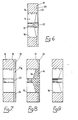
- the die piece 10 is formed with an extrusion aperture 11 comprising a central cylindrical portion 12 from which extend two narrower parallel-sided arm portions 13.
- Figure 1 shows a very simple form of extrusion aperture for the purposes of illustration only and that the principles of the invention are applicable to extrusion apertures of any shape and complexity, including apertures for extruding hollow sections.
- the dimensions of the aperture 11 are calculated in the usual way to allow for shrinkage and deflection of the die material during the extrusion process.
- the aperture will normally be electro-discharge machined in the die piece and then cleaned and polished.
- the die piece 10 is of constant axial thickness so that, initially, the extrusion aperture is of constant axial bearing depth.
- a suitable flowable compound 14 is forced partly into the extrusion aperture 11 by means of a piston (not shown) which simulates the action of an extrusion press.
- a probe (not shown) is located within the aperture to detect and indicate when the compound has been injected into the aperture to a pre-determined extent, the piston then being stopped so that extrusion ceases when the compound reaches the probe.
- the die is then reshaped, for example by subjecting it to an acid etching process or an electro-etching process so as to remove surface material from the interior of the extrusion aperture in the area between the line 16 and the outlet 15, as indicated at 18 in Figure 5.
- the compound 14 is preferably an acid resistant or electrically non-conductive material, as the case may be, so as to protect from etching the parts of the die aperture which the flowable material contacts.
- the exterior of the die also is coated or covered with an acid resistant or non-conductive material. Further details of the process are given in the above-mentioned European patent application.
- the effective bearing portion of the die is now only that portion which was protected by the compound 14 and which is of varying axial bearing depth. Since the axial bearing depth has been automatically adjusted according to the rate of flow through the untreated die piece, flow will then be substantially uniform over the whole of the extrusion aperture, thus substantially reducing the internal stresses in extrusions produced - by the die.
- the inlet end face 19 of the die piece is machined to form a circular recess 20 the bottom wall 21 of which slopes in the extruding direction as it extends from the centre 22 of the die towards the outer periphery.
- the effect of machining the end face of the die in this fashion is to reduce the effective axial bearing depth of the die at each location around the periphery of the aperture by an amount which increases in proportion to the distance of the location from the centre 22 of the die.
- the leading face of the compound since it is essentially flat, passes first into the central portion of the die aperture, and only subsequently enters the outer portions of the die.
- the extent to which the compound has projected into the aperture at any location is reduced by an amount equal to the axial depth of the recess 20 at that location. Since the recess 20 is of increasing depth towards the periphery of the die piece, the axial bearing depth is correspondingly reduced with distance from the centre of the die.
- the inclination of the bottom surface 21 of the recess 20 is preferably such that the ratio of reduction of axial bearing depth to distance from the centre of the die is in the range of 1:18 to 1:12.
- the sloping surface of the bottom of the recess is shown as linear, it may in some circumstances be curved.
- FIGS 7 to 9 illustrate an alternative method according to the invention.
- an extension 23 is applied to the inlet face 19 of the die piece 10 before the method of Figures 1 to 5 is carried out.
- the extension 23 is formed with an aperture 11a which registers exactly with the aperture 11 of the die piece.
- the rear surface 24 of the extension 23 is formed with a circular recess the axial depth of which decreases with distance from the centre line 22 of the die piece.
- the inclination of the bottom surface of the recess may be in the range of 1:18 to 1:12, as in the method of Figure 6.
- the extension 23 may be preformed as a unit and then applied to the die piece 10, or it may be moulded in situ against the die piece 10. It may be formed from wax or synthetic plastics material or from any other suitable material.
- the compound 14 is forced through the aperture 11a in the extension 23 and partly into the extrusion aperture 11 in the die piece as shown in Figure 8. In this case, however, the extent to which the flowable compound 14 projects into the aperture in the die piece 10 at any location is reduced by an amount equal to the thickness of the extrusion 23 at that location. Since the extension 23 is of increasing thickness towards the periphery of the die piece, the reduction in the extent to which the compound projects into the die piece 10 is greater nearer the periphery.
- the surface material is removed from the interior of the die aperture 11 by electro etching or chemical etching or by any other suitable method as described in the above-mentioned European patent specification.
- the extension 23 may be maintained in contact with the surface 19 of the die piece so as to protect that surface from etching.
- the effect of applying the shaped extension 23 to the die piece during the die forming process is to superimpose on the variation in axial bearing depth provided by the basic method a further variation in bearing depth which is dependent solely on the variation in extrusion pressure across the die piece.
- Both of the above described methods may result in a die piece where the axial bearing length of the extrusion aperture at each location is more closely correlated to the resistance to flow and extrusion pressure at that location, so as to result in more nearly uniform flow across the whole area of the extrusion aperture.
- a suitable material for use as the flowable compound in the methods according to the invention is an acid resistant paste sold under the trade name Sericol 922.
- Sericol 922 sold under the trade name Sericol 922.
- the die is baked to harden the paste.
- the exterior of the die is then protected with a lacquer and the die is then etched in aqua regia to remove the steel of the die piece from those areas of the aperture which are not contacted by the acid resistant paste.
- the Sericol 922 may subsequently be removed by sodium hydroxide solution, a solvent being used to strip the lacquer from the die.
- a silica powder (for example that sold under the trade name Aerosil) may be added to the Sericol 922 to increase the viscosity of the paste.
- An alternative flowable material which might be used is a resin of the kind which is cured by being subject to ultra violet light, such as the resin sold under the trade name UCB Resin T. Reaction setting resins may also be used.
- Another material suitable for use as the flowable compound is a material conventionally used to simulate aluminium flow behaviour when testing extrusion dies.
- This material comprises a material sold under the trade name Filia Wax with the.addition of 5% paraffin wax. This material may be used cold and has the advantage of being easy to handle and readily stripped from the die after etching.
Landscapes
- Engineering & Computer Science (AREA)
- Mechanical Engineering (AREA)
- Extrusion Moulding Of Plastics Or The Like (AREA)
- Extrusion Of Metal (AREA)
Applications Claiming Priority (2)
| Application Number | Priority Date | Filing Date | Title |
|---|---|---|---|
| GB848407273A GB8407273D0 (en) | 1984-03-21 | 1984-03-21 | Forming of extrusion dies |
| GB8407273 | 1984-03-21 |
Publications (1)
| Publication Number | Publication Date |
|---|---|
| EP0159809A1 true EP0159809A1 (en) | 1985-10-30 |
Family
ID=10558409
Family Applications (1)
| Application Number | Title | Priority Date | Filing Date |
|---|---|---|---|
| EP85301941A Withdrawn EP0159809A1 (en) | 1984-03-21 | 1985-03-20 | Improvements in or relating to the forming of extrusion dies |
Country Status (10)
| Country | Link |
|---|---|
| EP (1) | EP0159809A1 (da) |
| JP (1) | JPS611415A (da) |
| AU (1) | AU3987085A (da) |
| DK (1) | DK111485A (da) |
| ES (1) | ES8603146A1 (da) |
| FI (1) | FI851108L (da) |
| GB (1) | GB8407273D0 (da) |
| IL (1) | IL74710A0 (da) |
| NO (1) | NO851101L (da) |
| PT (1) | PT80150B (da) |
Cited By (1)
| Publication number | Priority date | Publication date | Assignee | Title |
|---|---|---|---|---|
| GB2362848A (en) * | 2000-04-01 | 2001-12-05 | Caton Internat Invest Ltd | Extrusion die |
Families Citing this family (1)
| Publication number | Priority date | Publication date | Assignee | Title |
|---|---|---|---|---|
| CN113084006B (zh) * | 2021-04-02 | 2023-04-25 | 中北大学 | 一种有效降低箱体成形载荷的分步挤压方法 |
Citations (6)
| Publication number | Priority date | Publication date | Assignee | Title |
|---|---|---|---|---|
| US1789675A (en) * | 1927-02-09 | 1931-01-20 | Ig Farbenindustrie Ag | Die extrusion method and apparatus |
| US2833406A (en) * | 1953-04-17 | 1958-05-06 | Schloemann Ag | Extrusion dies |
| DD126764A1 (da) * | 1976-07-20 | 1977-08-10 | ||
| DE2748392A1 (de) * | 1977-10-28 | 1979-05-03 | Degussa | Matrize zum strangpressen von eckigen profilen aus sproeden werkstoffen, insbesondere silbergraphit-werkstoffen |
| US4187443A (en) * | 1978-09-08 | 1980-02-05 | Rca Corporation | Color picture tube having improved corrugated apertured mask and method of making same |
| EP0095359A2 (en) * | 1982-05-25 | 1983-11-30 | Hobson Process Limited | Improvements in or relating to the forming of extrusion dies |
-
1984
- 1984-03-21 GB GB848407273A patent/GB8407273D0/en active Pending
-
1985
- 1985-03-12 DK DK111485A patent/DK111485A/da not_active Application Discontinuation
- 1985-03-14 AU AU39870/85A patent/AU3987085A/en not_active Abandoned
- 1985-03-20 EP EP85301941A patent/EP0159809A1/en not_active Withdrawn
- 1985-03-20 NO NO851101A patent/NO851101L/no unknown
- 1985-03-20 FI FI851108A patent/FI851108L/fi not_active Application Discontinuation
- 1985-03-21 ES ES541475A patent/ES8603146A1/es not_active Expired
- 1985-03-21 PT PT80150A patent/PT80150B/pt unknown
- 1985-03-22 JP JP60057648A patent/JPS611415A/ja active Pending
- 1985-03-25 IL IL74710A patent/IL74710A0/xx unknown
Patent Citations (6)
| Publication number | Priority date | Publication date | Assignee | Title |
|---|---|---|---|---|
| US1789675A (en) * | 1927-02-09 | 1931-01-20 | Ig Farbenindustrie Ag | Die extrusion method and apparatus |
| US2833406A (en) * | 1953-04-17 | 1958-05-06 | Schloemann Ag | Extrusion dies |
| DD126764A1 (da) * | 1976-07-20 | 1977-08-10 | ||
| DE2748392A1 (de) * | 1977-10-28 | 1979-05-03 | Degussa | Matrize zum strangpressen von eckigen profilen aus sproeden werkstoffen, insbesondere silbergraphit-werkstoffen |
| US4187443A (en) * | 1978-09-08 | 1980-02-05 | Rca Corporation | Color picture tube having improved corrugated apertured mask and method of making same |
| EP0095359A2 (en) * | 1982-05-25 | 1983-11-30 | Hobson Process Limited | Improvements in or relating to the forming of extrusion dies |
Cited By (3)
| Publication number | Priority date | Publication date | Assignee | Title |
|---|---|---|---|---|
| GB2362848A (en) * | 2000-04-01 | 2001-12-05 | Caton Internat Invest Ltd | Extrusion die |
| GB2362848B (en) * | 2000-04-01 | 2003-06-11 | Caton Internat Invest Ltd | Extrusion die |
| AU2001239446B2 (en) * | 2000-04-01 | 2006-04-06 | Preform Dies Limited | Extrusion die |
Also Published As
| Publication number | Publication date |
|---|---|
| PT80150A (en) | 1985-04-01 |
| DK111485A (da) | 1985-09-22 |
| JPS611415A (ja) | 1986-01-07 |
| NO851101L (no) | 1985-09-23 |
| FI851108A7 (fi) | 1985-09-22 |
| FI851108L (fi) | 1985-09-22 |
| AU3987085A (en) | 1985-09-26 |
| ES541475A0 (es) | 1985-12-16 |
| FI851108A0 (fi) | 1985-03-20 |
| ES8603146A1 (es) | 1985-12-16 |
| IL74710A0 (en) | 1985-06-30 |
| PT80150B (en) | 1986-10-28 |
| GB8407273D0 (en) | 1984-04-26 |
| DK111485D0 (da) | 1985-03-12 |
Similar Documents
| Publication | Publication Date | Title |
|---|---|---|
| US4387492A (en) | Plated jacket soft point bullet | |
| KR100374507B1 (ko) | 후방압출을 이용한 전단마찰인자의 측정방법 | |
| CA1123587A (en) | Method of reforming the fins of a finned tube | |
| DE3880095T2 (de) | Verfahren zur qualitaetsbeurteilung eines spritzgegossenen produktes. | |
| EP0159809A1 (en) | Improvements in or relating to the forming of extrusion dies | |
| EP0261523A2 (de) | Verfahren zur Herstellung eines Spritzgiesswerkzeugs | |
| US3150442A (en) | Method of making a nozzle | |
| DE69609693T2 (de) | Kolbenringpositionierungsvorrichtung und Kolbenstranggiessverfahren unter Verwendung dieser Vorrichtung | |
| EP0095359B1 (en) | Improvements in or relating to the forming of extrusion dies | |
| US3959872A (en) | Method for producing a core form to be employed in the molding of a ball joint bearing | |
| US4753413A (en) | Dies for making gooseneck or "J-tube" | |
| RS50141B (sr) | Kalup za istiskivanje i postupak njegovog pravljenja | |
| DE69606953T2 (de) | Verfahren zur Herstellung einer Form zum Spritzgiessen von optischen Teilen von Beleuchtungsvorrichtungen für Kraftfahrzeuge wobei gekrümmte Elemente angewendet werden | |
| JP3113577B2 (ja) | モールドベース | |
| CA2207389A1 (en) | Mold core-pin deflection transducer | |
| JP7726478B2 (ja) | ダイカスト製造方法及び装置 | |
| EP0269345A2 (en) | Method of moulding a micropipette | |
| RU2060096C1 (ru) | Стержень для получения полого слитка | |
| JP3345195B2 (ja) | 異形断面圧延材の板厚制御方法及び制御装置 | |
| SU1045977A1 (ru) | Инструмент дл волочени тонкостенных фасонных труб | |
| CN108638412B (zh) | 能防止模压时电缆线保护层溢出的模压方法及模压工装 | |
| KR810001069B1 (ko) | 아우트 서어트(out sert)성형법 | |
| NZ211540A (en) | Forming a tubular extrusion casting mould on a mandrel | |
| US3756061A (en) | Method of preforming materials which work-harden | |
| SU1227290A1 (ru) | Способ изготовлени полых изделий из листового металла |
Legal Events
| Date | Code | Title | Description |
|---|---|---|---|
| PUAI | Public reference made under article 153(3) epc to a published international application that has entered the european phase |
Free format text: ORIGINAL CODE: 0009012 |
|
| AK | Designated contracting states |
Designated state(s): AT BE CH DE FR GB IT LI LU NL SE |
|
| STAA | Information on the status of an ep patent application or granted ep patent |
Free format text: STATUS: THE APPLICATION IS DEEMED TO BE WITHDRAWN |
|
| 18D | Application deemed to be withdrawn |
Effective date: 19860801 |
|
| RIN1 | Information on inventor provided before grant (corrected) |
Inventor name: NICHOLSON, GEORGE RICHARD |