EP0159700A2 - Verfahren und Vorrichtung zur Untersuchung von Papierbahnen - Google Patents
Verfahren und Vorrichtung zur Untersuchung von Papierbahnen Download PDFInfo
- Publication number
- EP0159700A2 EP0159700A2 EP85104936A EP85104936A EP0159700A2 EP 0159700 A2 EP0159700 A2 EP 0159700A2 EP 85104936 A EP85104936 A EP 85104936A EP 85104936 A EP85104936 A EP 85104936A EP 0159700 A2 EP0159700 A2 EP 0159700A2
- Authority
- EP
- European Patent Office
- Prior art keywords
- target web
- web
- scanning angle
- impressions
- moving target
- Prior art date
- Legal status (The legal status is an assumption and is not a legal conclusion. Google has not performed a legal analysis and makes no representation as to the accuracy of the status listed.)
- Withdrawn
Links
Images


Classifications
-
- G—PHYSICS
- G02—OPTICS
- G02B—OPTICAL ELEMENTS, SYSTEMS OR APPARATUS
- G02B26/00—Optical devices or arrangements for the control of light using movable or deformable optical elements
- G02B26/08—Optical devices or arrangements for the control of light using movable or deformable optical elements for controlling the direction of light
- G02B26/10—Scanning systems
- G02B26/12—Scanning systems using multifaceted mirrors
-
- G—PHYSICS
- G01—MEASURING; TESTING
- G01N—INVESTIGATING OR ANALYSING MATERIALS BY DETERMINING THEIR CHEMICAL OR PHYSICAL PROPERTIES
- G01N21/00—Investigating or analysing materials by the use of optical means, i.e. using sub-millimetre waves, infrared, visible or ultraviolet light
- G01N21/84—Systems specially adapted for particular applications
- G01N21/88—Investigating the presence of flaws or contamination
- G01N21/89—Investigating the presence of flaws or contamination in moving material, e.g. running paper or textiles
- G01N21/8901—Optical details; Scanning details
Definitions
- the invention relates to methods and apparatus for the inspection of repeating patterns or designs on a moving web.
- the invention relates to inspection methods and apparatus wherein mirrors are cunted on a rotary drum of polygonal cross-section, a single mirror being mounted on each distinct outer side of the drum.
- Methods and apparatus of this type are described in U.S. Patent No. 3,089,381 issued to Bogert.
- the target web has customarily been positioned so that it is bisected by a line passing through the viewing point, i.e., the central point on the drum at which a viewing telescope is usually aimed.
- the viewing point i.e., the central point on the drum at which a viewing telescope is usually aimed.
- prior art rotating mirror drum methods and apparatus there were often provided 20 mirrors, one on each of 20 outer faces of the drum.
- the web normally the web consisted of two straight sections which met to form an angle of approximately 162 degrees, said web angle facing and being aligned with the central viewing point of the 20 mirror rotating drum.
- oscillating mirrors often located between the telescope sight line and the rotary prism, can only correct the images on the primary mirror through which the web is sighted.
- the extraneous images produced on a secondary mirror within the viewing area cannot receive the proper correction. This results in image movement or separation of two partial images which should be superimposed.
- the extraneous web images produced can lead to costly inspection errors as well as to viewer fatigue and uncertainty, and also restrict the speed at which the target web can move and still be reliably inspected.
- the invention comprises improved methods and apparatus for the inspection of continuous running webs, such as those used in the printing trade, wherein a rotating drum of mirrors, having a polygonal cross-section, rotates in time sequence with the moving web so as to allow inspection of the repeating image on the web such that the repeating image on the moving web appears stationary to the viewer.
- the target portion of the web is oriented with respect to the rotating drum so that a straight line bisecting the target portion of the web passes through a locus of points having as its center a point halfway between the center of the drum and the viewing point on the drum.
- the sweeping scanning angle thereby continuously maintains correspondence to one repeat length of the web.
- rotary prism 1 comprises a drum of polygonal cross-section wherein upon each outer side of the polygon is mounted a mirror.
- the rotary prism is adapted for rotation in a clockwise direction, as is depicted by the arrow.
- the prism rotates, there is a point 3 which is sighted by a viewer through telescope 4 and oscillating mirror 2.
- the image which appears to the viewer through the telescope is essentially that portion of the target web 7, to which sight lines B and D, from mirrors 6b and 6a, respectively are directed.
- each of mirrors 6a and 6b produce an image to the viewer (i.e., the images on the target web at the end of sight lines D and B).
- Some viewing corrections i.e., those described in Bogert U.S. Patent No. 3,098,381 are afforded by the oscillating mirror 2; however, such corrections operate only with respect to the one mirror through which the sight line 9 passes and have no effect with respect to the secondary mirror images.
- the target web 7 is centered on the viewing point 3 of the rotary prism so that the center line 11 which bisects the sweeping scanning angle 8 passes through the center of the target web 7.
- This design is typical of the prior art and necessarily implies that the sweeping scanning angle 8 will correspond to one repeat length of the target web only at a single instant, the instant that the sweeping scanning angle 8 is centered on the target web.
- the prism rotates, causing the sweeping scanning angle 8 to be not centered on the target web, but rather to engulf points B" and D", a viewer will see partial images in mirrors 6a and 6b.
- the separated image problem is intrinsic to the design of the prior art systems illustrated in Figure 1. This problem will be described more fully below with reference to Figures 5 and 6.
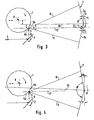
- Figure 2 illustrates one aspect of the invention, namely, the positioning of the target web 7, so that it is bisected by line 10, not the center line 11 (not shown) which passed through the viewing point 3 in the prior art.
- Line 10 is defined as follows: it is a line that passes through, i.e., bisects, the center of the target web and also the point halfway between rotary prism viewing point 3 and the center point K of the rotary prism 1.
- the sweeping scanning angle continues to correspond to one repeat length of the target web in small incremental distances above and below the points B' and D' on the target web, i.e., in the regions B"-B"' and D"-D'".
- the web angle 0 ⁇ is bisected by a line 10 which passes through the center of the web angle and also a point halfway between the viewing point 3 and the center K of the rotary prism 1.
- line 10 is parallel to the horizontal line, i.e., the line 12 which intersects the viewing point 3 and the point 33 directly opposite it on the target web 7.
- the amplitude of the bend in the target web can be determined for 20 mirror prisms based on desired web repeat lengths according to Table I.
- Figure 4 shows a further preferred embodiment of the invention wherein the line 10 which bisects the web angle 0 and passes through the point halfway between the rotary prism center K and the viewing point 3 is not parallel to the horizontal line, i.e., the line 12 which joins viewing point 3 and the point 33 (not shown) directly opposite it on the target web 7.
- web angles 10 and 11 should be chosen, for 20 mirror prisms, depending upon the desired web repeat length, according to Table II.
- Figures 5 and 6 illustrate the relationships between the sweeping scanning angle and the corresponding images on the moving target web as they existed in prior art systems and as they exist in systems according to the present invention, respectively.
- a target web 7 which comprises equidistant points I-J, J-K, K-L, L-M, M-N, N-I', I'-J', J'-K', K'-L', L'-M', M'-N', and N'-I".
- Points I and I', J and J', K and K', L and L', M and M', N and N', and I' and I" represent corresponding, i.e. repeating, points of a repeating web image.
- the web image repeat length for this embodiment is equal to any of the distances I-I', J-J', K-K', L-L', M-M', N-N', or I'-I".
- scanning angle positions 8, 18, and 28 are also illustrated in Figures 5 and 6 (hereinafter angles 8, 18 and 28, respectively).
- angles 8, 18 and 28 are also illustrated in Figures 5 and 6.
- the number of degrees in such scanning angles is a function of the number of mirrored sides on the rotating prism. For 20 mirror prisms, the scanning angle necessarily measures 36°.
- the points on the target web to which lines D and B of the scanning angle 8 are directed constitute the images provided to the viewer by the rotating prism mirrors 6a and 6b (shown previously).
- the viewer will see the image on the target web at the end of sight line B and will simultaneously see the image on the target web at the end of the sight line D.
- Figure 6 shows an embodiment of the invention wherein the line 10 bisecting the target web 7 passes through the point midway between the center K of the drum and the viewing point 3.
- a single, complete image is presented to the viewer not only when the scanning angle is centered on the target web (as is scanning angle 8) but also when the scanning angle is not centered on the web (for example, as with scanning angles 18 and 28).
- the images at the end of sight lines B and D, Bl and Dl, and B2 and D2 are the expected matching images at points L and L', K and K', and M and M', respectively.
- the present invention maintains a correspondence between the sweeping scanning angle and the web repeat length throughout the viewing area of the web by orienting the web as hereinbefore described.
- the scanning angle 8 defined by lines B and D in Figures 5 and 6, is constantly sweeping in a clockwise direction. In the preferred embodiments of the present invention, even though D and B both sweep in the clockwise direction, the correspondence between the sweeping scanning angle and one repeat length of the target web is maintained.
Landscapes
- Physics & Mathematics (AREA)
- General Physics & Mathematics (AREA)
- Optics & Photonics (AREA)
- Engineering & Computer Science (AREA)
- Textile Engineering (AREA)
- Health & Medical Sciences (AREA)
- Life Sciences & Earth Sciences (AREA)
- Chemical & Material Sciences (AREA)
- Analytical Chemistry (AREA)
- Biochemistry (AREA)
- General Health & Medical Sciences (AREA)
- Immunology (AREA)
- Pathology (AREA)
- Investigating Materials By The Use Of Optical Means Adapted For Particular Applications (AREA)
Applications Claiming Priority (2)
| Application Number | Priority Date | Filing Date | Title |
|---|---|---|---|
| US60273784A | 1984-04-23 | 1984-04-23 | |
| US602737 | 1984-04-23 |
Publications (2)
| Publication Number | Publication Date |
|---|---|
| EP0159700A2 true EP0159700A2 (de) | 1985-10-30 |
| EP0159700A3 EP0159700A3 (de) | 1987-08-19 |
Family
ID=24412598
Family Applications (1)
| Application Number | Title | Priority Date | Filing Date |
|---|---|---|---|
| EP85104936A Withdrawn EP0159700A3 (de) | 1984-04-23 | 1985-04-23 | Verfahren und Vorrichtung zur Untersuchung von Papierbahnen |
Country Status (1)
| Country | Link |
|---|---|
| EP (1) | EP0159700A3 (de) |
Cited By (1)
| Publication number | Priority date | Publication date | Assignee | Title |
|---|---|---|---|---|
| WO1989006787A1 (fr) * | 1988-01-12 | 1989-07-27 | Feldmühle Aktiengesellschaft | Dispositif d'inspection de bandes de materiaux plats se deplaçant a haute vitesse |
Family Cites Families (2)
| Publication number | Priority date | Publication date | Assignee | Title |
|---|---|---|---|---|
| US3089381A (en) * | 1959-05-08 | 1963-05-14 | Nat Lab And Mfg Corp | Inspection equipment |
| GB982664A (en) * | 1962-08-28 | 1965-02-10 | Marconi Co Ltd | Improvements in or relating to methods and apparatus for detecting surface faults and blemishes |
-
1985
- 1985-04-23 EP EP85104936A patent/EP0159700A3/de not_active Withdrawn
Cited By (2)
| Publication number | Priority date | Publication date | Assignee | Title |
|---|---|---|---|---|
| WO1989006787A1 (fr) * | 1988-01-12 | 1989-07-27 | Feldmühle Aktiengesellschaft | Dispositif d'inspection de bandes de materiaux plats se deplaçant a haute vitesse |
| US4933568A (en) * | 1988-01-12 | 1990-06-12 | Feldmuehle Aktiengesellschaft | Device for testing web-like planar structures moving at high speed |
Also Published As
| Publication number | Publication date |
|---|---|
| EP0159700A3 (de) | 1987-08-19 |
Similar Documents
| Publication | Publication Date | Title |
|---|---|---|
| US4756584A (en) | Scanning optical system with irregular deflecting surface correction | |
| EP2983030B1 (de) | Mehrebenenscanner und verfahren zum erfassen von objekten | |
| US4005926A (en) | Scanning device | |
| US4084881A (en) | Light beam scanning device | |
| EP0721128A1 (de) | Optische Anordnung für passive Abtastwinkelverdopplung | |
| US4487472A (en) | Light beam scanning apparatus | |
| US4632560A (en) | Method and apparatus for improved inspection of continuous webs | |
| JPH0772401A (ja) | 内側ドラムプロッタ | |
| CN1063851C (zh) | 级联扫描光学系统 | |
| EP0159700A2 (de) | Verfahren und Vorrichtung zur Untersuchung von Papierbahnen | |
| US4878720A (en) | Device for deflecting a bundle of light rays | |
| US4561778A (en) | Apparatus for measuring the dimensions of cylindrical objects by means of a scanning laser beam | |
| US3765742A (en) | Optical device | |
| DE3600578C1 (en) | Device for scanning a flat boundary surface of an object | |
| US5087983A (en) | Light scanning device | |
| US5867299A (en) | Cascade scanning optical system | |
| US4932733A (en) | Opto-mechanical analysis system using a single rotating polygon | |
| US5184246A (en) | Scanning of moving objects using unique polygon mounted on carousel which rotates at twice polygon's speed | |
| US4945287A (en) | Multiple pentaprism scanning device and method | |
| US4940312A (en) | Scanning prism | |
| US4933568A (en) | Device for testing web-like planar structures moving at high speed | |
| JP3088153B2 (ja) | 走査式描画装置 | |
| SU1115006A1 (ru) | Сканирующее устройство | |
| JPS5820410B2 (ja) | 光学的走査装置 | |
| JP2000121983A (ja) | レーザー走査装置 |
Legal Events
| Date | Code | Title | Description |
|---|---|---|---|
| PUAI | Public reference made under article 153(3) epc to a published international application that has entered the european phase |
Free format text: ORIGINAL CODE: 0009012 |
|
| AK | Designated contracting states |
Designated state(s): DE GB |
|
| PUAL | Search report despatched |
Free format text: ORIGINAL CODE: 0009013 |
|
| RHK1 | Main classification (correction) |
Ipc: G01N 21/89 |
|
| AK | Designated contracting states |
Kind code of ref document: A3 Designated state(s): DE GB |
|
| STAA | Information on the status of an ep patent application or granted ep patent |
Free format text: STATUS: THE APPLICATION IS DEEMED TO BE WITHDRAWN |
|
| 18D | Application deemed to be withdrawn |
Effective date: 19880220 |