EP0159577A2 - Control unit - Google Patents
Control unit Download PDFInfo
- Publication number
- EP0159577A2 EP0159577A2 EP85103872A EP85103872A EP0159577A2 EP 0159577 A2 EP0159577 A2 EP 0159577A2 EP 85103872 A EP85103872 A EP 85103872A EP 85103872 A EP85103872 A EP 85103872A EP 0159577 A2 EP0159577 A2 EP 0159577A2
- Authority
- EP
- European Patent Office
- Prior art keywords
- sliding
- control unit
- light
- base body
- unit according
- Prior art date
- Legal status (The legal status is an assumption and is not a legal conclusion. Google has not performed a legal analysis and makes no representation as to the accuracy of the status listed.)
- Withdrawn
Links
Images

Classifications
-
- B—PERFORMING OPERATIONS; TRANSPORTING
- B60—VEHICLES IN GENERAL
- B60H—ARRANGEMENTS OF HEATING, COOLING, VENTILATING OR OTHER AIR-TREATING DEVICES SPECIALLY ADAPTED FOR PASSENGER OR GOODS SPACES OF VEHICLES
- B60H1/00—Heating, cooling or ventilating devices
- B60H1/00642—Control systems or circuits; Control members or indication devices for heating, cooling or ventilating devices
- B60H1/0065—Control members, e.g. levers or knobs
-
- B—PERFORMING OPERATIONS; TRANSPORTING
- B60—VEHICLES IN GENERAL
- B60H—ARRANGEMENTS OF HEATING, COOLING, VENTILATING OR OTHER AIR-TREATING DEVICES SPECIALLY ADAPTED FOR PASSENGER OR GOODS SPACES OF VEHICLES
- B60H1/00—Heating, cooling or ventilating devices
- B60H1/00642—Control systems or circuits; Control members or indication devices for heating, cooling or ventilating devices
- B60H1/00814—Control systems or circuits characterised by their output, for controlling particular components of the heating, cooling or ventilating installation
- B60H1/00821—Control systems or circuits characterised by their output, for controlling particular components of the heating, cooling or ventilating installation the components being ventilating, air admitting or air distributing devices
- B60H1/00835—Damper doors, e.g. position control
- B60H1/00857—Damper doors, e.g. position control characterised by the means connecting the initiating means, e.g. control lever, to the damper door
-
- B—PERFORMING OPERATIONS; TRANSPORTING
- B60—VEHICLES IN GENERAL
- B60K—ARRANGEMENT OR MOUNTING OF PROPULSION UNITS OR OF TRANSMISSIONS IN VEHICLES; ARRANGEMENT OR MOUNTING OF PLURAL DIVERSE PRIME-MOVERS IN VEHICLES; AUXILIARY DRIVES FOR VEHICLES; INSTRUMENTATION OR DASHBOARDS FOR VEHICLES; ARRANGEMENTS IN CONNECTION WITH COOLING, AIR INTAKE, GAS EXHAUST OR FUEL SUPPLY OF PROPULSION UNITS IN VEHICLES
- B60K35/00—Instruments specially adapted for vehicles; Arrangement of instruments in or on vehicles
- B60K35/10—Input arrangements, i.e. from user to vehicle, associated with vehicle functions or specially adapted therefor
-
- B—PERFORMING OPERATIONS; TRANSPORTING
- B60—VEHICLES IN GENERAL
- B60Q—ARRANGEMENT OF SIGNALLING OR LIGHTING DEVICES, THE MOUNTING OR SUPPORTING THEREOF OR CIRCUITS THEREFOR, FOR VEHICLES IN GENERAL
- B60Q3/00—Arrangement of lighting devices for vehicle interiors; Lighting devices specially adapted for vehicle interiors
- B60Q3/10—Arrangement of lighting devices for vehicle interiors; Lighting devices specially adapted for vehicle interiors for dashboards
- B60Q3/14—Arrangement of lighting devices for vehicle interiors; Lighting devices specially adapted for vehicle interiors for dashboards lighting through the surface to be illuminated
-
- B—PERFORMING OPERATIONS; TRANSPORTING
- B60—VEHICLES IN GENERAL
- B60Q—ARRANGEMENT OF SIGNALLING OR LIGHTING DEVICES, THE MOUNTING OR SUPPORTING THEREOF OR CIRCUITS THEREFOR, FOR VEHICLES IN GENERAL
- B60Q3/00—Arrangement of lighting devices for vehicle interiors; Lighting devices specially adapted for vehicle interiors
- B60Q3/60—Arrangement of lighting devices for vehicle interiors; Lighting devices specially adapted for vehicle interiors characterised by optical aspects
- B60Q3/62—Arrangement of lighting devices for vehicle interiors; Lighting devices specially adapted for vehicle interiors characterised by optical aspects using light guides
- B60Q3/64—Arrangement of lighting devices for vehicle interiors; Lighting devices specially adapted for vehicle interiors characterised by optical aspects using light guides for a single lighting device
-
- B—PERFORMING OPERATIONS; TRANSPORTING
- B60—VEHICLES IN GENERAL
- B60Q—ARRANGEMENT OF SIGNALLING OR LIGHTING DEVICES, THE MOUNTING OR SUPPORTING THEREOF OR CIRCUITS THEREFOR, FOR VEHICLES IN GENERAL
- B60Q3/00—Arrangement of lighting devices for vehicle interiors; Lighting devices specially adapted for vehicle interiors
- B60Q3/60—Arrangement of lighting devices for vehicle interiors; Lighting devices specially adapted for vehicle interiors characterised by optical aspects
- B60Q3/62—Arrangement of lighting devices for vehicle interiors; Lighting devices specially adapted for vehicle interiors characterised by optical aspects using light guides
- B60Q3/66—Arrangement of lighting devices for vehicle interiors; Lighting devices specially adapted for vehicle interiors characterised by optical aspects using light guides for distributing light among several lighting devices
-
- F—MECHANICAL ENGINEERING; LIGHTING; HEATING; WEAPONS; BLASTING
- F16—ENGINEERING ELEMENTS AND UNITS; GENERAL MEASURES FOR PRODUCING AND MAINTAINING EFFECTIVE FUNCTIONING OF MACHINES OR INSTALLATIONS; THERMAL INSULATION IN GENERAL
- F16H—GEARING
- F16H19/00—Gearings comprising essentially only toothed gears or friction members and not capable of conveying indefinitely-continuing rotary motion
- F16H19/02—Gearings comprising essentially only toothed gears or friction members and not capable of conveying indefinitely-continuing rotary motion for interconverting rotary or oscillating motion and reciprocating motion
- F16H19/04—Gearings comprising essentially only toothed gears or friction members and not capable of conveying indefinitely-continuing rotary motion for interconverting rotary or oscillating motion and reciprocating motion comprising a rack
-
- Y—GENERAL TAGGING OF NEW TECHNOLOGICAL DEVELOPMENTS; GENERAL TAGGING OF CROSS-SECTIONAL TECHNOLOGIES SPANNING OVER SEVERAL SECTIONS OF THE IPC; TECHNICAL SUBJECTS COVERED BY FORMER USPC CROSS-REFERENCE ART COLLECTIONS [XRACs] AND DIGESTS
- Y10—TECHNICAL SUBJECTS COVERED BY FORMER USPC
- Y10S—TECHNICAL SUBJECTS COVERED BY FORMER USPC CROSS-REFERENCE ART COLLECTIONS [XRACs] AND DIGESTS
- Y10S116/00—Signals and indicators
- Y10S116/05—Signals and indicators using light guides
-
- Y—GENERAL TAGGING OF NEW TECHNOLOGICAL DEVELOPMENTS; GENERAL TAGGING OF CROSS-SECTIONAL TECHNOLOGIES SPANNING OVER SEVERAL SECTIONS OF THE IPC; TECHNICAL SUBJECTS COVERED BY FORMER USPC CROSS-REFERENCE ART COLLECTIONS [XRACs] AND DIGESTS
- Y10—TECHNICAL SUBJECTS COVERED BY FORMER USPC
- Y10T—TECHNICAL SUBJECTS COVERED BY FORMER US CLASSIFICATION
- Y10T74/00—Machine element or mechanism
- Y10T74/18—Mechanical movements
- Y10T74/18992—Reciprocating to reciprocating
-
- Y—GENERAL TAGGING OF NEW TECHNOLOGICAL DEVELOPMENTS; GENERAL TAGGING OF CROSS-SECTIONAL TECHNOLOGIES SPANNING OVER SEVERAL SECTIONS OF THE IPC; TECHNICAL SUBJECTS COVERED BY FORMER USPC CROSS-REFERENCE ART COLLECTIONS [XRACs] AND DIGESTS
- Y10—TECHNICAL SUBJECTS COVERED BY FORMER USPC
- Y10T—TECHNICAL SUBJECTS COVERED BY FORMER US CLASSIFICATION
- Y10T74/00—Machine element or mechanism
- Y10T74/20—Control lever and linkage systems
- Y10T74/20396—Hand operated
- Y10T74/20402—Flexible transmitter [e.g., Bowden cable]
- Y10T74/2042—Flexible transmitter [e.g., Bowden cable] and hand operator
- Y10T74/20426—Slidable
-
- Y—GENERAL TAGGING OF NEW TECHNOLOGICAL DEVELOPMENTS; GENERAL TAGGING OF CROSS-SECTIONAL TECHNOLOGIES SPANNING OVER SEVERAL SECTIONS OF THE IPC; TECHNICAL SUBJECTS COVERED BY FORMER USPC CROSS-REFERENCE ART COLLECTIONS [XRACs] AND DIGESTS
- Y10—TECHNICAL SUBJECTS COVERED BY FORMER USPC
- Y10T—TECHNICAL SUBJECTS COVERED BY FORMER US CLASSIFICATION
- Y10T74/00—Machine element or mechanism
- Y10T74/20—Control lever and linkage systems
- Y10T74/20396—Hand operated
- Y10T74/20468—Sliding rod
Definitions
- the invention is based on a control unit for setting heating, air conditioning and / or ventilation systems in motor vehicles according to the preamble of claim 1.
- Operating units of the generic type housed in the dashboard of motor vehicles are used, for example, used to open differently wide distribution flaps of outlets for cool or warm air in facilities of motor vehicles often referred to as air conditioning.
- the operation is mostly done via Bowden cables. It is often desirable to make the position of the actuating handle easily recognizable even in the dark by means of a color display as possible.
- An illuminated display of the respective operating position of the sliding members is provided in the control unit according to DE- ⁇ S 15 80 098.
- the sliding elements are guided in slots in a base body, the pins protruding from other slots transmitting the adjustment movement of the sliding elements via a lifting linkage to actuators, which in turn adjust the Bowden cables.
- Light strips are arranged on the front of the base body and extend over the entire adjustment path of each individual sliding link. From the outside they can be seen as a band of light.
- Each light bar is illuminated by a frame part made of translucent plastic, which collects the light rays and transmits them to the light guides.
- the light bar on the front face is wedge-shaped. Colored lighting can also be provided. However, it is not clear from this publication how this should be done.
- Another control unit for motor vehicles in which the actuating buttons of the sliding members are illuminated, is known from DE-GM 76 34 978.
- the sliding links are guided in slots in the base body.
- the light required for illuminating the actuation buttons reaches the actuation buttons via light carrier arms or light guides from a central light source after light deflection.
- the light guides are corrugated on the transition surfaces of the light, so that a scattering surface is created.
- the central light source is inserted in the opening of a block from which the light guides extend.
- a light-emitting diode serves as the light source and can emit both white and colored light.
- a light guide rod for the colored illumination of instruments in motor vehicles is described in DE-GM 80 04 562.
- a layer of paint with a thickness of 30 ⁇ m is applied to the reflection surface of the light guide rod.
- a separate light guide rod is required for each color.
- a light strip display arrangement with a thermometer scale-like display is also described in DE-OS 33 17 807.
- the position of the actuation handle is made visible by means of light segments arranged in a row and formed by the ends of light guides.
- the light guides emanate from a luminous center in a star shape.
- a light source is arranged in this lighting center. Ribbons are run between the light source and the light guide entry points, the length of which extends beyond the entire scale. This makes it possible to illuminate the entire scale in just one color. So that the ink ribbons do not overlap and there is a color falsification, an outlet opening is provided for the ink ribbons in the lighting center.
- a molded, slightly protruding guide ensures that there is no tilting of the ribbons.
- the ribbons and thus the guides are relatively long depending on the length of the sliding path of the actuation handle or according to the rotation of the rotary knob.
- the object of the present invention is to provide an operating unit of the type mentioned at the outset which has a structurally simple display device which is suitable only for sliding members, in which the individual smoothly guided ink ribbons are shorter than the sliding path of the sliding members and in which the risk of Overlapping of the ribbons and thus a color distortion is eliminated.
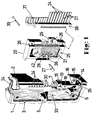
- a control unit is shown in a perspective view, as it is e.g. can be used to adjust heating, air conditioning and / or ventilation systems in motor vehicles.
- the embodiment shown here has two sliding links. With the help of these sliding elements, setting elements are usually actuated directly.
- the setting elements can be mechanical, e.g. Flaps, or electrical components, e.g. Motors, act. While the indirect actuation of the mechanical adjustment elements takes place via racks, cable drives, Bowden cables etc., the indirect actuation of the electrical adjustment elements is e.g. via potentiometers or switches operated by a slide. The level of the tapped voltage is a measure of the degree of adjustment.
- FIG. 1 denotes an elongated base body made of plastic with a U-shaped cross section, the reinforced side walls of which, as best seen in FIG. can be seen, each have an elongated recess 9.
- the reduction gear of a sliding member 4 is accommodated in each recess 9 and can be moved along the base body between two end positions.
- the sliding path of the sliding member 4 is limited by a projection 35 formed on the base body as a stop. Protrusions are expediently provided at both ends of the sliding path.
- the sliding member 4 consists of a U-shaped slide with a slide base 14.
- two holding members 15 are formed at a right angle to it, which on the front side of the slide base over a narrow Bridge 43 are connected to it in one piece.
- the holding members are resilient. This is important because there is a nose 16 at the free end of each holding member. After snapping in, these lugs serve to hold and guide the sliding member on the base body. The guidance takes place in such a way that the lugs 16 engage behind a web 17 which runs on the underside or rear of the base body 2 on the edge side.
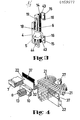
- the leg On the other side of the slide base, as shown in FIG. 3, the leg, which is at right angles, is formed by a first toothed rack which has internal teeth.
- a brake spring 19 is inserted into a depression 44 on the outside of the first rack 6. This brake spring is supported under pretension on the one hand on a wall of the recess 9 in the base body 2 and on the other hand on the sliding member 4 itself. With the preload, the desired sliding movement of the sliding member can be preselected within certain limits.
- an angle piece 18 is formed in alignment with it, which carries an actuating handle 5 at the angled, free end.
- the actuation handle 5 is laterally offset with respect to the slide base 14 and thus with respect to the part of the angle piece 18 which lies in the same plane as the slide base and extends through the slot formed between the base body 2 and the frame 3, so that a type of labyrinth seal is formed.
- a certain degree of protection of the interior against dirt is thereby achieved.
- another mechanical and electrical protection is given by the fact that you cannot get into the interior through the slot with a narrow object.
- the engine noise is dampened or, if you close the back of the control unit with a lid, greatly reduced.
- a linear drive with a reduction gear is located in the lateral recess 9 of the base body.
- This consists, among other things, of the first rack 6 of the sliding member 4 and a second rack 7, which, as shown in FIG. 2, on the lower wall of the recess 9 on the base body is trained.
- three gear wheels 8 are rotatably mounted between the two racks.
- Each gear 8 is attached to a pin 13, but so that it can rotate.
- the pins in turn are molded onto a rod 10 which is guided in a groove 11 on the bottom of the recess 9. As illustrated in FIG. 2, the pins 13 are perpendicular to the sliding direction of the rod 10.
- the gear wheels 8 rotate, the teeth of which engage both the teeth of the first rack 6 and the teeth of the second rack 7.
- the rod-e 10 also moves with the gearwheels. Due to this reduction gear, the sliding path of the rod is half the size of the sliding path of the sliding link. For this reason, the first rack 6 is approximately longer than half the sliding path of the sliding member 4. It is expedient to use at least three gear wheels in order to achieve a safe sliding gear. At the beginning and at the end of the sliding path of the sliding member in the vicinity of the stops, there are only two gears in each case in engagement with both racks. In the middle of the sliding path of the sliding member, the first rack 6 runs over all three gears.
- a Bowden cable can be connected to each rod 10.
- mechanical adjustment elements shown in the figures can be adjusted.
- an electrical connection can also be provided.
- the rod could e.g. be connected directly to the slide of a slide potentiometer.
- the voltage tapped by the contact spring is led via an electrical connection in the form of a printed circuit board or a cable directly or after conversion to an adjusting element which is adjusted according to the level of this voltage.
- the embodiment shown in Figure 1 has two sliding adjustment options, the base body 2 is covered by a frame 3 on the side and on the edge where the slot for the sliding member is located. If more than two sliding adjustment options are required, several base bodies can also be strung together and covered by a common frame, but always so that the existing slot is covered and protected by a frame web.
- a slot 31 extending in the sliding direction is recessed in the groove 11 at the bottom of the recess.
- a driver 32 which is integrally formed on the rod 10, projects into this slot 31.
- This driver 32 is located on the side of the rod opposite the pin 13.
- Connected to the driver 32 is an elongated sliding body 22, in the crack of which two ink ribbons 37 are clamped side by side.
- stiff color discs instead of ribbons, you could also use stiff color discs.
- the color display or the length of each ribbon is selected so that in the end positions of the sliding member, the light guide ends 24 visible in the frame 3 light up either only red or only blue.
- a lighting center 20 is arranged on the back of the U-shaped body? It consists, among other things, of an approximately rectangular socket body 25, which is made of plastic or metal. A semicircular depression 36 is cut out on the underside facing the base body. The light source 27, which is held in a lamp holder 28, projects into the hollow of this depression 36. This lamp holder can either be integrally formed on the holder body 25 or inserted as a separate lamp holder 28 in the holder body 25. The edge of the depression has many semicircular, radially running incisions 42. The light guides 21 are clamped into these incisions. The cross section of each light guide is rectangular with broad and long sides. The Light guides are arranged side by side so that their long sides lie close together. This allows them to optimally absorb a maximum of light.
- each ribbon is selected such that it is somewhat larger than the total distance of the light guides lying side by side. This ensures that all light guides light up in one color from the end stop.
- the furrow edge for the outgoing light guide is formed by a strip 38 in which the light guide is held.
- the socket body 25 and the strip 38 are fastened to the base body 2 by means of screws 39.
- the outgoing light guides which are led out of the bar are widened in spacing, bent at an angle of 90 and simultaneously rotated so that the broad ends of the light guide ends 24 lie side by side.
- the rotations of the light guides are of course different depending on their position in the row.
- the light guide ends 24 are visible in columns 30 on a long side of the frame 3 as a thermometer-scale display.
- a thermometer-scale display could also be on the other long side be provided in the same colors or in other colors. You would only need another lighting center for the other sliding link.
- a socket 29 is provided, by means of which the corresponding voltage for the light source 27 can be brought up.
- This socket can either be attached to the socket body as an individual part or it can be integrally formed with it.
- thermometer scale-like display it is often desirable to illuminate the entire front in a mostly white light.
- a recess 23 is provided on the front side of the base body 2, which receives a light guide body 33.
- the light guide body can be covered with a transparent film, if necessary, which is provided with a label and / or with symbols.
- the light guide body can consist of closely spaced individual light guides or a large single piece. You can choose between two design options for area lighting. Either elevations or incisions are made on the underside of the light guide body, at which the light is deflected and guided to the smooth surface.
- the light guide body receives the light from a light source 34, which e.g. designed as a sofa, as shown in FIG. 1, is located on a broad side of the base body.
Landscapes
- Engineering & Computer Science (AREA)
- Mechanical Engineering (AREA)
- Physics & Mathematics (AREA)
- Thermal Sciences (AREA)
- General Engineering & Computer Science (AREA)
- Chemical & Material Sciences (AREA)
- Combustion & Propulsion (AREA)
- Transportation (AREA)
- Mechanical Control Devices (AREA)
- Illuminated Signs And Luminous Advertising (AREA)
- Transmission Devices (AREA)
- Air-Conditioning For Vehicles (AREA)
Abstract
Die Erfindung beschreibt eine Bedieneinheit zum Einstellen von Heizungs-, Klima- und/oder Lüftungsanlagen in Kraftfahrzeugen. In einem länglichen Grundkörper sind zwischen zwei Endstellungen Schiebeglieder geführt. Mit Hilfe dieser Schiebeglieder werden durch Übertragungsmittel Einstellelemente, wie z.B. Klappen oder Motoren, eingestellt. Als Übertragungsmittel ist ein Untersetzungsgetriebe in der Form von Zahnstangen und Zahnrädern vorgesehen. Mit dem Schiebeglied wird auch ein Gleitkörper bewegt, an dem nebeneinander zwei Farbbänder befestigt sind. Diese Farbbänder sind zwischen Lichtleitern durchgeführt, wobei die Lichtleiterenden so angeordnet sind, daß sich eine thermometerskalaähnliche Anzeige ergibt.
Description
Die Erfindung geht von einer Bedieneinheit zum Einstellen von Heizungs-, Klima- und/oder Lüftungsanlagen in Kraftfahrzeugen nach dem Oberbegriff des Anspruches 1 aus.The invention is based on a control unit for setting heating, air conditioning and / or ventilation systems in motor vehicles according to the preamble of claim 1.
Im Armaturenbrett von Kraftfahrzeugen untergebrachte Bedieneinheiten der gattungsgemäßen Art werden unter anderem z.B. zum unterschiedlich weiten Öffnen von Verteiler-Klappen von Auslassen für kühle oder warme Luft in vielfach als Klimaanlage bezeichneten Einrichtungen der Kraftfahrzeuge verwendet. Die Betätigung erfolgt hierbei meistens über Bowdenzüge. Es ist dabei oftmals erwünscht, die Stellung der Betätigungshandhabe auch im Dunkeln durch eine möglichst farbige Anzeige leicht erkennbar zu machen.Operating units of the generic type housed in the dashboard of motor vehicles are used, for example, used to open differently wide distribution flaps of outlets for cool or warm air in facilities of motor vehicles often referred to as air conditioning. The operation is mostly done via Bowden cables. It is often desirable to make the position of the actuating handle easily recognizable even in the dark by means of a color display as possible.
Eine beleuchtete Anzeige der jeweiligen Betriebsstellung der Schiebeglieder ist bei der Bedieneinheit gemäß der DE-ÄS 15 80 098 vorgesehen. Die Schiebeglieder sind in Schlitzen eines Grundkörpers geführt, wobei die aus anderen Schlitzen herausragenden Zapfen die Verstellbewegung der Schiebeglieder über ein Hebergestänge auf Stellglieder, die ihrerseits die Bowdenzüge verstellen, übertragen. Auf der Vorderseite des Grundkörpers sind Lichtleisten angeordnet, die sich über den ganzen Verstellweg jedes einzelnen Schiebegliedes erstrecken. Von außen sind sie als Lichtband wahrzunehmen. Die Beleuchtung jeder Lichtleiste erfolgt über ein aus lichtdurchlässigem Kunststoff hergestellten Rahmenteil, das die Lichtstrahlen sammelt und an die Lichtleiter weiterleitet. Zur besseren Kenntlichmachung der Anfangs- und Endstellung des Schiebegliedes ist die Lichtleiste an der vorderen Stirnfläche keilförmig ausgebildet. Es kann auch eine farbige Beleuchtung vorgesehen sein. Es ist aus dieser Druckschrift jedoch nicht zu entnehmen, wie dies geschehen soll.An illuminated display of the respective operating position of the sliding members is provided in the control unit according to DE-ÄS 15 80 098. The sliding elements are guided in slots in a base body, the pins protruding from other slots transmitting the adjustment movement of the sliding elements via a lifting linkage to actuators, which in turn adjust the Bowden cables. Light strips are arranged on the front of the base body and extend over the entire adjustment path of each individual sliding link. From the outside they can be seen as a band of light. Each light bar is illuminated by a frame part made of translucent plastic, which collects the light rays and transmits them to the light guides. To make the start and end positions of the sliding link easier to identify, the light bar on the front face is wedge-shaped. Colored lighting can also be provided. However, it is not clear from this publication how this should be done.
Eine andere Bedieneinheit mit beleuchteten Betätigungsknöpfen ist in der DE-OS 32 06 288 beschrieben. Es sind ein oder mehrere Schiebeglieder vorhanden, die in Schlitzen des Grundkörpers geführt sind. Über einen Zwischenhebel wird durch das Schiebeglied ein Stellhebel betätigt, an dem ein Bowdenzug befestigt ist. Die außen auf den Schiebegliedern angebrachten Betätigungsknöpfe sind mittels beweglicher Lichtleiter beleuchtet. Die Lichtleiter gehen von einer Beleuchtungsquelle aus und sie sind mitten durch das Schiebeglied zum Betätigungsknopf geführt.Another control unit with illuminated actuation buttons is described in DE-OS 32 06 288. There are one or more sliding links which are guided in slots in the base body. An adjusting lever, to which a Bowden cable is attached, is actuated via an intermediate lever by the sliding member. The operating buttons on the outside of the sliding links are illuminated by means of movable light guides. The light guides start from a lighting source and are led through the middle of the sliding link to the actuation button.
Eine andere Bedieneinheit für Kraftfahrzeuge, bei der die Betätigungsknöpfe der Schiebeglieder beleuchtet sind, ist aus dem DE-GM 76 34 978 bekannt. Die Schiebeglieder sind.in Schlitzen des Grundkörpers geführt. Das für die Beleuchtung der Betätigungsknöpfe erforderliche Licht gelangt über Lichtträgerarme bzw. Lichtleiter von einer zentralen Lichtquelle aus nach Lichtumlenkungen zu den Betätigungsknöpfen. An den Übergangsflächen des Lichtes sind die Lichtleiter geriffelt, so daß eine Streufläche entsteht. Die zentrale Lichtquelle ist in die Öffnung eines Blockes eingesetzt, von dem aus die Lichtleiter ausgehen. Als Lichtquelle dient eine Lumineszenzdiode, die sowohl weißes als auch farbiges Licht aussenden kann.Another control unit for motor vehicles, in which the actuating buttons of the sliding members are illuminated, is known from DE-GM 76 34 978. The sliding links are guided in slots in the base body. The light required for illuminating the actuation buttons reaches the actuation buttons via light carrier arms or light guides from a central light source after light deflection. The light guides are corrugated on the transition surfaces of the light, so that a scattering surface is created. The central light source is inserted in the opening of a block from which the light guides extend. A light-emitting diode serves as the light source and can emit both white and colored light.
Ein Lichtleitstab zum farbigen Ausleuchten von Instrumenten in Kraftfahrzeugen ist in dem DE-GM 80 04 562 beschrieben. Auf die Reflexionsfläche des Lichtleitstabes ist eine Farbschicht von 30 pm Dicke aufgetragen. Über dieser Farbschicht befindet sich eine zweite weiße Schicht. Für jede Farbe wird ein eigener Lichtleitstab benötigt. Mit dieser vorgeschlagenen Lösung ist es nicht möglich, mit dem gleichen Lichtleitstab nacheinander zwei verschiedene Farbflächen zu erzeugen.A light guide rod for the colored illumination of instruments in motor vehicles is described in DE-GM 80 04 562. A layer of paint with a thickness of 30 μm is applied to the reflection surface of the light guide rod. There is a second white layer over this layer of paint. A separate light guide rod is required for each color. With this proposed solution, it is not possible to produce two different colored areas in succession with the same light guide rod.
Eine Leuchtbandanzeigeanordnung mit einer thermometerskalaähnlichen Anzeige ist auch in der DE-OS 33 17 807 beschrieben. Hierbei wird die Stellung der Betötigungshandhabe mittels in einer Reihe angeordneter Leuchtsegmente, die von den Enden von Lichtleitern gebildet werden, sichtbar gemacht. Die Lichtleiter gehen sternförmig von einem Leuchtzentrum aus. In diesem Leuchtzentrum ist eine Lichtquelle angeordnet. Zwischen Lichtquelle und Lichtleitereintrittsstellen sind Farbbänder geführt, deren Länge über die gesamte Skalaerstreckung hinausgeht. Damit ist es möglich, die gesamte Skala in nur einer Farbe zu beleuchten. Damit die Farbbänder sich nicht überlappen und sich eine Farbverfälschung ergibt, ist eine Austrittsöffnung für die Farbbänder im Leuchtzentrum vorgesehen. Eine angeformte, etwas in den Raum ragende Führung gewährleistet, daß kein Verkanten der Farbbänder vorkommt. Die Farbbänder und damit die Führungen sind entsprechend der Länge des Schiebeweges der Betötigungshandhabe oder entsprechend der Umdrehung des Drehknopfes relativ lang.A light strip display arrangement with a thermometer scale-like display is also described in DE-OS 33 17 807. The position of the actuation handle is made visible by means of light segments arranged in a row and formed by the ends of light guides. The light guides emanate from a luminous center in a star shape. A light source is arranged in this lighting center. Ribbons are run between the light source and the light guide entry points, the length of which extends beyond the entire scale. This makes it possible to illuminate the entire scale in just one color. So that the ink ribbons do not overlap and there is a color falsification, an outlet opening is provided for the ink ribbons in the lighting center. A molded, slightly protruding guide ensures that there is no tilting of the ribbons. The ribbons and thus the guides are relatively long depending on the length of the sliding path of the actuation handle or according to the rotation of the rotary knob.
Aufgabe der vorliegenden Erfindung ist es, eine Bedieneinheit nach der eingangs genannten Art zu schaffen, die eine konstruktiv einfache, eigens nur für Schiebeglieder geeignete Anzeigeeinrichtung aufweist, bei der die einzelnen reibungslos geführten Farbbänder kürzer als der Schiebeweg der Schiebeglieder sind und bei der die Gefahr des Überlappens der Farbbänder und damit eine Farbverfälschung beseitigt ist.The object of the present invention is to provide an operating unit of the type mentioned at the outset which has a structurally simple display device which is suitable only for sliding members, in which the individual smoothly guided ink ribbons are shorter than the sliding path of the sliding members and in which the risk of Overlapping of the ribbons and thus a color distortion is eliminated.
Diese Aufgabe wird erfindungsgemäß durch die im Kennzeichnungsteil des Anspruches 1 angegebenen Merkmale gelöst.This object is achieved by the features specified in the characterizing part of claim 1.
Vorteilhafte Ausgestaltungen ergeben sich aus den Unteransprüchen.Advantageous refinements result from the subclaims.
Die Erfindung wird nachfolgend für ein Ausführungsbeispiel anhand der Zeichnungen näher beschrieben.The invention is described below for an embodiment with reference to the drawings.
Von den Figuren zeigt
- Figur 1 eine perspektivische Vorderansicht einer Bedieneinheit in Explosionsdarstellung,
Figur 2 in Perspektivansicht im vergrößerten Maßstab teilweise aufgebrochen einen Teilausschnitt der Bedieneinheit,Figur 3 eine perspektivische Ansicht des Schiebegliedes mit Bremsfeder,Figur 4 eine perspektivische Ansicht eines rückwärtigen, schematisierten Teilausschnittes der Bedieneinheit.
- FIG. 1 shows a perspective front view of an operating unit in an exploded view,
- FIG. 2 shows a partial section of the operating unit, partly broken away, in a perspective view on an enlarged scale,
- FIG. 3 shows a perspective view of the sliding member with a brake spring,
- Figure 4 is a perspective view of a rear, schematic partial section of the control unit.
In Figur 1 ist in perspektivischer Darstellung eine Bedieneinheit gezeigt, wie sie z.B. zum Einstellen von Heizungs-, Klima- und/oder Lüftungsanlagen in Kraftfahrzeugen verwendet werden kann. Das hier dargestellte Ausführungsbeispiel besitzt zwei Schiebeglieder. Mit Hilfe dieser Schiebeglieder werden meist unmittelbar Einstellelemente betätigt. Bei den Einstellelementen kann es sich um mechanische, wie z.B. Klappen, oder elektrische Bauelemente, wie z.B. Motoren, handeln. Während die mittelbare Betätigung der mechanischen Einstellelemente über Zahnstangen, Seiltriebe, Bowdenzüge usw. erfolgt, wird die mittelbare Betätigung der elektrischen Einstellelemente z.B. über Potentiometer oder Schalter vorgenommen, die durch einen Schieber betätigt werden. Die Höhe der abgegriffenen Spannung ist ein Maß für den Grad der Einstellung.In Figure 1, a control unit is shown in a perspective view, as it is e.g. can be used to adjust heating, air conditioning and / or ventilation systems in motor vehicles. The embodiment shown here has two sliding links. With the help of these sliding elements, setting elements are usually actuated directly. The setting elements can be mechanical, e.g. Flaps, or electrical components, e.g. Motors, act. While the indirect actuation of the mechanical adjustment elements takes place via racks, cable drives, Bowden cables etc., the indirect actuation of the electrical adjustment elements is e.g. via potentiometers or switches operated by a slide. The level of the tapped voltage is a measure of the degree of adjustment.
In Figur 1 ist mit 2 ein länglicher, im Querschnitt U-förmiger Grundkörper aus Kunststoff bezeichnet, dessen verstärkte Seitenwandungen, wie am besten aus Figur 2 zu. erkennen ist, je eine längliche Aussparung 9 aufweisen. In jeder Aussparung 9 ist das Untersetzungsgetriebe eines SchiebegPiedes 4 untergebracht, das entlang des Grundkörpers zwischen zwei Endstellungen bewegbar ist. Begrenzt ist der Schiebeweg des Schiebegliedes 4 durch einen an den Grundkörper angeformten Vorsprung 35 als Anschlag. Zweckmäßigerweise sind an beiden Enden des Schiebeweges Vorsprünge vorgesehen.In FIG. 1, 2 denotes an elongated base body made of plastic with a U-shaped cross section, the reinforced side walls of which, as best seen in FIG. can be seen, each have an
Wie aus Figur 3 zu entnehmen ist, besteht das Schiebeglied 4 aus einem U-förmigen Schlitten mit einer Schlittenbasis 14. Auf der einen Seite der Schlittenbasis sind zu ihr in einem rechten Winkel zwei Halteglieder 15 angeformt, die an der Stirnseite der Schlittenbasis über eine schmale Brücke 43 mit ihr einstückig verbunden sind. Durch diese Art Verbindung sind die Halteglieder federnd ausgebildet. Dies ist deshalb von Bedeutung, da am freien Ende jedes Haltegliedes eine Nase 16 vorhanden ist. Diese Nasen dienen nach dem Einschnappen zur Halterung und Führung des Schiebegliedes am Grundkörper. Die Führung erfolgt hierbei so, daß die Nasen 16 einen Steg 17 hintergreifen, der auf der Unterseite bzw. Rückseite des Grundkörpers 2 randseitig verläuft.As can be seen from Figure 3, the sliding
Auf der anderen Seite der Schlittenbasis wird, wie Figur 3 zeigt, der im rechten Winkel stehende Schenkel von einer ersten Zahnstange gebildet, die eine Innenverzahnung aufweist. Auf der Außenseite der ersten Zahnstange 6 ist eine Bremsfeder 19 in eine Einsenkung 44 eingesetzt. Diese Bremsfeder stütz-t sich unter Vorspannung zum einen an einer Wand der Aussparung 9 im Grundkörper 2 und zum anderen an dem Schiebeglied 4 selbst ab. Mit der Vorspannung kann der gewünschte Schiebegang des Schiebegliedes in bestimmten Grenzen vorgewählt werden.On the other side of the slide base, as shown in FIG. 3, the leg, which is at right angles, is formed by a first toothed rack which has internal teeth. A
In Verlängerung der Schlittenbasis 14 ist mit ihr fluchtend ein Winkelstück 18 angeformt, das am abgewinkelten, freien Ende eine Betätigungshandhabe 5 trägt. Die Betötigungshandhabe 5 ist gegenüber der Schlittenbasis 14 und damit gegenüber dem in der gleichen Ebene wie die Schlittenbasis liegenden und dem zwischen Grundkörper 2 und Blendrahmen 3 gebildeten Schlitz hindurchragenden Teil des Winkelstücks 18 seitlich versetzt, so daß eine Art Labyrinthdichtung entsteht. Damit wird ein gewisser Schutz des Inneren vor Verschmutzung erreicht. Außerdem ist ein weiterer sowohl mechanischer als auch elektrischer Schutz dadurch gegeben, daß man nicht mit einem schmalen Gegenstand durch den Schlitz in das Innere gelangen kann. Ferner werden die Motorgeräusche gedämpft oder, falls man die Rückseite der Bedieneinheit mit einem Deckel verschließt, stark herabgesetzt.In an extension of the
In der seitlichen Aussparung 9 des Grundkörpers befindet sich ein Linearantrieb mit einem Untersetzungsgetriebe. Dieses besteht unter anderem aus der ersten Zahnstange 6 des Schiebegliedes 4 und einer zweiten Zahnstange 7, die, wie Figur 2 zeigt, an der unteren Wand der Aussparung 9 am Grundkörper ausgebildet ist. Zwischen beiden Zahnstangen sind bei dem in den Figuren dargestellten Ausführungsbeispiel drei Zahnräder 8 drehbar gelagert. Selbstverständlich sind auch Ausführungsbeispiele denkbar, bei denen mehr Zahnräder vorhanden sind. Jedes Zahnrad 8 ist an einem Zapfen 13 befestigt, jedoch so, daß es sich drehen kann. Die Zapfen ihrerseits sind an einer Stange 10 angespritzt, die in einer Nut 11 am Boden der Aussparung 9 geführt ist. Wie in Figur 2 veranschaulicht, stehen die Zapfen 13 senkrecht zur Schieberichtung der Stange 10.A linear drive with a reduction gear is located in the
Wird nun das Schiebeglied bewegt, so drehen sich die Zahnräder 8, deren Zähne sowohl mit den Zähnen der ersten Zahnstange 6 als auch mit den Zähnen der zweiten Zahnstange 7 in Eingriff stehen. Mit den Zahnrädern bewegt sich auch die Stang-e 10. Der Schiebeweg der Stange ist durch dieses Untersetzungsgetriebe halb so groß wie der Schiebeweg des Schiebegliedes. Aus diesem Grunde auch ist die erste Zahnstange 6 etwa länger als die Hälfte des Schiebeweges des Schiebegliedes 4. Es ist zweckmäßig, wenigstens drei Zahnräder zu verwenden, um einen sicheren Schiebegang zu erreichen. Am Anfang und am Ende des Schiebeweges des Schiebegliedes in der Nähe der Anschläge stehen nämlich nur jeweils zwei Zahnräder mit beiden Zahnstangen in Eingriff. In der Mitte des Schiebeweges des Schiebegliedes läuft die erste Zahnstange 6 über alle drei Zahnräder.If the sliding member is now moved, the
Mit jeder Stange 10 kann ein Bowdenzug verbunden sein. Mit Hilfe dieses Bowdenzuges können in den Figuren picht dargestellte mechanische Einstellelemente verstellt werden. Neben dieser mechanischen Übertragung der Kraft kann auch eine elektrische Verbindung vorgesehen sein. Ein derartiges Ausführungsbeispiel ist in den Figuren jedoch nicht dargestellt. Die Stange könnte z.B. direkt mit dem Schieber eines Schiebepotentiometers verbunden sein. Die von der Kontaktfeder abgegriffene Spannung wird über eine elektrische Verbindung in der Form einer Leiterplatte oder eines Kabels direkt oder nach Umwandlung zu einem Einstellelement geführt, das entsprechend der Höhe dieser Spannung verstellt wird.A Bowden cable can be connected to each
Das in Figur 1 dargestellte Ausführungsbeispiel besitzt zwei Schiebe-Einstellmöglichkeiten, wobei der Grundkörper 2 durch einen Blendrahmen 3 seitlich und am Rand, wo sich der Schlitz für das Schiebeglied befindet, abgedeckt ist. Sind mehr als zwei Schiebe-Einstellmöglichkeiten gefordert, so können auch mehrere Grundkörper aneinandergereiht werden und durch einen gemeinsamen Blendrahmen abgedeckt werden, jedoch immer so, daß der vorhandene Schlitz von einem Blendrahmensteg abgedeckt und geschützt ist.The embodiment shown in Figure 1 has two sliding adjustment options, the
In der Nut 11 am Boden der Aussparung ist ein sich in Schieberichtung erstreckender Schlitz 31 ausgespart. In diesen Schlitz 31 ragt ein Mitnehmer 32, der an die Stange 10 angeformt ist. Dieser Mitnehmer 32 befindet sich auf der dem Zapfen 13 gegenüberliegenden Seite der Stange. Mit dem Mitnehmer 32 verbunden ist ein länglicher Gleitkörper 22, in dessen Ritze zwei Farbbänder 37 nebeneinander eingeklemmt sind. Anstelle von Farbbändern könnte man auch steife Farbscheiben verwenden. Dient z.B. ein Schiebeglied zum Einstellen von Warm/Kalt, so wird man zweckmäßigerweise eine blau/rot-Farbanzeige verwenden. Das heißt, daß ein Farbband blau und eines rot eingefärbt ist. Die Farbanzeige bzw. die Länge jedes Farbbandes ist so gewählt, daß in den Endstellungen des Schiebegliedes die im Blendrahmen 3 sichtbaren Lichtleiterenden 24 entweder nur rot oder nur blau aufleuchten.A
Auf der Rückseite des U-förmigen Grundkörpers ? ist ein Leuchtzentrum 20 angeordnet. Es besteht unter anderem aus einem etwa rechteckförmigen Fassungskörper 25, der aus Kunststoff oder Metall hergestellt ist. Auf der dem Grundkörper zugekehrten Unterseite ist eine halbrundförmige Senke 36 ausgespart. In die Höhlung dieser Senke 36 ragt die Lichtquelle 27, die in einer Lampenfassung 28 gehalten wird. Diese Lampenfassung kann entweder an den Fassungskörper 25 einstückig angeformt oder als gesonderte Lampenfassung 28 in den Fassungskörper 25 eingesetzt sein. Der Rand der Senke weist viele halbrundförmig angeordnete, radial laufende Einschnitte 42 auf. In diese Einschnitte eingeklemmt sind die Lichtleiter 21. Der Querschnitt jedes Lichtleiters ist rechteckförmig mit Breit- und Längsseiten. Die Lichtleiter sind so nebeneinander angeordnet, daß sie mit ihren Längsseiten dicht aneinander liegen. Damit können sie in optimaler Weise ein Maximum an Licht aufnehmen.On the back of the U-shaped body? a
Alle Lichtleiter sind, wie Figur 1 zeigt, zu einer Unterbrechungslücke 26 geführt, die sich als durchgehende Furche im Fassungskörper 25 darstellt. An einem Furchenrand enden die ankommenden Lichtleiter. Das durch sie mitgeführte Licht tritt aus und überquert die Furche, um im gegenüberliegenden Furchenrand in die abgehenden Lichtleiter einzutreten. In diese furchenartige Unterbrechungslücke 26 ragen nun die Farbbänder 37. Dabei ist die Länge jedes Farbbandes so gewählt, daß es etwas größer ist als die Gesamtstrecke der nebeneinander liegenden Lichtleiter. Damit ist gewährleistet, daß om Endanschlag alle Lichtleiter nur in einer Farbe leuchten.As shown in FIG. 1, all light guides are led to an
Der Furchenrand für die abgehenden Lichtleiter wird durch eine Leiste 38 gebildet, in der die Lichtleiter gehaltert sind. Mittels Schrauben 39 ist der Fassungskörper 25 und die Leiste 38 am Grundkörper 2 befestigt.The furrow edge for the outgoing light guide is formed by a
Wie aus dem rechten Teil der Figur 1 zu entnehmen ist, sind die abgehenden, aus der Leiste herausgeführten Lichtleiter abstandsmäßig aufgeweitet, etwa in einem Winkel von 90 abgebogen und gleichzeitig in sich gedreht, so daß die Lichtleiterenden 24 mit ihren Breitseiten nebeneinander liegen. Dabei sind natürlich die Drehungen der Lichtleiter in Abhängigkeit von ihrer Position in der Reihe verschieden. Durch die Aufweitung und die Anordnung der nebeneinander liegenden Breitseiten kann man eine thermometerskalaähnliche Anzeige erreichen, deren Erstreckung dem Schiebeweg des Schiebegliedes entspricht. Man erzielt somit auf einfache Weise eine Übersetzung Farbbandlänge/Anzeigelänge im gleichen Verhältnis wie die Untersetzung Schiebeglied/Stangenweg bzw. Gleitkörperweg.As can be seen from the right-hand part of FIG. 1, the outgoing light guides which are led out of the bar are widened in spacing, bent at an angle of 90 and simultaneously rotated so that the broad ends of the light guide ends 24 lie side by side. The rotations of the light guides are of course different depending on their position in the row. By widening and arranging the broad sides lying next to one another, a thermometer-scale-like display can be achieved, the extent of which corresponds to the sliding path of the sliding link. A translation of the ribbon length / display length in the same ratio as the reduction of the sliding link / rod path or sliding body path is thus easily achieved.
Wie aus Figur 1 zu entnehmen ist, sind die Lichtleiterenden 24 in Spalten 30 auf einer Längsseite des Blendrahmens 3 als thermometerskalaöhnliche Anzeige sichtbar. Selbstverständlich könnte eine derartige Anzeige auch auf der anderen Längsseite in den gleichen Farben oder auch in anderen Farben vorgesehen sein. Man würde hierfür lediglich ein weiteres Leuchtzentrumfür das andere Schiebeglied benötigen.As can be seen from FIG. 1, the light guide ends 24 are visible in
Auf der Rückseite des Fassungsk.örpers 25 ist eine Steckbuchse 29 vorgesehen, mittels der die entsprechende Spannung für die Lichtquelle 27 herangeführt werden kann. Diese Steckbuchse kann entweder als Einzelteil an dem Fassungskörper befestigt werden oder sie kann einstückig mit angeformt sein.On the back of the
Neben der thermometerskalaähnlichen Anzeige ist es oftmals erwünscht, die ganze Frontseite in einem meist weißen Licht zu erhellen. Zu diesem Zweck ist auf der Frontseite des Grundkörpers 2 eine Vertiefung 23 vorgesehen, die einen Lichtleitkörper 33 aufnimmt. Damit ist ein besserer Schutz des Lichtleitkörpers gegeben. Außerdem kann der Lichtleitkörper im Bedarfsfall mit einer durchsichtigen Folie abgedeckt werden, die mit einer Beschriftung und/oder mit Symbolzeichen versehen ist. Der Lichtleitkörper kann aus eng nebeneinanderliegenden Einzellichtleitern oder einem großen Einzelstück bestehen. Für die flächige Ausleuchtung kann man zwischen zwei Ausführungsmöglichkeiten wählen. Man bringt auf der Unterseite des Lichtleitkörpers entweder Erhebungen oder Einschnitte an, an denen das Licht abgelenkt und zu der glatten Oberfläche geführt wird. Das Licht erhält der Lichtleitkörper von einer Lichtquelle 34, die z.B. als Sofitte ausgebildet, sich -wie Figur 1 zeigt- an einer Breitseite des Grundkörpers befindet.In addition to the thermometer scale-like display, it is often desirable to illuminate the entire front in a mostly white light. For this purpose, a
- 1 Bedieneinheit1 control unit
- 2 Grundkörper2 basic bodies
- 3 Blendrahmen3 frames
- 4 Schiebeglied4 sliding link
- 5 Betötigungshandhabe5 manipulation handle
- 6 erste Zahnstange6 first rack
- 7 zweite Zahnstange7 second rack
- 8 Zahnrad8 gear
- 9 Aussparung9 recess
- 10 Stange10 bars
- 1 1 Nut1 1 groove
- 12 Bowdenzug12 Bowden cable
- 13 Zapfen13 cones
- 14 Schlittenbasis14 sled base
- 15 Halteglied15 holding link
- 16 Nasen16 noses
- 17 Steg17 bridge
- 18 Winkelstück18 elbow
- 19 Bremsfeder19 brake spring
- 20 Leuchtzentrum20 light center
- 21 Lichtleiter21 light guides
- 22 Gleitkörper22 sliding bodies
- 23 Vertiefung23 deepening
- 24 Lichtleiterende24 fiber optic end
- 25 Fassungskörper25 socket body
- 26 Unterbrechungslücke26 Interruption gap
- 27 Lichtquelle27 light source
- 28 Lampenfassung28 lamp holder
- 29 Steckbuchse29 socket
- 30 Spalte30 column
- 31 Schlitz31 slot
- 32 Mitnehmer32 drivers
- 33 Lichtleitkörper33 light guide body
- 34 Lichtquelle34 light source
- 35 Vorsprung35 head start
- 36 Senke36 sink
- 37 Farbband37 ribbon
- 38 Leiste38 bar
- 39 Schraube39 screw
- 42 Einschnitt42 incision
- 43 Brücke43 bridge
- 44 Einsenkung44 sinking
Claims (8)
dadurch gekennzeichnet,
daß mit dem Verstellmittel ein länglicher, verschiebbarer Gleitkörper (22) verbunden ist, an dem in Schieberichtung mindestens zwei nebeneinander angeordnete Farbbänder (37) oder Farbscheiben befestigt sind, die in Unterbrechungslücken (26) von Lichtleitern (21) hineinragen, wobei die Lichtleiter (21) von einem an dem Grundkörper (2) auf dessen Rückseite angeordneten Leuchtzentrum (20) ausgehen und zur Frontseite des Grundkörpers (2) geführt sind, so daß die Lichtleiterenden (24) nebeneinanderliegend eine thermometerskalaähnliche Anzeige ergeben. r1.Operating unit (1), in particular for setting heating, air conditioning and / or ventilation systems in motor vehicles, with at least one sliding member (4) which is displaceably guided between two end positions in an elongated base body (2), the actuating handle (5) of which The main body (2) protrudes and acts on the setting elements with the aid of transmission means, the transmission means consisting of a reduction gear with a first toothed rack (6) molded onto the sliding member (4) and movable and with a stationary one molded onto the base body (2) second rack (7), wherein at least one gear (8) which is operatively connected to the two racks is rotatably and displaceably mounted between the two racks and is connected to an adjusting means acting directly or indirectly on the adjusting element according to the patent. .......... (patent application P 34 09 260.9),
characterized,
that an elongated, displaceable sliding body (22) is connected to the adjusting means, to which at least two ink ribbons (37) or color disks arranged next to one another are fastened in the sliding direction and project into interruption gaps (26) of light guides (21), the light guides (21 ) start from a light center (20) arranged on the back of the base body (2) and are guided to the front of the base body (2), so that the light guide ends (24) lying side by side result in a thermometer-scale-like display. r
dadurch gekennzeichnet,
daß das Leuchtzentrum (20) ein Fassungskörper (25) ist, in dem stern- oder halbkreisförmig angeordnet die Lichtleiter (21) gehaltert sind.2. Control unit according to claim 1,
characterized,
that the lighting center (20) is a lampholder body (25) in which the light guides (21) are arranged in a star or semicircular arrangement.
dadurch gekennzeichnet,
daß am Fassungskörper (25) die Lampenfassung (28) befestigt oder mit angeformt ist.3. Control unit according to claim 2,
characterized,
that the lamp holder (28) is attached to the socket body (25) or is integrally formed.
dadurch gekennzeichnet,
daß am Fassungskörper (25) eine Steckbuchse (29) befestigt oder mit angeformt ist.4. Control unit according to claim 2,
characterized,
that a socket (29) is attached or integrally formed on the socket body (25).
dadurch gekennzeichnet,
daß die Lichtleiter (21) im Querschnitt rechteckig sind, mit einem Längen/Breitenverhältnis größer eins, wobei die Lichtleiter an dem lichtquellenseitigen Ende mit ihren Längsseiten und an dem frontseitigen Ende mit ihren Breitseiten nebeneinanderliegend angeordnet sind.5. Control unit according to claim 1,
characterized,
that the light guides (21) are rectangular in cross-section, with a length / width ratio greater than one, the light guides being arranged at the light source end with their long sides and at the front end with their broad sides lying side by side.
dadurch gekennzeichnet,
daß der Grundkörper (2) in einem Blendrahmen (3) einsetzbar ist.6. Control unit according to claim 1,
characterized,
that the base body (2) can be used in a frame (3).
dadurch gekennzeichnet,
daß die frontseitigen Lichtleiterenden (24) in Spalten (30) des Blendrahmens (3) sichtbar sind.7. Control unit according to one of claims 1 to 6,
characterized,
that the front light guide ends (24) in columns (30) of the frame (3) are visible.
dadurch gekennzeichnet,
daß das Verstellmittel eine in einer Nut (11) im Boden einer seitlichen Aussparung (9) des Grundkörpers (2) geführten Stange (10) ist, deren senkrecht zur Schieberichtung an die Stange (10) angeformter und einen Schlitz (31) in der Nut (11) durchsetzender Mitnehmer (32) mit dem Gleitkörper (22) verbunden ist.8. Control unit according to one of claims 1 to 7,
characterized,
that the adjusting means is in a groove (11) in the bottom of a lateral recess (9) of the base body (2) guided rod (10), the perpendicular to the sliding direction to the Rod (10) formed and a slot (31) in the groove (11) passing through driver (32) is connected to the sliding body (22).
Applications Claiming Priority (4)
| Application Number | Priority Date | Filing Date | Title |
|---|---|---|---|
| DE3336828 | 1983-10-10 | ||
| DE3336828 | 1983-10-10 | ||
| DE19843409260 DE3409260A1 (en) | 1983-10-10 | 1984-03-14 | OPERATING UNIT |
| DE3409260 | 1984-03-14 |
Related Parent Applications (2)
| Application Number | Title | Priority Date | Filing Date |
|---|---|---|---|
| EP84110800A Division EP0137325A3 (en) | 1983-10-10 | 1984-09-11 | Control unit |
| EP84110800.4 Division | 1984-09-11 |
Publications (2)
| Publication Number | Publication Date |
|---|---|
| EP0159577A2 true EP0159577A2 (en) | 1985-10-30 |
| EP0159577A3 EP0159577A3 (en) | 1986-01-15 |
Family
ID=25814738
Family Applications (2)
| Application Number | Title | Priority Date | Filing Date |
|---|---|---|---|
| EP85103872A Withdrawn EP0159577A3 (en) | 1983-10-10 | 1984-09-11 | Control unit |
| EP84110800A Withdrawn EP0137325A3 (en) | 1983-10-10 | 1984-09-11 | Control unit |
Family Applications After (1)
| Application Number | Title | Priority Date | Filing Date |
|---|---|---|---|
| EP84110800A Withdrawn EP0137325A3 (en) | 1983-10-10 | 1984-09-11 | Control unit |
Country Status (3)
| Country | Link |
|---|---|
| US (1) | US4646206A (en) |
| EP (2) | EP0159577A3 (en) |
| DE (2) | DE3409260A1 (en) |
Cited By (2)
| Publication number | Priority date | Publication date | Assignee | Title |
|---|---|---|---|---|
| FR2709838A1 (en) * | 1993-09-07 | 1995-03-17 | Sagem | Cluster of optical conduits for on-board equipment. |
| WO2014198470A1 (en) * | 2013-06-13 | 2014-12-18 | Zf Friedrichshafen Ag | Multifunctional switch comprising an actuable switching element |
Families Citing this family (30)
| Publication number | Priority date | Publication date | Assignee | Title |
|---|---|---|---|---|
| DE3535881A1 (en) * | 1985-10-08 | 1987-04-16 | Preh Elektro Feinmechanik | LIGHTING DEVICE FOR A FRONT PANEL |
| US4850240A (en) * | 1988-04-04 | 1989-07-25 | Outboard Marine Corporation | Detented slide control assembly |
| DE3909645A1 (en) * | 1989-03-23 | 1990-10-04 | Preh Elektro Feinmechanik | Device for controlling a heating or air-conditioning system of a motor vehicle |
| JP2594937Y2 (en) * | 1990-02-19 | 1999-05-24 | 株式会社 東海理化電機製作所 | Heater control unit |
| US5094302A (en) * | 1990-06-15 | 1992-03-10 | Laibe Supply Corporation | Drilling rig |
| US5531181A (en) * | 1994-03-28 | 1996-07-02 | Delco Electronics Corporation | Apparatus for illuminating instrument cluster pointers |
| US5671996A (en) * | 1994-12-30 | 1997-09-30 | Donnelly Corporation | Vehicle instrumentation/console lighting |
| US5596903A (en) * | 1995-04-20 | 1997-01-28 | Tuthill Corporation | Rotary to linear actuator |
| EP0807041A1 (en) * | 1995-12-06 | 1997-11-19 | KÜSTER & Co. GmbH | Compensation device for a cable-operated brake system |
| US5881994A (en) * | 1996-06-11 | 1999-03-16 | Trw Inc. | Variable temperature control system for vehicles |
| DE19707170B4 (en) * | 1997-02-22 | 2006-12-28 | Valeo Klimasysteme Gmbh | tap changer |
| FR2763027B1 (en) * | 1997-05-12 | 1999-06-25 | Valeo Electronique | IMPROVEMENT ON CONTROL PANELS, PARTICULARLY FOR HEATING, VENTILATION AND / OR AIR CONDITIONING OF THE INTERIOR OF A MOTOR VEHICLE |
| DE19834374B4 (en) * | 1998-07-30 | 2004-03-04 | Preh-Werke Gmbh & Co. Kg | Knob of a control unit |
| US6453991B1 (en) * | 1999-03-29 | 2002-09-24 | Calsonickansei Corporation | Automotive air conditioner |
| DE29906411U1 (en) * | 1999-04-10 | 2000-09-14 | Merten Gmbh & Co Kg | Switchboard |
| US6471648B1 (en) * | 2000-07-17 | 2002-10-29 | Acuson Corporation | Medical diagnostic ultrasound imaging system with a rotatable user interface element having a non-rotatable indicator |
| JP2002172925A (en) * | 2000-12-06 | 2002-06-18 | Tokai Rika Co Ltd | Operation switch unit for vehicle |
| DE10205318B4 (en) * | 2002-02-08 | 2014-02-13 | Continental Automotive Gmbh | Illuminable control element |
| DE10255480B3 (en) * | 2002-11-28 | 2004-03-04 | Preh-Werke Gmbh & Co. Kg | Operating element with combined scale and corona illumination e.g. for use in automobile, has split light conductor illuminated by rear light source via light rotor |
| US6941058B2 (en) * | 2003-08-14 | 2005-09-06 | Song-Po Shih | Driving device for handicraft with acousto-optic control and driven by batteries |
| US7784968B2 (en) * | 2003-08-21 | 2010-08-31 | Studer Professional Audio Systems Gmbh | Slide controller for an audio mixer |
| US7534001B2 (en) * | 2007-03-07 | 2009-05-19 | Ichia Technologies, Inc. | Light-guiding method of light-guiding plate and key pad assembly using the light-guiding plate |
| US20090093206A1 (en) * | 2007-10-09 | 2009-04-09 | Honda Motor Co., Ltd. | Onboard air conditioning system |
| KR101530333B1 (en) * | 2009-10-06 | 2015-06-19 | 한라비스테온공조 주식회사 | Cable fixing structure for door operation of air conditioner |
| US8220688B2 (en) * | 2009-12-24 | 2012-07-17 | Ethicon Endo-Surgery, Inc. | Motor-driven surgical cutting instrument with electric actuator directional control assembly |
| US8706310B2 (en) * | 2010-06-15 | 2014-04-22 | Redwood Systems, Inc. | Goal-based control of lighting |
| CN102878519B (en) * | 2012-08-22 | 2014-06-18 | 杭州广安汽车电器有限公司 | Automobile air-conditioning controller backlight system |
| US20140209695A1 (en) * | 2013-01-30 | 2014-07-31 | Adjust A Vent, a partnership consisting of William E. Pickard, III and Richard D. Frank | Adjustable register vent and grill assembly designed to fit all size standard air distribution boot openings |
| DE102014201413A1 (en) * | 2014-01-27 | 2015-07-30 | Automotive Lighting Reutlingen Gmbh | optical fiber |
| DE102017205660B3 (en) * | 2017-04-03 | 2018-08-02 | Stage Tec Entwicklungsgesellschaft Für Professionelle Audiotechnik Mbh | Operating device with illuminated level control actuator |
Family Cites Families (22)
| Publication number | Priority date | Publication date | Assignee | Title |
|---|---|---|---|---|
| US262020A (en) * | 1882-08-01 | Mechanical movement | ||
| US2732723A (en) * | 1956-01-31 | Automatic stroke-changing apparatus | ||
| AU58304B (en) * | 1904-06-01 | 1905-05-23 | Hankinson Alfred | Improvements in miner's safety lamps |
| US2613630A (en) * | 1947-01-22 | 1952-10-14 | Gen Electric | Control device |
| US2772574A (en) * | 1952-12-22 | 1956-12-04 | John V Thomas | Stroke changing mechanism |
| US3191669A (en) * | 1962-05-21 | 1965-06-29 | Dale E Johnson | Automatic vehicle temperature control |
| US3298172A (en) * | 1964-12-31 | 1967-01-17 | Arthur I Bodkins | Illuminated display means |
| DE1580098C3 (en) * | 1966-08-30 | 1974-06-12 | Max Kammerer Gmbh, 6370 Oberursel | Device for actuating Bowden cables, with an illuminated display of the respective operating position of the operating elements, in particular for motor vehicles |
| US3755662A (en) * | 1971-07-14 | 1973-08-28 | Gen Motors Corp | Phase lighting heater and heater a/c control units |
| IT1031251B (en) * | 1975-01-29 | 1979-04-30 | Mecanique Ind Int | DEVICE FOR MARKING DIFFERENT OPERATING POSITIONS OF A CONTROL UNIT USING LIGHTING WITH DIFFERENT COLORS |
| DE7634978U1 (en) * | 1976-11-04 | 1978-03-16 | Siemens Ag, 1000 Berlin Und 8000 Muenchen | PANEL UNIT, IN PARTICULAR FOR DASHBOARDS OF MOTOR VEHICLES |
| US4222435A (en) * | 1977-04-19 | 1980-09-16 | Mitsubishi Jidosha Kogyo Kabushiki Kaisha | Air conditioning display system for vehicles |
| US4257084A (en) * | 1979-02-21 | 1981-03-17 | Reynolds Christopher H | Display device |
| FR2472135A1 (en) * | 1979-12-20 | 1981-06-26 | Cibie Projecteurs | PROJECTOR, IN PARTICULAR FOR MOTOR VEHICLES |
| JPS5697111U (en) * | 1979-12-25 | 1981-08-01 | ||
| DE8004562U1 (en) * | 1980-02-21 | 1980-05-14 | Vdo Adolf Schindling Ag, 6000 Frankfurt | LIGHT GUIDE FOR COLORED LIGHTING OF COMBINATION INSTRUMENTS IN MOTOR VEHICLES |
| FR2503059A1 (en) * | 1981-04-07 | 1982-10-08 | Renault | REMOTE CONTROL DEVICE FROM AN INSTRUMENT PANEL, PARTICULARLY FOR A MOTOR VEHICLE |
| DE3125093A1 (en) * | 1981-06-26 | 1983-01-13 | Daimler-Benz Ag, 7000 Stuttgart | Regulator device provided with an adjustment slide |
| DE3206288A1 (en) * | 1982-02-22 | 1983-09-01 | Siemens AG, 1000 Berlin und 8000 München | CONTROL UNIT WITH ILLUMINATED OPERATING BUTTONS FOR HEATING, AIR CONDITIONING AND VENTILATION SYSTEMS IN MOTOR VEHICLES |
| DE3211319A1 (en) * | 1982-03-26 | 1983-09-29 | Siemens AG, 1000 Berlin und 8000 München | SLIDER CONTROL |
| DE8312000U1 (en) * | 1983-04-22 | 1983-07-21 | Süddeutsche Kühlerfabrik Julius Fr. Behr GmbH & Co KG, 7000 Stuttgart | Multi-stage control switch, in particular for heating and ventilation fans |
| DE3317807A1 (en) * | 1983-05-17 | 1984-11-22 | Preh, Elektrofeinmechanische Werke Jakob Preh Nachf. Gmbh & Co, 8740 Bad Neustadt | LIGHTBAND DISPLAY ARRANGEMENT |
-
1984
- 1984-03-14 DE DE19843409260 patent/DE3409260A1/en active Granted
- 1984-04-30 DE DE3416024A patent/DE3416024A1/en active Granted
- 1984-09-11 EP EP85103872A patent/EP0159577A3/en not_active Withdrawn
- 1984-09-11 EP EP84110800A patent/EP0137325A3/en not_active Withdrawn
- 1984-10-09 US US06/658,487 patent/US4646206A/en not_active Expired - Fee Related
Cited By (2)
| Publication number | Priority date | Publication date | Assignee | Title |
|---|---|---|---|---|
| FR2709838A1 (en) * | 1993-09-07 | 1995-03-17 | Sagem | Cluster of optical conduits for on-board equipment. |
| WO2014198470A1 (en) * | 2013-06-13 | 2014-12-18 | Zf Friedrichshafen Ag | Multifunctional switch comprising an actuable switching element |
Also Published As
| Publication number | Publication date |
|---|---|
| DE3416024A1 (en) | 1985-10-31 |
| DE3409260C2 (en) | 1990-12-06 |
| DE3416024C2 (en) | 1988-11-17 |
| EP0137325A3 (en) | 1986-01-08 |
| DE3409260A1 (en) | 1985-04-11 |
| US4646206A (en) | 1987-02-24 |
| EP0159577A3 (en) | 1986-01-15 |
| EP0137325A2 (en) | 1985-04-17 |
Similar Documents
| Publication | Publication Date | Title |
|---|---|---|
| DE3416024C2 (en) | ||
| DE3434302C2 (en) | ||
| DE2424376A1 (en) | DISPLAY DEVICE | |
| EP0129662B1 (en) | Light-strip indicator device | |
| DE69400273T2 (en) | Transmission gear indicator for the actuating device in an automatic transmission | |
| WO2008006593A1 (en) | Display device for a motor vehicle, comprising a substantially parallel light beam | |
| DE102012024667B4 (en) | Lighting device for a vehicle interior part | |
| DE3019021A1 (en) | LIGHTING DEVICE FOR A PUSH BUTTON SWITCH | |
| DE102008064283B3 (en) | Optical reference value display device for temperature adjustment of e.g. vehicle heating system, has adjusting element e.g. rheostat, moving optical spectral filter and diaphragm element relative to each other | |
| DE102017119618A1 (en) | An air guide | |
| DE3909645C2 (en) | ||
| DE3533056A1 (en) | Multi-position illuminated switch on motor vehicles | |
| DE19542913C2 (en) | Illuminated control element arrangement | |
| DE3246985C2 (en) | ||
| EP0590170B1 (en) | Display device, in particular front plate of a control device in a vehicle | |
| DE2804604B1 (en) | Flexible cover for a console slot, especially in motor vehicles | |
| DE19708064B4 (en) | operating device | |
| DE3137975C2 (en) | ||
| DE68903151T2 (en) | CONTROL PANEL FOR A VEHICLE AIR CONDITIONING. | |
| DE2851998C2 (en) | Illuminated installation switch | |
| DE3546625C2 (en) | Electrical rotary switch having illumination | |
| DE3621438A1 (en) | Control and display device for domestic appliances | |
| DE3005457A1 (en) | Rocker switch cover with mechanical state indicator - has shutter moved by central switch body member when operated and visible design change through top window | |
| DE1580098C3 (en) | Device for actuating Bowden cables, with an illuminated display of the respective operating position of the operating elements, in particular for motor vehicles | |
| DE4420626C2 (en) | Last actuating device for a vehicle seat |
Legal Events
| Date | Code | Title | Description |
|---|---|---|---|
| PUAI | Public reference made under article 153(3) epc to a published international application that has entered the european phase |
Free format text: ORIGINAL CODE: 0009012 |
|
| AC | Divisional application: reference to earlier application |
Ref document number: 137325 Country of ref document: EP |
|
| AK | Designated contracting states |
Designated state(s): AT BE CH FR GB IT LI LU NL SE |
|
| PUAL | Search report despatched |
Free format text: ORIGINAL CODE: 0009013 |
|
| AK | Designated contracting states |
Designated state(s): AT BE CH FR GB IT LI LU NL SE |
|
| 17P | Request for examination filed |
Effective date: 19860203 |
|
| 17Q | First examination report despatched |
Effective date: 19860806 |
|
| STAA | Information on the status of an ep patent application or granted ep patent |
Free format text: STATUS: THE APPLICATION HAS BEEN WITHDRAWN |
|
| 18W | Application withdrawn |
Withdrawal date: 19861022 |
|
| RIN1 | Information on inventor provided before grant (corrected) |
Inventor name: WOLF, REINHOLD Inventor name: BAUER, KARL-HEINZ |