EP0159353B1 - Hybride munition - Google Patents
Hybride munition Download PDFInfo
- Publication number
- EP0159353B1 EP0159353B1 EP84903886A EP84903886A EP0159353B1 EP 0159353 B1 EP0159353 B1 EP 0159353B1 EP 84903886 A EP84903886 A EP 84903886A EP 84903886 A EP84903886 A EP 84903886A EP 0159353 B1 EP0159353 B1 EP 0159353B1
- Authority
- EP
- European Patent Office
- Prior art keywords
- cylinder
- charge
- sheath
- explosive
- unit
- Prior art date
- Legal status (The legal status is an assumption and is not a legal conclusion. Google has not performed a legal analysis and makes no representation as to the accuracy of the status listed.)
- Expired
Links
Images

Classifications
-
- F—MECHANICAL ENGINEERING; LIGHTING; HEATING; WEAPONS; BLASTING
- F42—AMMUNITION; BLASTING
- F42B—EXPLOSIVE CHARGES, e.g. FOR BLASTING, FIREWORKS, AMMUNITION
- F42B1/00—Explosive charges characterised by form or shape but not dependent on shape of container
- F42B1/02—Shaped or hollow charges
-
- F—MECHANICAL ENGINEERING; LIGHTING; HEATING; WEAPONS; BLASTING
- F42—AMMUNITION; BLASTING
- F42B—EXPLOSIVE CHARGES, e.g. FOR BLASTING, FIREWORKS, AMMUNITION
- F42B1/00—Explosive charges characterised by form or shape but not dependent on shape of container
- F42B1/02—Shaped or hollow charges
- F42B1/024—Shaped or hollow charges provided with embedded bodies of inert material
Definitions
- the present invention relates to a hybrid explosive unit, i. e. comprising a detonating explosive and inert material.
- auxiliary charge which, prior to detonation of the main charge, displaces the earth covering the embedded mine.
- constituent parts of the mine in the blast zone of the hollow charge disrupt the formation of the blast and cancel out the penetrating effect.
- providing an auxiliary charge presents numerous problems, amongst others the setting of the delay time for the detonation of the main charge with respect to the auxiliary charge and the force of the auxiliary charge.
- Other problems are of an external nature and are caused by different types of terrain in which mines may be embedded, ranging from the extreme mobility of sandy terrain to the extreme hardness of frozen terrain.
- an explosive unit in particular intended for use in anti-tank projectiles, comprising at least two hoiiow tandem charges of unequal power operating in cascade, one charge being fired first and constituting the exciter charge disposed behind the main charge, a single priming device in the form of a frusto-conical annular body for firing both charges.
- the blast of the exciter charge is adapted to pass through an axial opening and thus penetrate into the main charge.
- the system is fired by means of a single priming unit excited by a detonator.
- a screen disposed between the priming unit and the exciter charge has the effect that the detonation wave produced by the exciter charge is transmitted to the main charge by means of a pyrotechnical relay which functions either as an « accelerator or as a « retarder" and which is protected by the screen.
- CH-A-475 543 relates to a hollow charge for anti-tank land mines.
- the explosive charge is housed in a casing which is closed by a conical insert which displays an angle of substantially 90° and which is disposed over the hollow charge, the apex of the conical insert being cut off and replaced by a cone of inert material.
- an explosive head for combating tanks comprising two hollow charges (primary and secondary) which are activated one after the other.
- the casing containing the hollow charge is closed at its lower extremity by a disc held in position by a retaining ring.
- An element is located in an axial hole formed in the disc and a point in the middle of a transmission plate extends into the said element.
- the rear surface of the primary charge defines a caving adapted to receive a two part deflector constructed of inert material.
- the preamble to claim 1 is taken from GB-A-1 142915, which discloses, in Figure 3 thereof, an explosive unit comprising a casing, an explosive charge in the casing defining an upwardly facing hollow at the upper end of the charge, a dished element lining the hollow, and a hollow metal cylinder embedded in the charge and extending through the dished element.
- a sheath of inert material is associated with the cylinder and a detonation point for the unit is provided. The inert material assists in obtaining even progression of the detonation wave through the charge, to drive the single projectile formed on explosion of the unit.
- the use of inert material to control the rate of propagation of shock waves through a charge is also shown in DE-A-3 019 948.
- US-A-3478685 discloses an explosive unit which produces two projectiles, one travelling first and capable of a soil-clearing action and the other following and having an armour-piercing capability.
- the invention seeks to provide a hybrid explosive unit, usable as an anti-tank mine having ventral action, that provides two projectiles and that creates a blast of stable dimensions and stable velocity that is not significantly affected by a layer of earth several decimetres thick overlying the unit, and that is capable of maintaining its penetrating capacity consistently over a distance of several metres from the point of detonation.
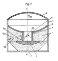
- the units shown in Figs. 1 and 2 have each a hollow explosive charge 1 e. g. trinitrotoluene (TNT) or cyclonite (T4), shown in dotted form, a casing 2 having an open upper end, a-plate 3 of inert material, for example plastic, ceramic or metal, a tubular metal cylinder 4 embedded in the charge 1 and surrounded by a sheath of inert material 8, e. g. resting on a plate 3, a dished metal element 5 lining the hollow in the charge and a cover 6, preferably of synthetic material, closing off the top end of the casing.
- the metal cylinder 4 may be of such a length, as with the embodiment shown in Fig.
- the function of the plate 3 is two-fold : firstly it functions as an attenuator of the resulting shock waves and secondly as a diffraction lens.
- the plate 3 is traversed by a shock wave generated by interaction with a direct detonation wave O dir itself generated at 7 (firing point) and propagated with a velocity Vd, dependent on the explosive material employed.
- the shock wave is attenuated and is capable of causing an explosion under the plate 3 which is of greater diameter than the metal cylinder 4, thereby generating a detonation, low power, wave O br , which is propagated in the explosive material of the hollow charge 1, in the immediate vicinity of the metal cylinder 4, at a velocity Vd 2 , less than Vd l .
- the metal cylinder 4 has the tendency, under the influence of the detonation wave of velocity Vd 2 , of being compressed and of creating a direct high velocity blast along the line of the axis X-X.
- the blast In order to achieve optimal penetration into the object to be destroyed, the blast must have both stable dimensions and stable velocity. To achieve the best possible stability, it is essential that the velocity of propagation of the detonation wave in the metal cylinder 4 be somewhat less than or at most equal to the speed of sound in the material composing cylinder 4. It is for this reason that the metal cylinder 4 is surrounded by a sheath of inert material 8.
- the drop in the velocity Vd 2 in the metal cylinder 4 is naturally dependent on the nature of the material used for the sheath 8 and its thickness.
- This sheath may be cylindrical as shown in Figs. 1 and 2 or it may be frusto-conical in form with its narrow end adjacent to cover 6.
- Vd 2 By reducing the velocity Vd 2 to a value Vd 3 , less than the critical velocity intrinsic to the material used for the metal cylinder 4, suitable conditions are created for the generation of a stable blast, that is to say a blast that does not lengthen or disperse during propagation.
- the length of the blast is practically equal to the height of the metal cylinder 4, while its velocity VB, directed along the axis X-X, is substantially equal to twice Vd 3 , Vd 3 being equal to the velocity of propagation of the explosion wave in the metal cylinder 4.
- the part of the metal cylinder 4 which is flush with the upper face of the dished metal element 5 or which extends above the latter behaves, in the formation of the first projectile, in the same way as the portion immersed in the explosive.
- This part which is subjected to the stresses imposed by the dished element 5 and projected under the impulsive force of the detonating mass, continues to feed the mass of the projectile already in motion.
- the second function of the plate 3 is that of acting as a diffraction lens.
- the direct detonation wave O dir surrounding the inert plate 3, imparts to the diffraction wave Odit an appropriate shape before acting with the dished metal element 5, to constitute a second projectile which travels behind the first projectile formed by the metal cylinder 4 surrounded by the sheath of inert material 8.
- the hybrid explosive unit provided by the present invention is also suited for use in artillery shells, inter alia.
Landscapes
- Engineering & Computer Science (AREA)
- General Engineering & Computer Science (AREA)
- Aiming, Guidance, Guns With A Light Source, Armor, Camouflage, And Targets (AREA)
- Pressure Welding/Diffusion-Bonding (AREA)
- Fixed Capacitors And Capacitor Manufacturing Machines (AREA)
- Drilling And Exploitation, And Mining Machines And Methods (AREA)
Claims (6)
Priority Applications (1)
| Application Number | Priority Date | Filing Date | Title |
|---|---|---|---|
| AT84903886T ATE29583T1 (de) | 1983-10-04 | 1984-10-03 | Hybride munition. |
Applications Claiming Priority (2)
| Application Number | Priority Date | Filing Date | Title |
|---|---|---|---|
| CH5387/83 | 1983-10-04 | ||
| CH5387/83A CH654104A5 (fr) | 1983-10-04 | 1983-10-04 | Ensemble explosif hybride. |
Publications (2)
| Publication Number | Publication Date |
|---|---|
| EP0159353A1 EP0159353A1 (de) | 1985-10-30 |
| EP0159353B1 true EP0159353B1 (de) | 1987-09-09 |
Family
ID=4292724
Family Applications (1)
| Application Number | Title | Priority Date | Filing Date |
|---|---|---|---|
| EP84903886A Expired EP0159353B1 (de) | 1983-10-04 | 1984-10-03 | Hybride munition |
Country Status (15)
| Country | Link |
|---|---|
| US (1) | US4665826A (de) |
| EP (1) | EP0159353B1 (de) |
| JP (1) | JPS61501791A (de) |
| AU (1) | AU571282B2 (de) |
| BR (1) | BR8407100A (de) |
| CH (1) | CH654104A5 (de) |
| DE (1) | DE3466063D1 (de) |
| DK (1) | DK151839C (de) |
| ES (1) | ES293415Y (de) |
| GR (1) | GR80540B (de) |
| IN (1) | IN161164B (de) |
| IT (1) | IT1181577B (de) |
| PT (1) | PT79312B (de) |
| WO (1) | WO1985001572A1 (de) |
| ZA (1) | ZA847759B (de) |
Families Citing this family (25)
| Publication number | Priority date | Publication date | Assignee | Title |
|---|---|---|---|---|
| DE3426847C1 (de) * | 1984-07-21 | 1992-04-09 | Diehl Gmbh & Co | Projektilbildende Sprengladungseinlage |
| DE3628622C1 (de) * | 1986-08-22 | 1996-08-08 | Fraunhofer Ges Forschung | Vorrichtung zur Erzeugung sprenggeformter Projektile |
| US4729318A (en) * | 1987-03-12 | 1988-03-08 | The United States Of America As Represented By The United States Department Of Energy | Explosive plane-wave lens |
| GB2272046B (en) * | 1989-01-06 | 1994-10-05 | Marconi Co Ltd | Mine |
| US5038683A (en) * | 1989-08-31 | 1991-08-13 | The United States Of America As Represented By The Secretary Of The Army | High explosive assembly for projecting high velocity long rods |
| FR2667140B1 (fr) * | 1990-09-26 | 1993-07-16 | Commissariat Energie Atomique | Dispositif pyrotechnique de production de jets de matiere a tres hautes vitesses et installation a perforations multiples. |
| US5251561A (en) * | 1992-06-11 | 1993-10-12 | The United States Of America As Represented By The United States Department Of Energy | Open apex shaped charge-type explosive device having special disc means with slide surface thereon to influence movement of open apex shaped charge liner during collapse of same during detonation |
| AU652710B3 (en) * | 1992-12-24 | 1994-09-01 | Dyno Wesfarmers Limited | Shaped charges |
| GB9916670D0 (en) * | 1999-07-16 | 2000-03-08 | British Nuclear Fuels Plc | Explosive charges |
| DE10332257A1 (de) * | 2003-07-16 | 2005-02-03 | Rheinmetall W & M Gmbh | Gefechtskopf |
| US6925924B2 (en) * | 2003-10-14 | 2005-08-09 | Molycorp Inc. | Method and apparatus to improve perforating effectiveness using a unique multiple point initiated shaped charge perforator |
| RU2256146C1 (ru) * | 2004-02-06 | 2005-07-10 | Федеральное государственное унитарное предприятие "Научно-исследовательский инженерный институт" (ФГУП "НИИИ") | Мина противотанковая кумулятивно-фугасная |
| DE102005044320B4 (de) * | 2005-09-16 | 2010-11-11 | Fraunhofer-Gesellschaft zur Förderung der angewandten Forschung e.V. | Ladung mit einer im wesentlichen zylindrischen Sprengstoffanordnung |
| FR2902869B1 (fr) * | 2006-06-22 | 2010-09-10 | Giat Ind Sa | Tete militaire engendrant un noyau tubulaire. |
| US7921775B1 (en) * | 2006-08-29 | 2011-04-12 | Raytheon Company | Warhead booster explosive lens |
| RU2413925C1 (ru) * | 2009-07-06 | 2011-03-10 | Российская Федерация, от имени которой выступает Министерство обороны Российской Федерации | Противотанковая кумулятивная мина ручной установки |
| US9395128B2 (en) * | 2012-08-29 | 2016-07-19 | Corvid Technologies, Inc. | Projectile launching devices and methods and apparatus using same |
| US9175940B1 (en) | 2013-02-15 | 2015-11-03 | Innovation Defense, LLC | Revolved arc profile axisymmetric explosively formed projectile shaped charge |
| US10048047B2 (en) * | 2014-08-06 | 2018-08-14 | Alba Manufacturing Corp. | Explosive booster |
| US9612095B2 (en) * | 2014-12-12 | 2017-04-04 | Schlumberger Technology Corporation | Composite shaped charges |
| US20160216085A1 (en) * | 2015-01-27 | 2016-07-28 | The United State Of America As Represented By The Secretary Of The Navy | Structure for Shaping and Applying a Propagating Shock Wave to an Area of an Explosive Load to Increase an Energetic Shock Impact Effect on a Target |
| US9360222B1 (en) | 2015-05-28 | 2016-06-07 | Innovative Defense, Llc | Axilinear shaped charge |
| US10364387B2 (en) | 2016-07-29 | 2019-07-30 | Innovative Defense, Llc | Subterranean formation shock fracturing charge delivery system |
| US10690459B1 (en) * | 2018-03-23 | 2020-06-23 | The United States Of America As Represented By The Secretary Of The Navy | Detonation-wave-shaping fuze booster |
| KR102009961B1 (ko) * | 2018-04-24 | 2019-08-12 | 임대규 | 특수 폭약을 활용한 무천공 발파공법 |
Family Cites Families (10)
| Publication number | Priority date | Publication date | Assignee | Title |
|---|---|---|---|---|
| US2809585A (en) * | 1949-11-16 | 1957-10-15 | Sidney A Moses | Projectile for shaped charges |
| GB941430A (en) * | 1952-02-20 | 1963-11-13 | John Noel Stebbing Junior | Improvements in rockets |
| US4213391A (en) * | 1953-05-07 | 1980-07-22 | The United States Of America As Represented By The Secretary Of The Army | Anti-tank mine with peripheral charge initiation |
| DE1571260C3 (de) * | 1966-03-16 | 1973-09-20 | Fa. Diehl, 8500 Nuernberg | Vorrichtung zum gleichmaßigen, zentrischen Zünden einer rotationssymme tnschen Hohlladung |
| CH475543A (de) * | 1966-04-20 | 1969-07-15 | Diehl Fa | Hohlladung für Landminen |
| GB1237392A (en) * | 1967-12-15 | 1971-06-30 | Messerschmitt Boelkow Blohm | Improvements in explosive charges |
| DE1703593B1 (de) * | 1968-06-14 | 1971-09-30 | Messerschmitt Boelkow Blohm | Hohlladung,insbesondere fuer einen Flugkoerper ausgebildeter rotationssymmetrischer Hohlladungssprengkoerper mit Detonationswellenlenkung |
| DE2813179C3 (de) * | 1978-03-25 | 1980-09-18 | Dynamit Nobel Ag, 5210 Troisdorf | Verfahren zum Herstellen von gepreßten Sprengladungen |
| FR2445945A1 (fr) * | 1979-01-05 | 1980-08-01 | Luchaire Sa | Perfectionnements apportes aux charges creuses en tandem |
| DE3019948C2 (de) * | 1980-05-24 | 1983-01-05 | Messerschmitt-Bölkow-Blohm GmbH, 8000 München | Vorrichtung zum Initiieren einer Sprengladung |
-
1983
- 1983-10-04 CH CH5387/83A patent/CH654104A5/fr not_active IP Right Cessation
-
1984
- 1984-10-03 PT PT79312A patent/PT79312B/pt unknown
- 1984-10-03 JP JP59503904A patent/JPS61501791A/ja active Pending
- 1984-10-03 EP EP84903886A patent/EP0159353B1/de not_active Expired
- 1984-10-03 AU AU35519/84A patent/AU571282B2/en not_active Ceased
- 1984-10-03 US US06/747,049 patent/US4665826A/en not_active Expired - Fee Related
- 1984-10-03 BR BR8407100A patent/BR8407100A/pt unknown
- 1984-10-03 WO PCT/EP1984/000313 patent/WO1985001572A1/en not_active Ceased
- 1984-10-03 DE DE8484903886T patent/DE3466063D1/de not_active Expired
- 1984-10-03 GR GR80540A patent/GR80540B/el unknown
- 1984-10-03 ZA ZA847759A patent/ZA847759B/xx unknown
- 1984-10-04 ES ES1984293415U patent/ES293415Y/es not_active Expired
- 1984-10-04 IT IT85643/84A patent/IT1181577B/it active
- 1984-10-08 IN IN781/DEL/84A patent/IN161164B/en unknown
-
1985
- 1985-06-03 DK DK247185A patent/DK151839C/da not_active IP Right Cessation
Also Published As
| Publication number | Publication date |
|---|---|
| DK151839B (da) | 1988-01-04 |
| ES293415Y (es) | 1987-12-01 |
| WO1985001572A1 (en) | 1985-04-11 |
| ES293415U (es) | 1987-04-16 |
| DK151839C (da) | 1988-06-27 |
| EP0159353A1 (de) | 1985-10-30 |
| PT79312B (fr) | 1986-08-19 |
| GR80540B (en) | 1985-01-28 |
| DK247185D0 (da) | 1985-06-03 |
| DK247185A (da) | 1985-06-03 |
| IN161164B (de) | 1987-10-10 |
| IT8485643A0 (it) | 1984-10-04 |
| AU3551984A (en) | 1985-04-23 |
| JPS61501791A (ja) | 1986-08-21 |
| ZA847759B (en) | 1985-05-29 |
| IT1181577B (it) | 1987-09-30 |
| BR8407100A (pt) | 1985-08-27 |
| US4665826A (en) | 1987-05-19 |
| AU571282B2 (en) | 1988-04-14 |
| CH654104A5 (fr) | 1986-01-31 |
| PT79312A (fr) | 1984-11-01 |
| DE3466063D1 (en) | 1987-10-15 |
Similar Documents
| Publication | Publication Date | Title |
|---|---|---|
| AU571282B2 (en) | Hybrid explosive unit | |
| US4922826A (en) | Active component of submunition, as well as flechette warhead and flechettes therefor | |
| US5780766A (en) | Guided missile deployable as mortar projectile | |
| US5542354A (en) | Segmenting warhead projectile | |
| US3948181A (en) | Shaped charge | |
| US4102271A (en) | Armor-piercing tandem shell or projectile | |
| US6494139B1 (en) | Hole boring charge assembly | |
| US4967666A (en) | Warhead against fortified or armored targets, particularly for damaging runways, roadway pavings, bunker walls or the like | |
| US4854240A (en) | Two-stage shaped charge projectile | |
| US4111126A (en) | Warhead for use against armored targets | |
| US4768440A (en) | Warhead for missiles | |
| US5223666A (en) | Apparatus for clearing mines | |
| GB2384291A (en) | General purpose bomb | |
| US5394804A (en) | Explosive device with a hollow charge, designed for penetrating armor protected by active primary armor | |
| US3495532A (en) | Antitank land mine | |
| US4488487A (en) | Stepped body penetration bomb | |
| JP2989016B2 (ja) | 徹甲弾頭 | |
| EP0298494B1 (de) | Submunitions-Wirkteil, sowie Flechettes-Gefechtskopf und Flechettes dafür | |
| US3176613A (en) | Shaped explosive charge | |
| US6167811B1 (en) | Reverse initiation device | |
| US6053109A (en) | Triggering arrangement for the priming of an anti-shelter projectile | |
| US4510870A (en) | Charge liner construction and method | |
| CA2324860C (en) | Wall breaching warhead | |
| GB2113362A (en) | Hollow charges | |
| GB2179125A (en) | Warhead |
Legal Events
| Date | Code | Title | Description |
|---|---|---|---|
| PUAI | Public reference made under article 153(3) epc to a published international application that has entered the european phase |
Free format text: ORIGINAL CODE: 0009012 |
|
| 17P | Request for examination filed |
Effective date: 19850529 |
|
| AK | Designated contracting states |
Designated state(s): AT BE DE FR GB SE |
|
| TCAT | At: translation of patent claims filed | ||
| 17Q | First examination report despatched |
Effective date: 19860620 |
|
| DET | De: translation of patent claims | ||
| GRAA | (expected) grant |
Free format text: ORIGINAL CODE: 0009210 |
|
| AK | Designated contracting states |
Kind code of ref document: B1 Designated state(s): AT BE DE FR GB SE |
|
| REF | Corresponds to: |
Ref document number: 29583 Country of ref document: AT Date of ref document: 19870915 Kind code of ref document: T |
|
| ET | Fr: translation filed | ||
| REF | Corresponds to: |
Ref document number: 3466063 Country of ref document: DE Date of ref document: 19871015 |
|
| PLBE | No opposition filed within time limit |
Free format text: ORIGINAL CODE: 0009261 |
|
| STAA | Information on the status of an ep patent application or granted ep patent |
Free format text: STATUS: NO OPPOSITION FILED WITHIN TIME LIMIT |
|
| 26N | No opposition filed | ||
| PG25 | Lapsed in a contracting state [announced via postgrant information from national office to epo] |
Ref country code: GB Effective date: 19891003 Ref country code: AT Effective date: 19891003 |
|
| PG25 | Lapsed in a contracting state [announced via postgrant information from national office to epo] |
Ref country code: SE Effective date: 19891004 |
|
| PG25 | Lapsed in a contracting state [announced via postgrant information from national office to epo] |
Ref country code: BE Effective date: 19891031 |
|
| BERE | Be: lapsed |
Owner name: BRIND ANSTALT FUR INDUSTRIE PATENTE Effective date: 19891031 |
|
| GBPC | Gb: european patent ceased through non-payment of renewal fee | ||
| PG25 | Lapsed in a contracting state [announced via postgrant information from national office to epo] |
Ref country code: FR Effective date: 19900629 |
|
| PG25 | Lapsed in a contracting state [announced via postgrant information from national office to epo] |
Ref country code: DE Effective date: 19900703 |
|
| REG | Reference to a national code |
Ref country code: FR Ref legal event code: ST |
|
| EUG | Se: european patent has lapsed |
Ref document number: 84903886.4 Effective date: 19900706 |